
|
|
Forum Index : Microcontroller and PC projects : Circuit diagram
| Author | Message | ||||
lew247 Guru Joined: 23/12/2015 Location: United KingdomPosts: 1709 |
Just to keep this thread updated: I've finished the design for the indoor unit. I won't post the the circuit here yet, I'll wait till I have the boards in my hand and get them made up so I can check they do work properly. When I've finished and happy both boards work properly as designed, I'll post the complete project, circuits, board design, gerbers and so on. Hopefully someone will want to make one as well and "Hopefully" some people will want to try and write better software than I am capable of, or at least tidy it up, or add new features. I've made 2 indoor unit 1 to fit on the back of a 7" SDD1963 touchscreen LCD display that should fit perfectly (hopefully) The 2nd is on a smaller board 75 X 75 that will still plug into the header used on the SDD1963 touchscreen display but is smaller and will fit the smaller versions of the display. Although you can't tell from the picture, the larger board will mount on the back of the 7" display. I've used a mini usb socket on the smaller one, but on the larger it's a header as I have several micro usb sockets that are on a small board with a header and they will just plug in. ALL the connections on the boards are standard 0.1" (2.554mm) pitch so any kind of header, screw terminal, molex or whatever you want with that pitch can be used Ignore the headers in the picture - only for show - anything can be used. On the indoor unit, I have an LDR to dim the display at night, DS3231 RTC W25Q64 Serial Flash ESP8266 WiFi module upload weather to Wunderground or other/download bmp of the cloud conditions? lots of options with this module HC-12 433Mhz module Console and ICSP headers USB input and 5V input Buzzer module (touchscreen beep?) DS18B20 Temp module and of course a Pic32MX470 64 pin Micromite (once programmed) I don't think I've forgotten anything but if I have .. I'#ll come back to it after 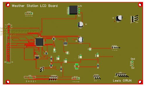
|
||||
| lew247 Guru Joined: 23/12/2015 Location: United KingdomPosts: 1709 |
The outdoor board has arrived from China, and the LCD unit board should arrive Friday I hope. As you can see I'm VERY inexperienced using Diptrace or any circuit making program, this was my first board and I made some obvious errors. 1. The mounting holes are too small (I forgot to specify the hole size DUH!) 2. The tracks should be made wider where it's possible to do so, I did make the power lines thicker than the rest but maybe they should be thicker still, not sure as its only a few mA going through them at any one time and a maximum of 500mA and only for a few seconds at a time so they should be fine anyway. 3. One of the sensors has the silkscreen writing the wrong way round on 2 pins. I guess not too many errors seeing it was my first board, so I'm reasonably happy. The silkscreen error is already fixed in the Gerber files and I'll sort the rest of the problems out later. I've also changed the silkscreen so it shows the value of each component as well. Once the LCD unit board has arrived I can see about getting the components mounted and getting testing the software.  |
||||
bigmik Guru Joined: 20/06/2011 Location: AustraliaPosts: 2981 |
Congratulations Lewis, Looks pretty good. and quick off the mark.. Did you ever check your power control circuit? I think it will work but I havent yet tried it out in the flesh.. Regards, Mick Mick's uMite Stuff can be found >>> HERE (Kindly hosted by Dontronics) <<< |
||||
| lew247 Guru Joined: 23/12/2015 Location: United KingdomPosts: 1709 |
Nope, I've no way of actually testing it until I get the unit put together as my Micromite+ blew it's PSU when I tried using too many modules at once and I don't have any other working Micromite here at the moment. The fault with the silkscreen is annoying, the Si1145 has the +V and Gnd reversed, not a major problem but it's annoying. I've tested every trace with a meter and they all go to where they are meant to so it's looking hopeful. The one thing that surprised me is how SMALL the board is 50 X 50 sounds a reasonable size but it's th same size as the tip of my middle finger to the 2nd knuckle |
||||
| bigmik Guru Joined: 20/06/2011 Location: AustraliaPosts: 2981 |
@Lew, No big deal, just print out onto a sticker with the right size font and stick it over the incorrect overlay.. Maybe even DYMO tape will be ok. Regards, Mick Mick's uMite Stuff can be found >>> HERE (Kindly hosted by Dontronics) <<< |
||||
| lew247 Guru Joined: 23/12/2015 Location: United KingdomPosts: 1709 |
Just to keep this updated - again. The LCD boards arrived from China No silkscreen problems and everything was where it was meant to be but unfortunately there was a problem in the circuit which I never spotted. Also the pinouts for some of the modules were wrong, both on this and the outdoor unit. I've corrected the mistakes in the circuit, I'm going to get the board made up and "wire" the corrections - will look a bit messy but as this will only be for me it's not a problem really And I'll be able to test the complete circuit properly. I've also added a 3rd board which does something else - but I'll leave saying what that is until I get these two working properly first. |
||||
| Phil23 Guru Joined: 27/03/2016 Location: AustraliaPosts: 1667 |
Sounds interesting. Are you considering making it interface with Cumulus? Would certainly be interested in offering a small donation for a project like this. Something of the magnitude of a sensor or two to help development. Maybe to help incorporate Air pressure & solar irradiance. My old Jaycar Weather Station is getting a bit sad. Cheers Edit:- Should have read the entire thread before posting... Misread the start date by a month.... |
||||
| bigmik Guru Joined: 20/06/2011 Location: AustraliaPosts: 2981 |
Hi Lew, I tested the above circuit and can confirm that it works perfectly.. There is also, as Hank stated, no need for the 10k pull-up resistor. I used a MuP to power another MuP that was driving my Mik-Matrix panel with 5 LED matrix panels. With the IO pin set high the second MuP was powered off with the IO pin set low the second MuP powered up.. Using one of those cheap modules that plugs inline on the USB port that measures current shows no detectable difference in current draw with the second MuP connected and off than if it was disconnected.. The LED also illuminates with about 3/4 optimal intensity when on and totally off when off. Considering the simplicity of that circuit I can recommend it to be put in the circuit bank if we have one.. The LED is the secret to this working, I used a standard GREEN one and results may vary with blue or white ones due to the higher forward voltage which may stop the circuit from working effectively.. Regards, Mick PS... There was about 0.22v drop across the transistor.. Of course higher current draw would need an appropriate transistor to be used. Mik Mick's uMite Stuff can be found >>> HERE (Kindly hosted by Dontronics) <<< |
||||
| lew247 Guru Joined: 23/12/2015 Location: United KingdomPosts: 1709 |
Phil23 I'd not heard of that before you posted it, it looks like a really nice software package. I don't know the format that the software is expecting - maybe someone else knows? BUT the indoor unit has a wifi interface so you can communicate with a web page and it has a usb interface so you can connect it to the computer. IF someone knows how the Cumulus works, ie how it gets the data and in what format, it shouldn't be too hard to incorporate I wouldn't think. By the way - it already incorporates Lux and UV Index sensors Thanks Mick, I'm "hoping" to have the boards built up in the next week or two so I'll be able to carry on and get all this working Then it's the hard bit - getting all the software working like I envisage, although hopefully it won't be too hard thanks to all the helpful people on here and especially matherp who has solved the problem I had with the analog clock I wanted on the screen. |
||||
| spjoruss Newbie Joined: 01/02/2014 Location: United StatesPosts: 22 |
I have been reading this whole thread with interest. I have always wanted to build my own weather station but it may never happen. I would be starting at ground level. Both with circuits and programming. I started out with a cheap Fine Offset type of weather station. After it started failing I got one that a fellow in Canada designed made with micro controllers. I have been using Cumulus1 for about 3 years which runs on Windows only. It works with these Fine Offset type of stations and a few others also. The developer of Cumulus has now created a new version CumulusMX which will run on Windows or Linux. The station that the fellow in Canada made was designed especially to work with Cumulus. He emulated a Fine Offset station using protocols that some others had reverse engineered. There is another way to access Cumulus with a Easyweather.dat file but that is a very limited way. When you get this thing operating and I see how it works I might be interested in buying one from you. My preference has always been to keep using CumulusMX though. Here are some links to the above information. CumulusMX Fine Offset Protocol More info on Fine Offset Protocol Easyweather.dat Sperry |
||||
| lew247 Guru Joined: 23/12/2015 Location: United KingdomPosts: 1709 |
Whoever said designing circuits is easy? It's really hard to get it all right, I've discovered it takes several goes to get things right. My last effort although correct and would have worked fine has had to be redone because the pins on the esp8266 module was upside down. It would work find mounted under the pcb but I like to get things right so I've redone it. I keep finding small things wrong, and have modified the outdoor circuit 28 times now. It will go right in the end 
|
||||
| lew247 Guru Joined: 23/12/2015 Location: United KingdomPosts: 1709 |
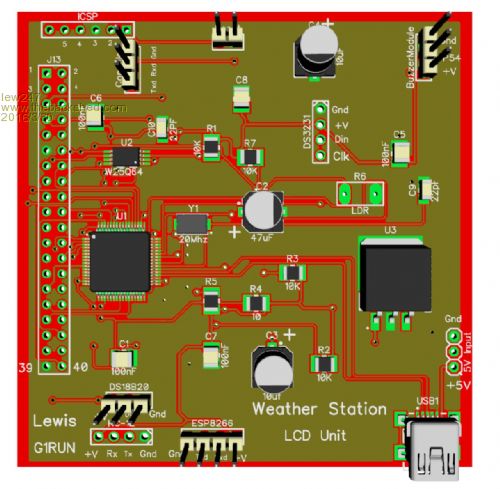
An update on this. I first of all made the boards 50mm X 50mm and they were way too small to solder to properly, let alone have the connectors mounted on properly I then had the outdoor unit made up as a 75mm X 50mm unit and it seemed all good Whitewizzard soldered the smd components for me and tested it to make sure it worked and all was good at first. However when I tried fitting the actual modules to the board I discovered to my horror how stupid I was The modules will not physically fit on the board, so my only option is to either get yet another board made up a bit bigger this time (99mm X 75mm) or Use it "ugly fashion" with the modules not plugged into the board but connected with jumper wires. I wanted this to be neat and tidy with all the modules plugging into one board so it looks like I'm about to get some more boards made up (again - 4th set!!!) The LCD board is great apart from I have the same problem with the RTC module, it will not physically fit where I have the socket mounted. I also made some changes to the board after I had them sent to the PCB house, and Whitewizzard very kindly soldered jumper wires onto the chip to make them work. I am considering getting the LCD module boards redone as well, with the module headers in the correct place this time so they actually plug in and work, and with no wire jumpers. Going to be another 3-4 weeks before this is finished Here's the outdoor unit PLEASE NOTE THE HEADERS ARE NOT SOLDERED that's why they look "crooked" The ESP8266 on the outdoor unit is there so I can program it remotely, if better code comes along after I've mounted it outside I can update it remotely, It's connected to the console header 
Here's how the new one "should look" (simulated pic) and Ive also changed the header sizing on the top row of headers to 3.5mm spacing instead of 2.54 and planning on using screw terminals and the same for the power connector.  |
||||
| The Back Shed's forum code is written, and hosted, in Australia. | © JAQ Software 2026 |
