
|
|
Forum Index : Microcontroller and PC projects : Stepper Project
| Author | Message | ||||
Bryan1 Guru Joined: 22/02/2006 Location: AustraliaPosts: 2136 |
Peter I am trying to get a good understanding just how this stepper system does work now what I'm putting here could it be added to the stepper PDF so a new user to G_code can understand what each G_code does. This is taken off the Hass website I linked before and I hope they don't mind me putting it on here. So here goes G0 G00 Rapid Motion Positioning (Group 01) *X - Optional X-Axis motion command *Y - Optional Y-Axis motion command *Z - Optional Z-Axis motion command *A - Optional A-Axis motion command *B - Optional B-Axis motion command *C - Optional C-axis motion command * E - Optional code to specify the rapid rate of the block as a percent. *indicates optionalG00 is used to move the machine axes at the maximum speed. It is primarily used to quickly position the machine to a given point before each feed (cutting) command. This G code is modal, so a block with G00 causes all following blocks to be rapid motion until another Group 01 code is specified.A rapid move also cancels an active canned cycle, just like G80 does. NOTE: Generally, rapid motion will not be in a single straight line. Each axis specified moves at its maximum speed, but all axes will not necessarily complete their motions at the same time. The machine waits until all motions are complete before starting the next command. G1 G01 Linear Interpolation Motion (Group 01) F - Feedrate * X - X-Axis motion command * Y - Y-Axis motion command * Z - Z-Axis motion command * A - A-Axis motion command * B - B-Axis motion command * C - C-axis motion command * ,R - Radius of the arc * ,C - Chamfer distance *indicates optionalG01 moves the axes at a commanded feed rate. It is primarily used to cut the workpiece. A G01 feed can be a single axis move or a combination of the axes. The rate of axes movement is controlled by feedrate ( F) value. This F value can be in units (inch or metric) per minute ( G94) or per spindle revolution ( G95), or time to complete the motion ( G93). The feedrate value ( F) can be on the current program line, or a previous line. The control will always use the most recent F value until another F value is commanded. If in G93, an F value is used on each line. Refer also to G93.G01 is a modal command, which means that it will stay in effect until canceled by a rapid command such as G00 or a circular motion command like G02 or G03.Once a G01 is started all programmed axes move and reach the destination at the same time. If an axis is not capable of the programmed feedrate the control will not proceed with the G01 command and an alarm (max feedrate exceeded) will be generated.Corner Rounding and Chamfering ExampleCorner Rounding and Chamfering. G02 G02 CW / G03 CCW Circular Interpolation Motion (Group 01) F - Feedrate *I - Distance along X Axis to center of circle *J - Distance along Y Axis to center of circle *K - Distance along Z Axis to center of circle *R - Radius of circle *X - X-Axis motion command *Y - Y-Axis motion command *Z - Z-Axis motion command *A - A-Axis motion command *indicates optional NOTE: I,J and K is the preferred method to program a radius. R is suitable for general radii. These G codes are used to specify circular motion. Two axes are necessary to complete circular motion and the correct plane, G17-G19, must be used. There are two methods of commanding a G02 or G03, the first is using the I, J, K addresses and the second is using the R address.Using I, J, K addressesI, J and K address are used to locate the arc center in relation to the start point. In other words, the I, J, K addresses are the distances from the starting point to the center of the circle. Only the I, J, or K specific to the selected plane are allowed (G17 uses IJ, G18 uses IK and G19 uses JK). The X, Y, and Z commands specify the end point of the arc. If the X, Y, and Z location for the selected plane is not specified, the endpoint of the arc is the same as the starting point for that axis.To cut a full circle the I, J, K addresses must be used; using an R address will not work. To cut a full circle, do not specify an ending point (X, Y, and Z ); program I, J, or K to define the center of the circle. For example: G02 I3.0 J4.0 (Assumes G17; XY plane) ; Using the R addressThe R-value defines the distance from the starting point to the center of the circle. Use a positive R-value for radii of 180 or less, and a negative R-value for radii more than 180. G03 G02 CW / G03 CCW Circular Interpolation Motion (Group 01) F - Feedrate *I - Distance along X Axis to center of circle *J - Distance along Y Axis to center of circle *K - Distance along Z Axis to center of circle *R - Radius of circle *X - X-Axis motion command *Y - Y-Axis motion command *Z - Z-Axis motion command *A - A-Axis motion command *indicates optional NOTE: I,J and K is the preferred method to program a radius. R is suitable for general radii. These G codes are used to specify circular motion. Two axes are necessary to complete circular motion and the correct plane, G17-G19, must be used. There are two methods of commanding a G02 or G03, the first is using the I, J, K addresses and the second is using the R address.Using I, J, K addressesI, J and K address are used to locate the arc center in relation to the start point. In other words, the I, J, K addresses are the distances from the starting point to the center of the circle. Only the I, J, or K specific to the selected plane are allowed (G17 uses IJ, G18 uses IK and G19 uses JK). The X, Y, and Z commands specify the end point of the arc. If the X, Y, and Z location for the selected plane is not specified, the endpoint of the arc is the same as the starting point for that axis.To cut a full circle the I, J, K addresses must be used; using an R address will not work. To cut a full circle, do not specify an ending point (X, Y, and Z ); program I, J, or K to define the center of the circle. For example: G02 I3.0 J4.0 (Assumes G17; XY plane) ; Using the R addressThe R-value defines the distance from the starting point to the center of the circle. Use a positive R-value for radii of 180 or less, and a negative R-value for radii more than 180. G04 G04 Dwell (Group 00) P - The dwell time in seconds or milliseconds NOTE: The P values are modal. This means if you are in the middle of a canned cycle and a G04 Pnn or an M97 Pnn is used the P value will be used for the dwell / subprogram as well as the canned cycle. G04 specifies a delay or dwell in the program. The block with G04 delay for the time specified by the P address code. For example: G04 P10.0. ; Delays the program for 10 seconds. G28 G28 Return to Machine Zero Point (Group 00) The G28 code returns all axes (X, Y, Z, A and B) simultaneously to the machine zero position when no axis is specified on the G28 line.Alternatively, when one or more axes locations are specified on the G28 line, G28 will move to the specified locations and then to machine zero. This is called the G29 reference point; it is saved automatically for optional use in G29.Setting 108 affects the way that rotary axes return when you command a G28. Refer to Setting 108 - Quick Rotary G28 for more information. % G28 G90 X0 Y0 Z0 (moves to X0 Y0 Z0) ; G28 G90 X1. Y1. Z1. (moves to X1. Y1. Z1.) ; G28 G91 X0 Y0 Z0 (moves directly to machine zero) ; G28 G91 X-1. Y-1. Z-1 (moves incrementally -1.) ; % G90 G90 Absolute / G91 Incremental Position Commands (Group 03) These G codes change the way the axis commands are interpreted. Axes commands following a G90 will move the axes to the machine coordinate. Axes commands following a G91 will move the axis that distance from the current point. G91 is not compatible with G143 (5-Axis Tool Length Compensation).The Basic Programming section of this manual, beginning with Absolute vs. Incremental Positioning (G90, G91) G91 G90 Absolute / G91 Incremental Position Commands (Group 03) These G codes change the way the axis commands are interpreted. Axes commands following a G90 will move the axes to the machine coordinate. Axes commands following a G91 will move the axis that distance from the current point. G91 is not compatible with G143 (5-Axis Tool Length Compensation).The Basic Programming section of this manual, beginning with Absolute vs. Incremental Positioning (G90, G91) G92 G92 Set Work Coordinate Systems Shift Value (Group 00) This G-code does not move any of the axes; it only changes the values stored as user work offsets. G92 works differently depending on Setting 33, which selects a FANUC or HAAS coordinate system.FANUC or HAASIf Setting 33 is set to FANUC or HAAS, a G92 command shifts all work coordinate systems (G54-G59, G110-G129) so that the commanded position becomes the current position in the active work system. G92 is non-modal.A G92 command cancels any G52 in effect for the commanded axes. Example: G92X1.4 cancels the G52 for the X-Axis. The other axes are not affected.The G92 shift value is displayed at the bottom of the Work Offsets page and may be cleared there if necessary. It is also cleared automatically after power-up, and any time [ZERO RETURN] and [ALL] or [ZERO RETURN] and [SINGLE] are used.G92 Clear Shift Value From Within a ProgramG92 shifts may be canceled by programming another G92 shift to change the current work offset back to the original value. % O60921 (G92 SHIFT WORK OFFSETS) ; (G54 X0 Y0 Z0 is at the center of mill travel) ; G00 G90 G54 X0 Y0 (Rapid to G54 origin) ; G92 X2. Y2. (Shifts current G54) ; G00 G90 G54 X0 Y0 (Rapid to G54 origin) ; G92 X-2. Y-2. (Shifts current G54 back to original) ; G00 G90 G54 X0 Y0 (Rapid to G54 origin) ; M30 (End program) ; Now I have to add here when using G90-G91 it does reference back to G54 G54 G54-G59 Select Work Coordinate System #1 - #6 (Group 12) These codes select one of more than six user coordinate systems. All future references to axes positions will be interpreted using the new (G54G59) coordinate system. See also G154 for additional work offsets. So with my stepper project once I set up each axis the 3 display box's of X,Y,Z is going to show the machine position so we need atleast G54 put in the stepper code so when the surface grinder is setup an absolute position is going to be there and this where the G54 command would come into it's own. So stepper gc, G54, $x,$y,$z Now for the M Commands M03 Spindle Fwd / M04 Spindle Rev / M05 Spindle Stop M03 turns the spindle on in the forward direction.M04 turns the spindle on in the reverse direction.M05 stops the spindle, and waits for it to stop.Spindle speed is controlled with an S address code; for example, S5000 commands a spindle speed of 5000 RPM. Now alot of this can be condensed and from this whole post the G54 command would be nice. Regards Bryan Edited 2026-05-08 20:17 by Bryan1 |
||||
| Bryan1 Guru Joined: 22/02/2006 Location: AustraliaPosts: 2136 |
So basically with my code for this project is setup jogging each axis this when done can be the end of V0.001 as that task is completed.  Now with the surface grinder once the G54 position is programmed in that could go in the library as the machine can set in that position with a few tweaks using the jogging pages for each axis. Now for the Z axis an option where a step value can be put in as an option and lets say each step is 0.001" thats enough for a cut on the grinding wheel as too heavy a cut could throw the job off the magnetic table. I'm sure Lyle will agree as setting up surface grinder does need all the safe guards where a manual E_Stop close by can be hit where the Z axis moves up out of the way so I am wondering can this be done in software. I am an old school heavy machinist and back in '84 when I finished my apprenticeship I was put in No.1 Machine shop at Port Kembla BHP and got asked to use this new 5 million dollar CNC horizontal mill where I learnt G_Code in a very short time as for each operation I had to code it in. Did it for 3 months and my mates got me into doing shutdowns so working above my pay grade just to use a machine became a short job. Regards Bryan Edited 2026-05-08 20:50 by Bryan1 |
||||
| mozzie Guru Joined: 15/06/2020 Location: AustraliaPosts: 400 |
G'day Bryan, Looks like you are making great progress  That PCB is coming along nicely, only thing I would suggest to add is opto-couplers on the limit switch inputs. I have spent many hours chasing obscure faults caused by voltage being induced into the limit wiring from the stepper drivers. This is my suggested circuit: 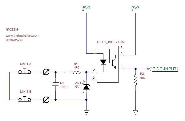 This could of course be on a separate PCB. Also the 22K resistor in the ENABLE circuit should go to 3V3 rather than ground, this DISABLES the drivers when the Stepper system shuts down and releases the pins. I did ask Peter about the possibility of G54/G55 work offset but as he rightly replied, the inbuilt stepper system is not a full motion controller so some things we are going to have to do in our software. We do have G92 to use. The surface grinder E-Stop system is going to be a bit of a problem. As you say, the Z-Axis really needs to raise and clear the job as the spindle winds down. A solution may be to wire the X + Y Axis enables through the E-Stop and when the E-Stop is hit the stepper system is shut down, then we pulse the Z-Axis step pin in our software to clear the table and then STOP. Most times by the time I hit the E-Stop the wheel has a big chunk missing and the job is embedded in the wall some distance away  Also thinking about manual jogging of the axis' might be easier outside the Stepper system, just pulse the step and direction GPIO from a timer / settick / loop and then re-enable the stepper system to run the G-Code. Just a few ideas. Regards, Lyle. Edited 2026-05-09 01:58 by mozzie |
||||
| Bryan1 Guru Joined: 22/02/2006 Location: AustraliaPosts: 2136 |
Yesterday I was thinking about the 2040 zero and what it could do apart from just monitoring the battery voltage well there is enough in/outs on the zero to do all 7 LED's so the 6 axis limits and the E_Stop. Also I could put a 3V3 power module on the pcb to provide the 3V3 for the circuit. I do have one zero setup on one of Mixtels boards so it is breadboard friendly so all the testing can be done. Now the idea of toggling each axis out of the stepper system does seem like a good idea as one would input a distance in the number box which could be used as the distance $ then just pressing the toggle button can keep repeating the move. Also yesterday made a start on the Z axis stepper so with a bit of luck I have have that going then the big job of machining the old X axis handle to fit the 56 tooth sprocket and the support for the X axis stepper motor. Now as the program upload time is now 3 minutes and with every line of code that time is going to stretch and with the amount of errors that will come up it's going to be another very long day.  For the limits switch's I did look in the Altronics catalogue where for $7 each a leg with a roller on would suit nicely, still looking for cheaper one's so any suggestions will be appreciated. Regards Bryan Edited 2026-05-09 10:55 by Bryan1 |
||||
disco4now Guru Joined: 18/12/2014 Location: AustraliaPosts: 1130 |
Bryan, That seems like a long time. How are you loading, how many lines in the program. Are you using AUTOSAVE N Gerry F4 H7FotSF4xGT |
||||
| Bryan1 Guru Joined: 22/02/2006 Location: AustraliaPosts: 2136 |
Gerry I just use MMEdit and MCCC to upload and at first I had a 5 metre usb cable connected so took that out and used a shorter USB cable but the time didn't shorten. Off memory I'm upto 124 lines of code which will be close to 200 lines by the time I get the toggle buttons working. |
||||
| phil99 Guru Joined: 11/02/2018 Location: AustraliaPosts: 3316 |
Just did a test load of a 195 line program to a Pico with latest firmware, using MMEdit via MMCC. Time taken was about 20 seconds, 3 min seems very odd. |
||||
| Bryan1 Guru Joined: 22/02/2006 Location: AustraliaPosts: 2136 |
Ok the rain stopped so up at my shed and just reloaded the code 116 lines Uploading using: 'target port\COM9:921600 s\picomite Upload started NEW > autosav Upload completed 1 Saved 4111 bytes > Time taken: 174950mS Also had the stop watch going on my phone 3.03 minutes so sure whats going on with these long load times. |
||||
| Bryan1 Guru Joined: 22/02/2006 Location: AustraliaPosts: 2136 |
OK found I had an older version of MMEdit so went to Geoff's site and got the latest version. Uploading using: 'target port\COM9:921600 s\picomite Upload started NEW > AUTOSAVE Progress: 100/115 Upload completed 1 Saved 4111 bytes > Time taken: 3051mS So that was my issue now the stop watch got to 7 seconds for the lcd to light up |
||||
| disco4now Guru Joined: 18/12/2014 Location: AustraliaPosts: 1130 |
Bryan, Did you update MMCC as well. The latest versions should try to use AUTOSAVE N which is quicker as no echo back. Maybe your higher speed of 921600 is counter productive, maybe worth seeing if 115200 is better? Connected to COM6 at 115200 C:\Users\gerry\Documents\MMBasic\SPTests\X\tst_library.bas Uploading using: 'target port\COM6:115200 s\picomite Upload started NEW > AUTOSAVE N Progress: 100/108 Upload completed 1 Saved 3188 bytes > Time taken: 1362mS F4 H7FotSF4xGT |
||||
| Bryan1 Guru Joined: 22/02/2006 Location: AustraliaPosts: 2136 |
Hi Gerry I only unzipped MMEdit and just reset the baud rate back to 115200 Uploading using: 'target port\COM9:115200 s\picomite Upload started NEW > AUTOSAVE Progress: 100/115 Upload completed 1 Saved 4111 bytes > Time taken: 3071mS Now at the start of the upload it did say autosave N and that is plenty quick enough for me I'm now on getting that Z axis stepper mount finished and I will show a picture once it's mounted. Regards Bryan |
||||
| Bryan1 Guru Joined: 22/02/2006 Location: AustraliaPosts: 2136 |
Well finally got the Z axis stepper mount all finished 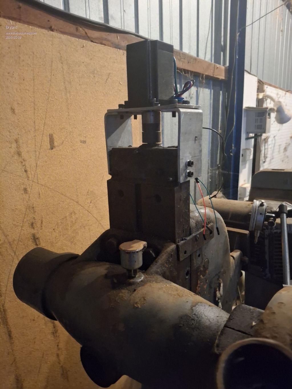 So now gotta put my thinking caps on as the X axis which is going to be a bit of work as I'm using chain sprockets a guard will have to be made. Regards Bryan |
||||
| Bryan1 Guru Joined: 22/02/2006 Location: AustraliaPosts: 2136 |
Well another busy day machining and finally got the large sprocket mounted on the X axis 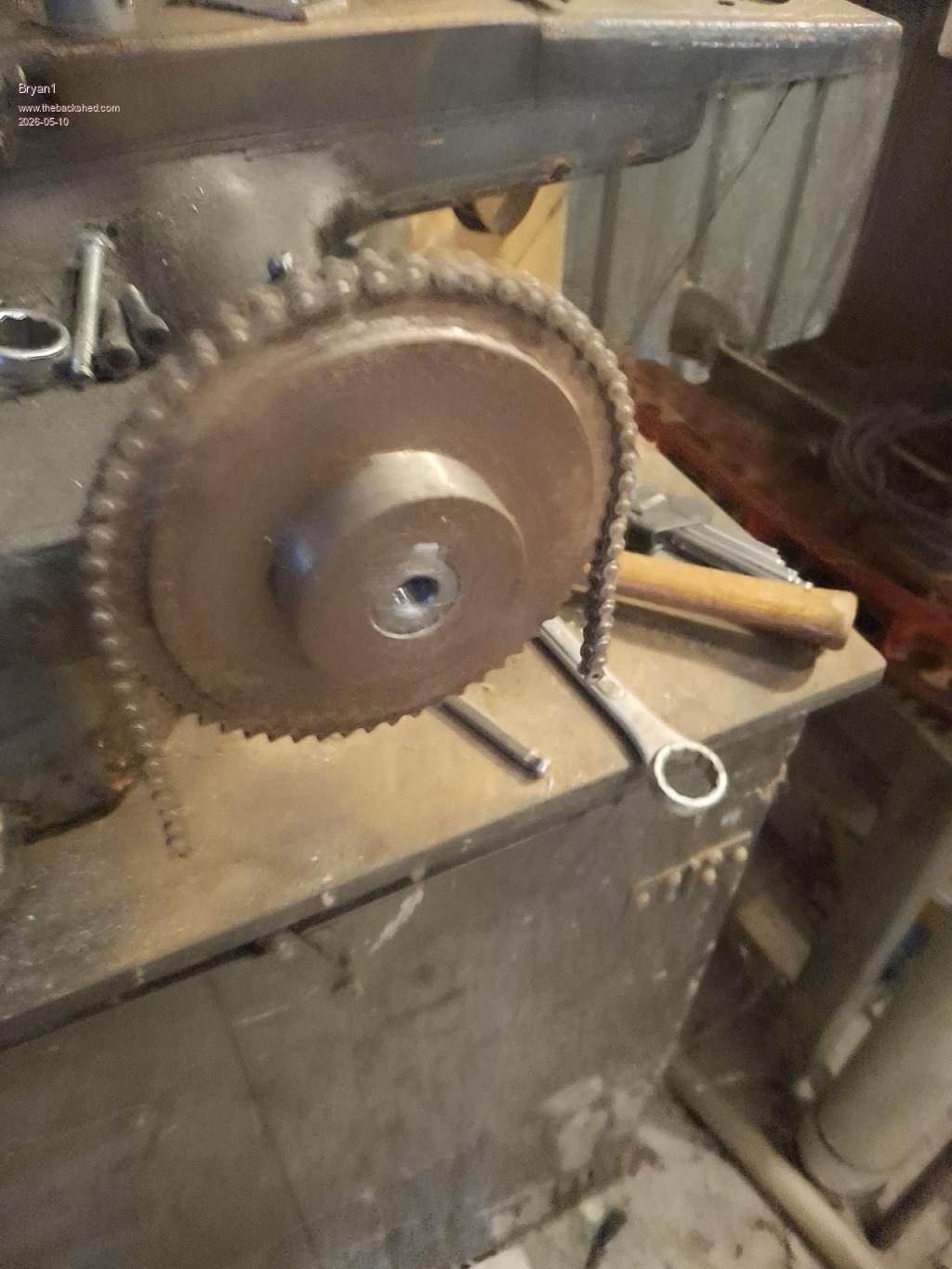 Still got to machine a thick washer so the sprocket can't move forward but I doubt it will as everything is tap in fit Now trying to find that 1/4" chain I bought 20 years ago is still in it's hiding place so may just have to buy a new pack of chain.The small sprocket will be mounted with the small sprocket as there won't be any end float to worry about and chain drives are pretty forgiven on motor bearings etc. Also got to get some colour coded spools of wire for hooking up the steppers which I'll get when I get the chain. Edit: Wouldn't one know it went into town to get something for dinner walked in the shed and that long length of 1/4" chain was straight in my eyesight Now found a scrap section on some 5mm plate to make the backing plate so that's tomorrows job.Edited 2026-05-10 16:49 by Bryan1 |
||||
| PhenixRising Guru Joined: 07/11/2023 Location: United KingdomPosts: 1988 |
Hey Bryan. Not at my PC so I haven't had a good look at the SL6 file but the last image that you posted has thermal pad issues. The 22K resistor on the left has thermal pads on both ends. The thermal pads on the Pico socket need to be 3 o'clock and 9 o'clock. The 6 and 12 need to go away. I'll have a better scan at it when I get to my desk. |
||||
| Bryan1 Guru Joined: 22/02/2006 Location: AustraliaPosts: 2136 |
Phenix I did have a look at that SL6 file and noticed the dual thermal pads so fixed them but the lower central BC337 pads just won't connect to to the earth no matter what I tried so today I will get rid of the ground on plane on C1 and do do some tracks so it all connects. One thing I did find when trying to do a thermal pad on C2 SL6 did the same to all of the pads which was quite frustrating. Not sure what you mean about this 3 o'clock 9 o'clock 6 and 12 o'clock actually means mate. |
||||
| phil99 Guru Joined: 11/02/2018 Location: AustraliaPosts: 3316 |
Looking at the last image on the previous page the ground pads of the Pico appear to have bridges to the pads above (12 o'clock) and below (6 o'clock), which you don't want. The bridges to the left (9 o'clock) and right (3 o'clock) go to the ground plane as they should. Same issue on the ground pads on both the connectors on the right side of the board. And as Phenix pointed out, the resistor above the Pico has bridges to the ground plane at the left end that shouldn't be there. Edited 2026-05-11 09:20 by phil99 |
||||
| Bryan1 Guru Joined: 22/02/2006 Location: AustraliaPosts: 2136 |
Ah Ok looking at that last picture I see what you guy's mean, now as I got Vbus and VSYS pads wrong looks like my pico 2 macros is going to V4 as I made V3 when the ground plane was put in. Anyway my intention is get all the steppers mounted and the DM556's mounted so the hardware side of the project is all done. Then the fun with the software can start once I change the breadboard over to the 2350A so all the pin assignments do match with the PCB. I have been looking for MMBasic software examples of pulsing the step pins and still looking just so I can get a heads up on what needs to be done. |
||||
| Bryan1 Guru Joined: 22/02/2006 Location: AustraliaPosts: 2136 |
Ok just redid the macros and solved the problem with the emitter pins by putting tracks on C1. As it will be a dual sided board may aswell use the top layer. 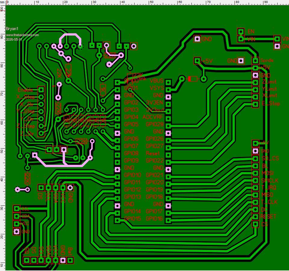 Took the screen shot in test mode and now everything should be right pico 2 board.zip Regards Bryan Edit: when I posted this thread and looked at the picture I saw I didn't do the ground plane edit on the GND for the I2C connector so it's done now Edited 2026-05-11 10:59 by Bryan1 |
||||
| Bryan1 Guru Joined: 22/02/2006 Location: AustraliaPosts: 2136 |
Well very close to finishing the X axis mount and silly me hole sawed to big a hole for where the mount bolts on so decided well as my mig welder does work now used that on the 110 amp setting I tested it with . After tacking plenty around the core so it would stay flat welded the first side with no problems now when I went to do a hot pass on the rear side got within 10mm of finishing the weld and the 16 amp circuit breaker in my inverter tripped.So for powering the mig in future I think I need a higher rating pair of circuit breakers as the new 16 amp ones doesn't look to be enough when welding a long run. Anyway for the chain alignment I found 3mm spacing out for the mount from the cast iron face does align both sprockets nicely Now after tapping 4 off 6mm holes for the mount found only had 3 off 6mm cap screws left  so just after 5pm that was enough for the day. so just after 5pm that was enough for the day. |
||||
| mozzie Guru Joined: 15/06/2020 Location: AustraliaPosts: 400 |
G'day Bryan, Looks like things are proceeding nicely except being 1 bolt short  I found the version of the limit input circuit I will be using on my systems here, this is better than the one above: 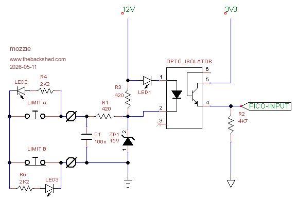 LED 1 is on when the limits are closed (normal) and off when open (tripped) LED 2/3 are high brightness across the limits and indicate a trip condition. It will be interesting to see how a chain drive goes, I made the mistake of going gear reduction on the coil winder (its what I could find) and it sounds like a machine gun. Tooth belt will be the next try. Not sure if a "D" curve breaker will fix that problem, they are great for motor start applications but you might be on the end of the delay curve with the welder. 20A might be the solution. Hope to get back to working on my machines shortly. Regards, Lyle. Edited 2026-05-11 23:23 by mozzie |
||||
| The Back Shed's forum code is written, and hosted, in Australia. | © JAQ Software 2026 |
