
|
|
Forum Index : Microcontroller and PC projects : Explore64 (Geoff’s MM+ module)...
| Author | Message | ||||
| Zonker Guru Joined: 18/08/2012 Location: United StatesPosts: 772 |
Ok.... It took a couple of days of "spare time", but I got a "hard build" of the 7" unit with Beeper, SD Card and Keyboard glued together and am happy to report, all seems to be working as expected... 
Will next try out playing around with the SD Card things... P.S. - The on-display editor is just awesome..!! I love the "total package" thing  |
||||
Grogster Admin Group Joined: 31/12/2012 Location: New ZealandPosts: 9975 |
@ Rob - wonderful!!!!
One thing that has been really annoying me, is having to unplug and replug, and restart TT. Not an issue if you do it once or twice, but if more then that.... Excellent tool - I vote that this info be in a thread of it's own - many would find it very useful. EDIT: Just tried this, but it does not work - for me.  Exact same problem - VCP vanishes, and you can't get it back, CTRL+F1 does nothing, have to power down, remove MM+, replace MM+ and restart TT. Exact same problem - VCP vanishes, and you can't get it back, CTRL+F1 does nothing, have to power down, remove MM+, replace MM+ and restart TT.
Any idea why this is not working for me? EDIT: Here is a shot of how I have the files configured: 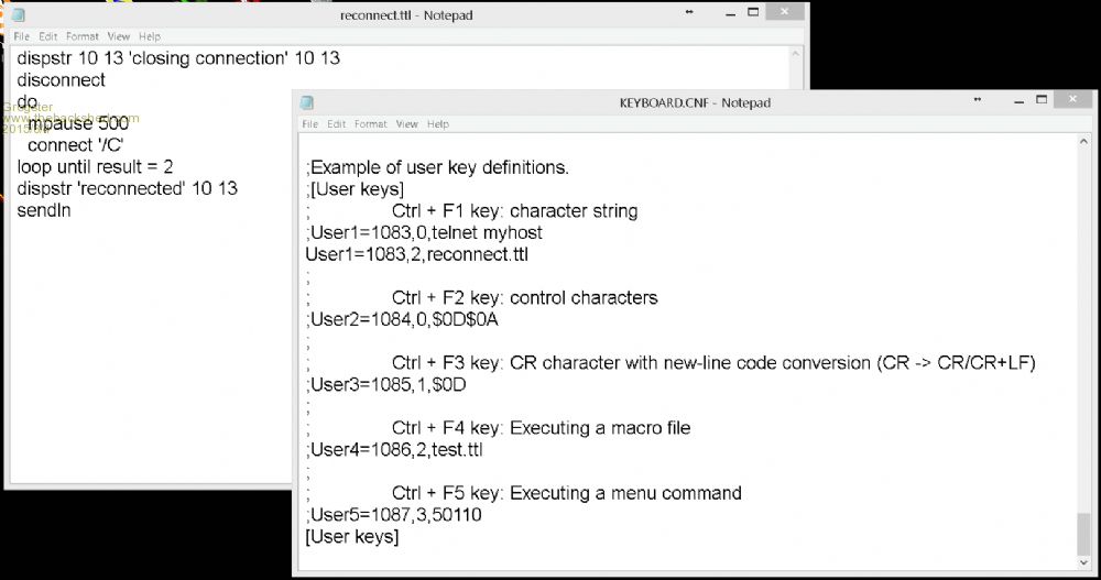
Also I should point out that I never get either of the prompts at ANY point in the process. I am guessing that "Closing connection" and "Reconnected" should be showing up as prompts in the TT window, yes? If that is the case, I never get them. This is what I am doing step by step: 1) Establish orriginal connection to MM+ [OK] 2) Press RESET on MM+ [OK] 3) VCP gone in TT [OK] 4) Hold CTRL and press F1 [OK] 5) "Closing connection" prompt [FAIL] 6) "Reconnected" prompt [FAIL] Smoke makes things work. When the smoke gets out, it stops! |
||||
| robert.rozee Guru Joined: 31/12/2012 Location: New ZealandPosts: 2528 |
aha, you need to remove the ";" before "[user keys]" as well! it took me a couple of hours to get the incantations just right, teraterm is quite finicky about things being just right. cheers, rob :-) |
||||
| Grogster Admin Group Joined: 31/12/2012 Location: New ZealandPosts: 9975 |
AWESOME - thanks for that, Rob. 
...one rotten semi-colon later..... 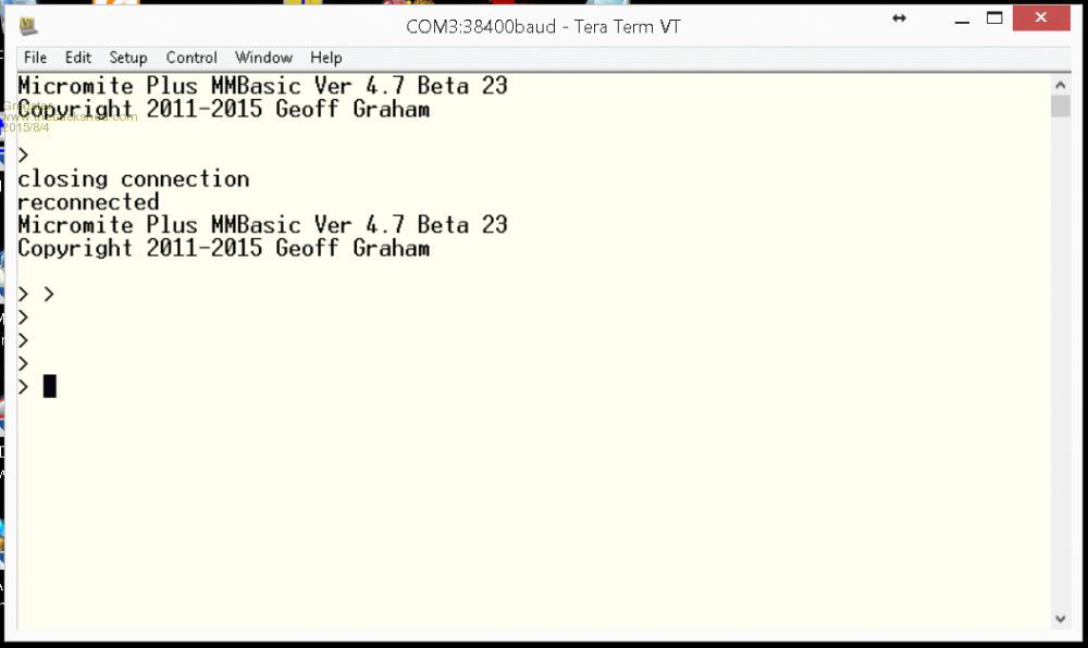
Smoke makes things work. When the smoke gets out, it stops! |
||||
| Geoffg Guru Joined: 06/06/2011 Location: AustraliaPosts: 3362 |
This is BRILLIANT Rob. It will save me a huge amount of time in development. Thanks, Geoff Geoff Graham - http://geoffg.net |
||||
| Grogster Admin Group Joined: 31/12/2012 Location: New ZealandPosts: 9975 |
Rob should post this handy mod as a separate thread. Who's with me? Smoke makes things work. When the smoke gets out, it stops! |
||||
| robert.rozee Guru Joined: 31/12/2012 Location: New ZealandPosts: 2528 |
i am flattered! BobD (Bob Denton) has sent me a nicely written up set of instructions as a PDF, attached here for anyone who would like to keep a copy or add to the archives. 2015-08-04_094221_Easy_reconnect_of_USB_port_to_TeraTerm_after_client_reset.pdf there are a few other neat tricks that TeraTerm can be set up to do that may also be useful. it is possible to turn the modem control lines on/off and send a break signal. the micromite+ could potentially respond to this internally to do things like resetting itself (if the USB code carries on running after a crash), sending internal interpreter debug information out a spare serial port or even saving it to an area of onboard flash, etc. the commands are: setdtr <flag> setrts <flag> sendbreak while the micromite+ would need to respond to these events internally (as there are no physical modem wires present), the physical lines DTR and RTS could be used with a MX170-based micromite (connected via a USB to serial bridge) to manipulate the reset pin. TeraTerm can also respond in 'complex' ways to command sequences sent to it. when i worked at one place, we had TeraTerm set up to upon request download the current date/time to an embedded system that had no onboard RTC. for more info, see: http://ttssh2.osdn.jp/manual/en/macro/ cheers, rob :-) |
||||
| Greg Fordyce Senior Member Joined: 16/09/2011 Location: United KingdomPosts: 153 |
I've figured out that it is not possible to use the SD card slot on the ssd1963 display if your E64 board has the sd card slot with pin 14 connected to the card detect pin (standard configuration). That's fine by me but I found this on page 6 of this thread and don't understand why this would be necessary? Doesn't this pin go straight between the sd card socket and this pin? If that is the case then it should be fine to leave SD_CS unconnected from anything? I suppose the only problem would be if someone inserted a SD card on the ssd1963? Another question, on page 28 of the Advanced Features manual it has this. Next, connect a pizeo buzzer from pin 50 of the Micromite Plus to ground (pin 50 has a 30mA drive capability
and this should be enough to operate most pizeo buzzers). This will be used be used to generate a click sound when controls are touched, it is optional but the audible feedback makes using the advanced controls more intuitive. The touch controller must be made known to MMBasic with the following command: OPTION TOUCH 14, 21, 50 I need pin 50 for SPI 1 but if I am reading the microchip datasheet correctly pin 44 also has a high drive output. Can someone confirm that pin 44 could also be used to drive a piezo buzzer directly? Thanks, Greg |
||||
lew247 Guru Joined: 23/12/2015 Location: United KingdomPosts: 1709 |
I've read through this post and I can't find it Does anyone know the pins needed to connect to an SSD1963 display? my mind has gone blank on what' needed to connect the display up Also can anyone tell me the distance in mm between the 2 rows of pins? I want to make a board that will plug directly onto an SSD1963 and have one of these plugged into it |
||||
palcal Guru Joined: 12/10/2011 Location: AustraliaPosts: 2039 |
Hi Lew, The MM+ manual has the pinout on page 13. The pin separation is .1" (2.54mm) Paul. "It is better to be ignorant and ask a stupid question than to be plain Stupid and not ask at all" |
||||
| lew247 Guru Joined: 23/12/2015 Location: United KingdomPosts: 1709 |
Thanks Paul, I've read that numerous times over the past week looking for various things and never spotted it The pin spacing I'd like to know is the horizontal spacing between the E64 rows of pins |
||||
| palcal Guru Joined: 12/10/2011 Location: AustraliaPosts: 2039 |
OK just measured my board and that spacing is .9" or 22.86mm. Paul. "It is better to be ignorant and ask a stupid question than to be plain Stupid and not ask at all" |
||||
| lew247 Guru Joined: 23/12/2015 Location: United KingdomPosts: 1709 |
Thanks Paul |
||||
| Grogster Admin Group Joined: 31/12/2012 Location: New ZealandPosts: 9975 |
I drew this ages ago, sorry you had a hard time finding it anywhere. 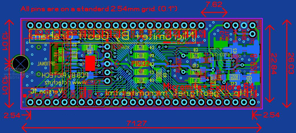 Smoke makes things work. When the smoke gets out, it stops! |
||||
| lew247 Guru Joined: 23/12/2015 Location: United KingdomPosts: 1709 |
Thank you so much |
||||
| lew247 Guru Joined: 23/12/2015 Location: United KingdomPosts: 1709 |
On my Explore64 I don't have a Jumper to enable USB power Am I safe to power the unit via the 5V in pin or will this damage the unit? |
||||
Azure Guru Joined: 09/11/2017 Location: AustraliaPosts: 446 |
What version of PCB do you have? You should be OK as long as you do not connect the USB cable while you are powering it from an external 5V. |
||||
| Grogster Admin Group Joined: 31/12/2012 Location: New ZealandPosts: 9975 |
Agreed. Yes, you can power the module from the 5v pin, but as Azure says, DON'T connect the USB at the same time. Technically speaking, you CAN do both, so long as J1 is NOT installed, as that will isolate the USB 5v from your external 5v. The USB 5v comes into the module, goes via J1 to the input of the 3v3 voltage regulator. The 5v pin on the module goes directly to the input of the 3v3 voltage regulator. Smoke makes things work. When the smoke gets out, it stops! |
||||
| The Back Shed's forum code is written, and hosted, in Australia. | © JAQ Software 2026 |
