Notice. New forum software under development. It's going to miss a few functions and look a bit ugly for a while, but I'm working on it full time now as the old forum was too unstable. Couple days, all good. If you notice any issues, please contact me.
Ok, I gave up on reading values and now I can control it and get output, but the volume level is very low - will have to keep fiddling. I guess it's the gain settings or something but it doesn't seem to like anything greater than 0x0f for the volume controls.
If interested, this does work but, as I said, volume very low:
#!/bin/sh
# Main Source Selector 0x00 to SE1 i2cset -y 1 0x44 0x00 0x01
# Main loudness i2cset -y 1 0x44 0x01 0x40
# Soft Mute 0x02 to OFF and IIC only i2cset -y 1 0x44 0x02 0x03
Grogster Admin Group Joined: 31/12/2012 Location: New ZealandPosts: 9973
Posted: 12:53am 20 Nov 2016
Copy link to clipboard
Print this post
Yes, you DO need to twiddle the gain and input coupling settings.
I used the following code:
Const TDA7419=&H44 'I2C address of 7419 audio processor GAIN=&B10011000 '3dB input gain - see manual p31. SourceSelect (4,GAIN) 'Set source to SE0 SetMode (2,&B11111011) SetMode (7,0) 'Enable rear speakers SetMode (8,&B11111111) 'Set Subwoofer SetMode (9,&B11110111) 'Enable Subwoofer SetMode (16,&B11000000) 'Select AC couple mode READSETTINGS if SAV=0 then 'No saved settings, so use defaults SetMode(02,2) 'Mute first SetMode(09,0) 'Set Mixing Level SetMode(10,0) 'Set Att LF SetMode(11,0) 'Set Att RF SetMode(12,20) 'Set Att LR SetMode(13,20) 'Set Att RR SetMode(14,0) 'Set Mixing Level SetMode(15,0) 'Set Att Subwoofer SetMode(02,3) 'Unmute endif
And the relevant subs:
Sub SetMode (Funct, Parameter) I2C Write TDA7419, 0, 2, Funct ,Parameter If Debug Then Print Funct, Parameter, MM.I2C End Sub
Sub SourceSelect (Source,Gain) Parameter=Gain Xor Source SetMode 0, Parameter End Sub
I seem to recall that the key to getting the volume level up there, is in the AC coupling section - command byte 16, page 37, Table 18. Ensure you have the master volume set quite low before you play with the coupling settings, cos once you set this, it makes a DRAMATIC difference to the output volume......Smoke makes things work. When the smoke gets out, it stops!
I confirmed it was the setting of the Spectrum analyzer/clock source/AC mode register that made all the difference with the volume issues I had been having.
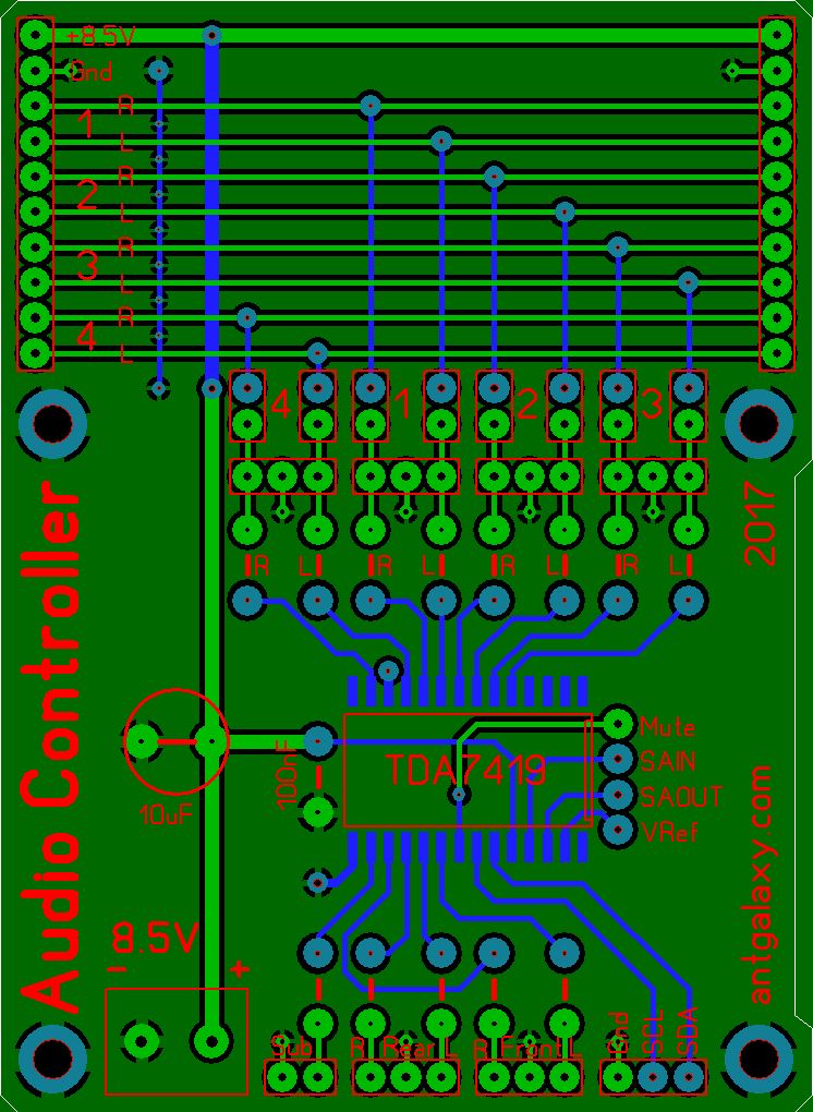
Here is the board I've come up with so far - can you spot any issues? Any suggestions?
I want to be able to link 4-6 of them together so they've got common inputs which can be individually disconnected by jumpers. Do you think there will be an issue sharing the inputs across multiple boards?
Each board will have its own RPi for control and its own amplifier unit. The RPis will play MP3s using the Music Player Daeomon (https://www.musicpd.org/), and a web interface for phone/tablet/PC which I've started building with PHP back end and Javascript front end.
Thanks for your help,
David
Grogster Admin Group Joined: 31/12/2012 Location: New ZealandPosts: 9973
Posted: 02:47pm 24 Nov 2016
Copy link to clipboard
Print this post
Hello fellow Sprint Layout user!
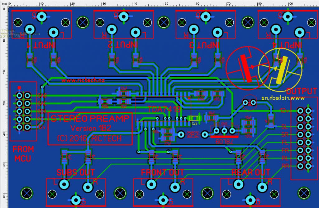
I can send you the .lay6 file for the preamp board I was using, if you would like to look at it, or use it as the basis of a change to suit your requirements.
I seem to recall that the local supply to this chip was quite critical. I would recommend separate on-board regulators for each 7419 chip, as if you have a 8.5v bus voltage, feeding all the chips natively voltage-drop could cause odd things to happen....
Note in my image above, which is pretty much a copy of the datasheet anyway, I have used a 9v regulator, and a series resistor and decoupling caps for the PSU.
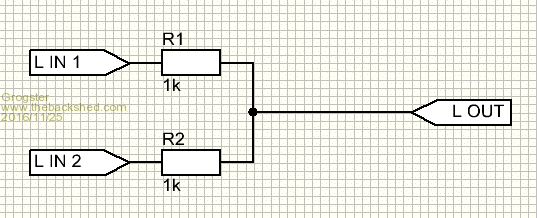
As to the mixing, I can't see any loading resistors for your mixing, but perhaps they are just not labelled. If you are going to be mixing several input signals before sending them through the 7419(or any other audio preamp etc), then you should have loading resistors - just a series resistor from each audio line - 1k or so would do.
The idea is just so that you are not effectively shorting out different audio sources by connecting them DIRECTLY together via the jumpers etc, which might otherwise upset the audio output stage of the connected device.
Edited by Grogster 2016-11-26Smoke makes things work. When the smoke gets out, it stops!
HankR Senior Member Joined: 02/01/2015 Location: United StatesPosts: 209
Posted: 05:41pm 24 Nov 2016
Copy link to clipboard
Print this post
David,
I'm not positive what you're thinking, but my guess is one source feeding paralleled inputs from 4 to 6 preamps with their associated power amps and speakers.
Is that correct?
If that's the case, I don't see a problem. The worst that could happen is that if the source is an unusually high impedance there might be a little signal drop due to the loading caused by driving multiple preamp inputs.
I think I'd be confident that feeding all these from one regulated supply would be okay, but Grogster's conservative approach with separate regulators is certainly not unreasonable. These are low level circuits that don't produce much signal power.
I'm going to risk sharing the voltage regulator across all 4 boards - for the sake of simplicity and because I don't have the parts here. Hopefully all is well, but if not I will have to order some parts and another set of boards.
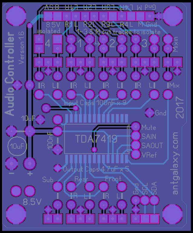
Yes Hank - I want to share some audio line level inputs between all four of these boards. Which I have now modified so they will stack instead of having in and out connectors. It'll be much simpler this way - I'll use the Arduino style headers with long pins protruding below. So hopefully that works also.
It's all a learning curve - coming together slowly. I'll keep you posted. Here is the latest version of the board - ordered from ShenZhen2U just now. Can't wait for this delivery!!!
Grogster Admin Group Joined: 31/12/2012 Location: New ZealandPosts: 9973
Posted: 05:18pm 27 Nov 2016
Copy link to clipboard
Print this post
Good luck. Please do post back with your results.Smoke makes things work. When the smoke gets out, it stops!