
|
|
Forum Index : Microcontroller and PC projects : Flash 3 common catode LED lamps.
| Author | Message | ||||
| PeterB Guru Joined: 05/02/2015 Location: AustraliaPosts: 669 |
Volhout & Tony Unfortunately Bob wants to use an existing P chan. FET. (I hope I've got it the right way round) and that means a voltage above his existing +ve rail. Hence the bootstrap and so it goes. I think he is stuck with the VOM1271. But I could be wrong  Peter |
||||
| Mixtel90 Guru Joined: 05/10/2019 Location: United KingdomPosts: 8911 |
Very simple, Volhout. It uses P-channel mosfets - but he wants to use N-channel. Sorry Bob, I wasn't intending to get at you in any way. It's just that there are so many variations on this theme now that it's getting a bit much. :) I *did* read the original thread right at the beginning. All of it, believe it or not. If you have a single 28v supply, with no other way of obtaining 5v for the arduino other than via a 7805 then that fixes the arduino -ve to be at the same voltage as the cathode of the LEDs and PeterB's last circuit can't be used. Right, I'll have one final attempt to solve this and I'll leave you alone, Bob. :) * Single 28v supply. Common cathode LEDs. N-channel mosfets. Arduino -ve is the same as 28v -ve - they share a common 0v in other words. * The mosfets *have* to be used as source-follower high side drivers. You can't do anything else with them simply because they are N-channel and you have common-cathode LEDs. Because of this the gate *has* to go positive to turn on the mosfet. * The mosfet gates *need* an absolute minimim of +4v relative to their source before they will start to turn on. In order to stay on the gate has to stay at that voltage. *The voltage at the source is going to go up to at least 24v with the LED lit, so the gate will need to stay at *over* 28v. This is the bit that concerns me about all the bootstrap circuits. The capacitor has to hold the gate voltage higher than 28v for the full "on" time of the LED, yet has to fully charge during the "off" time. You may need to play with the values. They will depend on your flash rates. * Unless a bootstrap is used then an additional way to exceed 4v relative to the mosfet source *has* to be found otherwise it simply can't be done using N-channel mosfets and everything stops here. That's not just being negative on my part, it's the way electronics works I'm afraid. * There are several ways to exceed the 4v minimum that's necessary. You can use an isolating dc/dc converter to get 5v and put the output "on top" of the 28v supply to give a 33v rail. You can add another 5v power supply (which is the same thing). In either case you can then pull the gate up to that to switch the mosfet on. IMHO there is no other sensible way out of this than to use the photovoltaic opto coupler mentioned previously, or something very similar to it. That device is designed for exactly this situation. It puts a voltage exactly where it's needed between the source and the gate, so it doesn't matter what your load is like. They *will* work, perfectly, first time. There's no tweaking of values to be done. That's my 2 penn'orth done now. I simply can't think of any other way to do it given the constraints of the specification and available components. I hope it's been of some use. :) Mick Zilog Inside! nascom.info for Nascom & Gemini Preliminary MMBasic docs & my PCB designs |
||||
| PeterB Guru Joined: 05/02/2015 Location: AustraliaPosts: 669 |
OOPS I did get that wrong didn't I. That's my fist mistake for this year.  Peter |
||||
| Volhout Guru Joined: 05/03/2018 Location: NetherlandsPosts: 5931 |
So, what is this? Bob has to build 22 LED drivers for 3 color common cathode power LED's (when I am correctly informed). And he needs to use IRF520 mosfets (need ?). Common cathode LED's and IRF520 N-channel MOSFET's are not a good match. Either use Common Annode LED's -or- P-channel MOSFET's. A P-channel MOSFET (60V/2A) cost a USD 0.40 at Farnell in single QTY's. I doubt whether.. 1/ Bob is a "troll", keeping us occupied (aka challenged). 2/ Bob is not aware that by keeping the IRF520's he is increasing the total cost (all the extra circuits needed to use the IRF520's), and decreasing reliability (let's be honest, stacking voltages...not going to be very reliable). 3/ The VOM1271 will NOT allow PWM (dimming of the LED's). Its slow -> pure ON-OFF. 4/ Bob has been given a "challenge" to drive CC LED lamps with N-channel FET's (school challenge ?). And needs to deliver a circuit diagram. Anyway... if Bob insists on using the IRF520's ad CC LED lamps, give him a circuit that 100% guarantied to work. Use an off-the-shelf isolated DC-DC convertor to create 5V (or preferably 9V) from 28V. Connect this DC-DC convertor to 28V (so you get 33V or more (*)) and use an opto coupler circuit similar to the one proposed in the PLC circuit to drive the N-channel FET gate from 33V. Do separate logic from power. And it is not cheap. And it is guaranteed to work. Also with PWM (that is: 500Hz Arduino PWM, not 30kHz PWM). Regards, Volhout (*) technically best would be to connect the DC-DC convertor to the Source of the N-channel FET, but then you need one DC-DC per IRF520 FET. PicomiteVGA PETSCII ROBOTS |
||||
| Mixtel90 Guru Joined: 05/10/2019 Location: United KingdomPosts: 8911 |
As far as I know (at least I don't remember seeing it) there is no requirement for PWM, only LED flashing. The VOM1271 *appears* to be ideal. Unfortunately the LED off and on times aren't specified and will be decided on test later. Apparently he has some on order and will be able to set up a test rig to prove whether or not they will do what he wants. EDIT: Found it... So PWM isn't confirmed. The VOM has a very low current output that has to charge quite a big gate capacitance so, as you say, PWM is unlikely to work. Edited 2021-08-09 19:24 by Mixtel90 Mick Zilog Inside! nascom.info for Nascom & Gemini Preliminary MMBasic docs & my PCB designs |
||||
| Tinine Guru Joined: 30/03/2016 Location: United KingdomPosts: 1646 |
Already suggested, earlier in the thread but logical solutions are not to be considered.....needs to be ridiculously complicated to keep the thread going. |
||||
| Mixtel90 Guru Joined: 05/10/2019 Location: United KingdomPosts: 8911 |
Naturally :) Lovely idea, but unless you are happy with paralleling the drivers it isn't usable. IIRC the white LED is around 1A and the colours are less (I can't remember the figures off-hand. I think they were around 300mA). It might be ok if inputs & outputs were paralleled with a low value resistor on each output to help equalise current from the outputs. One of those things where if you have one it's worth a try. :) EDIT: White is about 900mA. Others are about 100mA so those are ok. EDIT EDIT: :) If you have managed to *fully* turn on the mosfet in that demo circuit that you showed (the one with the 10v supply) then you've been *very* lucky because your mosfet(s) are more sensitive than their spec suggests. You need to test that circuit at the full 28v driving a white 900mA LED. Beware, it may get hot without a heatsink. That's because it's not fully turned on because there isn't enough voltage between source and gate. You will need to increase the 1k resistor to, say, 27k to keep about the same current or that too will get very hot. Edited 2021-08-09 21:41 by Mixtel90 Mick Zilog Inside! nascom.info for Nascom & Gemini Preliminary MMBasic docs & my PCB designs |
||||
| bob.steel Senior Member Joined: 27/02/2020 Location: AustraliaPosts: 188 |
Jesus what a bloody f**kup ! Forget it I'll work with what I have . The rest is just bullsh*t fellas. Nobody gets it right. |
||||
| Mixtel90 Guru Joined: 05/10/2019 Location: United KingdomPosts: 8911 |
Sorry, Bob, but you asked for help. People have tried to help you and, I'm sure, will continue to do so if you ask. Most of the confusion has been through people offering what they consider to be the best engineered way to to it rather than a way to use your N-channel mosfets. That's unfortunate, but it's the sort of thing that happens. There is no "right" solution. Some are better than others, some may be ruled out on cost grounds or for other reasons. At the end of the day the most "right" solution is the one that fits *your* criteria and works for *you*. No-one here can tell you which that is. It's unlikely that anyone is going to do all the necessary development and testing that you need either. For a start they probably haven't got the components that you want to work with. They couldn't produce meaningful test results for you. Mick Zilog Inside! nascom.info for Nascom & Gemini Preliminary MMBasic docs & my PCB designs |
||||
| Tinine Guru Joined: 30/03/2016 Location: United KingdomPosts: 1646 |
It's always about temperature. These devices often have their inputs and outputs paralleled. Then we also need to consider duty cycle. Experience/intuition tells me that this device will not be stressed at all. |
||||
| Mixtel90 Guru Joined: 05/10/2019 Location: United KingdomPosts: 8911 |
It would make a great driver for the 100mA LEDs, able to handle three simultaneously. Unfortunately the maximum recommended total current, no matter how many drivers are used, is 350mA. I suppose that's a +VS pin limit. It might be ok if the white LED was pulsed, but not if lit continuously for any length of time. A channel could be used to source current into the base of a BJT PNP power transistor though, and use that for the white LED. just a base resistor and a turn-off resistor to it's emitter and job's a good 'un. Unfortunately it doesn't use any mosfets up. :( Mick Zilog Inside! nascom.info for Nascom & Gemini Preliminary MMBasic docs & my PCB designs |
||||
TassyJim Guru Joined: 07/08/2011 Location: AustraliaPosts: 6538 |
I can understand Bob's desire to use up the stock on hand but I am fashioned enough to reach for a TIP127 PNP Darlington. Current price around $1AU and add 50c for the NPN driver transistor and a couple of resistors... Jim VK7JH MMedit |
||||
| Mixtel90 Guru Joined: 05/10/2019 Location: United KingdomPosts: 8911 |
Plenty of drive current (>50mA even with 3x 100mA leds lit) available from a UDN chip, Jim. You only need a gain of 18 at most so a darlington is probably overkill. There may not even be 3 LEDs, only 2 (red/blue). A TIP32C should do it easily at less than half the cost. No driver transistor, just the UDN chip, 2 resistors and a TIP32C. That's all that's needed for a 900mA white and up to 3 100mA colours. All logic inputs into the UDN. All continuously rated. Will probably work with PWM too, if the frequency is kept down to something sensible. It appears that the UDN chip is no longer manufactured and is no longer listed by RS and Farnell. However, Toshiba have released the TBD62783A which is an excellent DMOS replacement with lower power dissipation. RS sell the through-hole DIP (PG) version for 8.65 UKP +vat for a pack of 10. You can get the TIP32C for 49p each. Ignoring postage, that's less than 2 quid +pcb for a complete driver package. Edited 2021-08-10 18:31 by Mixtel90 Mick Zilog Inside! nascom.info for Nascom & Gemini Preliminary MMBasic docs & my PCB designs |
||||
| Volhout Guru Joined: 05/03/2018 Location: NetherlandsPosts: 5931 |
Nice chip: TBD62783A At 50% duty cycle it can handle 170mA per channel (PG package, through hole). 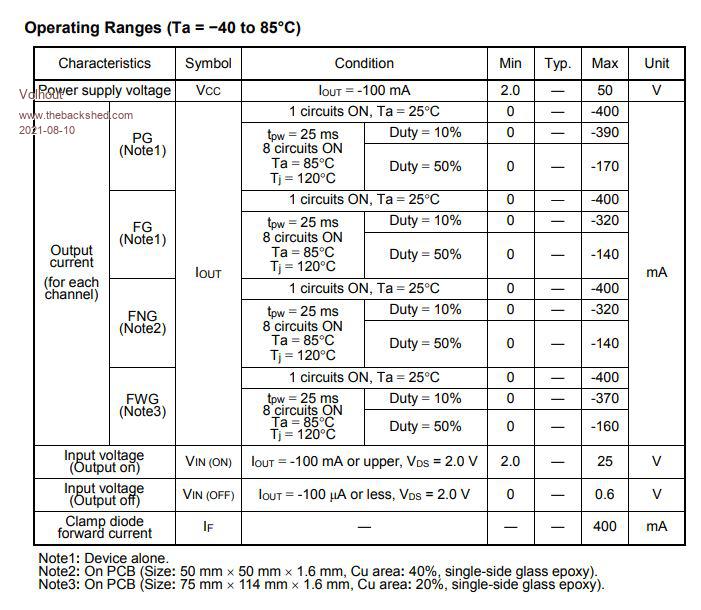 So a single chip solution seems possible. Use 1 channel for each of the 100mA colors Use the remaining channels parallel for the white channel (you can parallel mosfets). Bob, this is it.... PicomiteVGA PETSCII ROBOTS |
||||
| Mixtel90 Guru Joined: 05/10/2019 Location: United KingdomPosts: 8911 |
OOPS! My idea of driving a PNP from that chip doesn't work as I'd originally intended, sorry. It should be an NPN as an emitter follower. I'd forgotten that it's a high-side driver. I failed... :( The turn-off resistor should be to the emitter of course (top end of load should be ok. Output leakage is very low and won't light the LED). Base resistor could be about 330R. It just gives some protection to the chip output. Turn-off resistor, say, 10k. Luckily a TIP32C (NPN) is about the same price. :) You still have maximum total input current into the supply pin. You can't get 500mA from all 8 outputs at the same time, even if you could stay within the package power rating. They don't state that maximum current, but 500mA total would make sense for a single pin on a DIP package. Note that they show 400mA max output with one circuit ON. I don't think you can get 900mA *continuous* through the pin under any circumstances (not without sub-zero chilling anyway :) ). You may be able to get 900mA *short pulses*, but that's not what's wanted. Inputs are dead easy. Direct connection to the arduino pins. :) 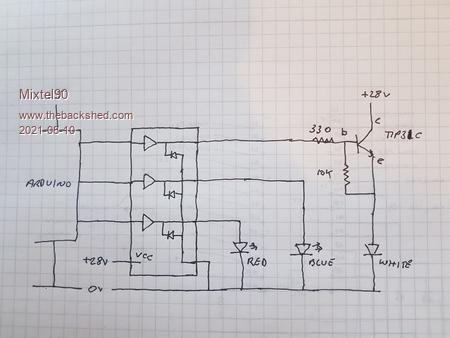 Edited 2021-08-10 20:15 by Mixtel90 Mick Zilog Inside! nascom.info for Nascom & Gemini Preliminary MMBasic docs & my PCB designs |
||||
| Tinine Guru Joined: 30/03/2016 Location: United KingdomPosts: 1646 |
The MC2981 (Micrel) appears to be the modern version. I guess that this is down to interpretation and I can't find where I once read that it's recommended to push no more than 2A @24v total at any time. This was when I was looking for something to allow me to PWM solenoid coils but I ended up going with the LMD18200 instead. |
||||
| Mixtel90 Guru Joined: 05/10/2019 Location: United KingdomPosts: 8911 |
The trouble is, "limited only by package power dissipation" is *very* vague. It's also only correct for a narrow range of "correct". A 100A surge current will prove that, even if it's only for a ns. The chip bonding wire on the positive supply pin is an excellent fuse. :) Assuming a single driver drop of 2v (within spec at anything over 100mA) a 500mA continuous load would already be 1W dissipation. Most through hole DIP packages aren't at all happy beyond about 1.5W. That Micrel MIC2981 is the worst so far for giving useful info. It doesn't even give the maximum package dissipation, never mind the maximum current into the Vs pin. :( EDIT: If the white LED incorporates its own current limiting, which I assume it does if it is supposed t work from a constant voltage, then any attempt to dim it is likely to fail. EDIT EDIT: I went back to the original UDN2981 data sheet. The package seems to be rated at 2.25W maximum. Any pushing of that will definitely require a heatsink on the chip. Vce is a nominal 2v for each channel. Maximum current through a single output is 500mA. Splitting the 900mA load across 3 outputs would give 1.8W total dissipation. With a further 0.2W dissipation for two other channels driving 100mA LEDs that's a total of 2.2W with all the LEDs on. In theory it *may* be possible to drive all the LEDs from a single chip, but the DMOS version will run cooler. The supply current would be 1.1A though and I can't find any data sheet confirmation that the source pin would be capable of this. These dissipation figures are based on Vce being 2v. It's likely to be slightly less (1.8v at 350mA and 1.6v at 100mA typ). Edited 2021-08-11 00:30 by Mixtel90 Mick Zilog Inside! nascom.info for Nascom & Gemini Preliminary MMBasic docs & my PCB designs |
||||
| Tinine Guru Joined: 30/03/2016 Location: United KingdomPosts: 1646 |
Just added a pack of 10 to my RS-Online basket....got me to the free shipping level  Edit: Just popped a 20R, 50W resistor in there as well  Edited 2021-08-11 01:35 by Tinine |
||||
| Mixtel90 Guru Joined: 05/10/2019 Location: United KingdomPosts: 8911 |
ooh! New toys! :) And that would probably be a nice warm dummy load. :) Mick Zilog Inside! nascom.info for Nascom & Gemini Preliminary MMBasic docs & my PCB designs |
||||
| Tinine Guru Joined: 30/03/2016 Location: United KingdomPosts: 1646 |
50w turned out to be back-ordered so switched to a 100W and ordered 2 instead of 1. Let's test this baby @2A+ |
||||
| The Back Shed's forum code is written, and hosted, in Australia. | © JAQ Software 2026 |
