
|
|
Forum Index : Microcontroller and PC projects : PicoMite V6.02.00 release candidates - Structured types
| Author | Message | ||||
| bfwolf Senior Member Joined: 03/01/2025 Location: GermanyPosts: 250 |
Good explanation!  I just took a quick look at the HD44780 datasheet and understood it. Does that mean the (parallel) LCD driver and the I2CLCD driver don't make any assumptions about the number of characters per line and also don't use automatic line breaks? That would be good in this case! It would mean that if you output 20 characters starting from line 1 / column 1 on a 16x2 display, the last 4 would end up in the "invisible display RAM" — but if one knows that, it's fine. And you simply always configure the HD44780 chip to '2-line display' by setting N=1 in the HD44780 command 'Function Set'?  |
||||
| JanVolk Guru Joined: 28/01/2023 Location: NetherlandsPosts: 384 |
Peter, The version you sent me yesterday has been working flawlessly all this time. I spent a whole day looking into my autorun problem with this version. I added a pause 1000 to the first line of the program, and it worked immediately. Now I'm doing a long-term test. Would this demonstrate operation with a level shifter or without external pullup resistors at 3V3 for an I2C LCD? I also did some testing with the new version V6.02.00RC6 with a level shifter, and it works perfectly. I also tested with a 2x16 LCD using a PCF8574A and a standard RP2040. LIST SYSTEM I2C indicates the correct I2C address, 3F, but the program returns an error. >run [5] I2CLCD INIT &H3F Error : 63 is invalid (valid is 32 to 39) Kind regards, Jan. |
||||
| JanVolk Guru Joined: 28/01/2023 Location: NetherlandsPosts: 384 |
Sorry, maybe a different problem? I see that the address should be &H38 or 56 decimal, and with LIST SYSTEM I2C it's 3F? So I adjusted this, but it doesn't help. I'll keep looking. [5] I2CLCD INIT &H38 Error : 56 is invalid (valid is 32 to 39) > list system i2c HEX 0 1 2 3 4 5 6 7 8 9 A B C D E F 00: -- -- -- -- -- -- -- -- -- -- -- -- -- -- -- -- 10: -- -- -- -- -- -- -- -- -- -- -- -- -- -- -- -- 20: -- -- -- -- -- -- -- -- -- -- -- -- -- -- -- -- 30: -- -- -- -- -- -- -- -- -- -- -- -- -- -- -- 3F 40: -- -- -- -- -- -- -- -- -- -- -- -- -- -- -- -- 50: -- -- -- -- -- -- -- -- -- -- -- -- -- -- -- -- 60: -- -- -- -- -- -- -- -- -- -- -- -- -- -- -- -- 70: -- -- -- -- -- -- -- -- -- -- -- -- -- -- -- -- > Kind regards, Jan. |
||||
| phil99 Guru Joined: 11/02/2018 Location: AustraliaPosts: 3316 |
Comparing the datasheets for the PCF8574 and PCF8574A chips the address ranges are different. The A version is &B0111000 to &B0111111 = &H38 to &H3F = dec 56 to 63. So even changing the A0 to A2 address pins won't help. The driver may need adjusting to make it work with that chip. |
||||
| JanVolk Guru Joined: 28/01/2023 Location: NetherlandsPosts: 384 |
I found a problem with this 2x16 I2C module. The pull-up resistors were missing. Now I've used another PCF8574A with address 27 hex and LIST SYSTEM I2C, but unfortunately, nothing appears on the screen. The other screen with the 2x16 I2C PCF8574A module has the 4k7 SMD resistors inserted, but still has 3F as the address, but nothing appears on the screen. An old kas.bas program with the latest firmware V6.02.00RC6 and an old LCDI2C subroutine with OPTION SYSTEM I2C GP20, GP21, SLOW, and address 3F (PCF8574A) works, the 2x16 LCD screen does work. Thanks, Phil99. The driver is the problem. Kind regards, Jan. |
||||
| JanVolk Guru Joined: 28/01/2023 Location: NetherlandsPosts: 384 |
Peter, I thought the RAM wasn't reset, but the date and time are reset when the power remains on? This also applies to the option autorun on,noreset. Even without the autorun option on, the date and time are reset. Pause 2000 ' Everything happens automatically with I2CLCD from version V6.02.00RC6. ' A 4x20 LCD2004 LCD screen. ' A level shifter between the RP2040 module and the LCD2004 with an I2C PCB. ' Or desolder the 4K7 pullup resistors and connect them externally to 3V3. ' No RTC time and date: date$="dd-mm-yyyy" and time$="hh:mm:ss" until power off. ' The SD CARD is mounted on the Raspberry Pi Pico RP2040 for a complete system. ' OPTION SYSTEM I2C RP20, RP21 ' For the I2C bus. See > HELP OPTION. ' OPTION SDCARD GP19, GP10, GP11, GP12 ' For the SD card. See > HELP OPTION. I2CLCD INIT &H20 ' Request address with: LIST SYSTEM I2C Do I2CLCD 1,C20,"B+ Westland" ' I2CLCD Y,X Y=Line no., X=Char no., C=Middle I2CLCD 2,C20,"Hobby Computer Club" I2CLCD 4,1, "Fr "+Date$+" "+Left$(Time$,5) ' Anything is possible with one line. Pause 1000 Loop > flash save 2 > option autorun 2,noreset > > time$="16:04:02" > date$="16-1-2026" > run Kind regards, Jan. |
||||
| matherp Guru Joined: 11/12/2012 Location: United KingdomPosts: 11603 |
Ther current version doesn't support addresses &H38 to &H3F. I'll include this in the next release. Other than that I don't understand what you are telling me. I've tested a 16x2 on &H27 and it works perfectly Edited 2026-01-17 02:53 by matherp |
||||
| JanVolk Guru Joined: 28/01/2023 Location: NetherlandsPosts: 384 |
Peter, Sorry, I'm completely wrong. I checked back to V6.00.03, where the date and time were already cleared after a reset. I thought it was the same as with PSRAM, where the RAM memory is retained after a reset, but that's a completely different story, as the memory is located in slots 1-5. Kind regards, Jan. |
||||
| matherp Guru Joined: 11/12/2012 Location: United KingdomPosts: 11603 |
V6.02.00RC7 PicoMiteV6.02.00RC7.zip This version tweeks the I2CLCD command to allow address ranges &H20 to &H27 and &H38 to &H3F. In addition it adds functionality to DEVICE BITSTREAM to allow a second pin to be specified and used OR the same pin to be used twice (WTF? - see below). The other change is to allow the Basic user to effectively specify a pin as open collector. When this option is set the pin is driven when a low signal is output and set to high-impedance when a high signal is output. Here is the manual for the enhanced command which is still fully compatible with the previous syntax. BITSTREAM_User_Manual.pdf In it are two expanded examples of use of the new facility. Using two pins, the first example generates a PS2 output allowing the PicoMite to act as a PS2 Keyboard or mouse. This is fully tested and I have posted a slightly enahanced version of the program here. Does this open up the way finally for a MMBasic standard gamepad? The second example uses the capability to specify the same pin twice to create an IR transmit output. The first use of the pin is to generate the 38KHz carrier and the second use ANDs the signal with it, effectively modulating the carrier as is required. I haven't wired up this to do a full test but the output looks perfect on the scope. This should allow the Basic user to create any IR protocol without having to resort to a csub and/or external electronics to AND two pins. The new functionality of DEVICE BITSTREAM should open up many new possibilities for complex communication protocols to be coded directly in Basic. NB: you can now also use BITSTREAM as a command without needing DEVICE Edited 2026-01-17 18:44 by matherp |
||||
| Mixtel90 Guru Joined: 05/10/2019 Location: United KingdomPosts: 8935 |
My dream... :) If you could wire-OR a PS2 keyboard and such a gamepad then the only thing stopping it would be a decent case and buttons/direction pad. Or maybe use a PS2 mouse input for a gamepad? Mick Zilog Inside! nascom.info for Nascom & Gemini Preliminary MMBasic docs & my PCB designs |
||||
| phil99 Guru Joined: 11/02/2018 Location: AustraliaPosts: 3316 |
The new Bitstream will be very useful, thank you. IR Tx from a single pin can be done with the original Bitstream but is more complicated. Getting Philips RC5 and RC6 Manchester protocol into the Bitstream with the carrier was a brain strainer. See here on FotS |
||||
| ville56 Guru Joined: 08/06/2022 Location: AustriaPosts: 547 |
deleted ... Edited 2026-01-18 02:10 by ville56 73 de OE1HGA, Gerald |
||||
| JanVolk Guru Joined: 28/01/2023 Location: NetherlandsPosts: 384 |
Thank you, Peter. The LCD screen now works with the other addresses, and the 2x16 screens also work now. My existing greenhouse program worked after changing from LCDI2C to I2CLCD; I only had to adjust I2CLCD INIT. After that, I deleted the old subroutines, and it still works, now with various sensors. After the update, I did have to reload the program from the SD card on the RP2040 because the memory and the A drive aren't erased after an update. (The command list has become longer, so I2CLCD has a different name.) I'm very happy with this update, which makes it clearer by putting more functionality on a single line of the LCD in a program, instead of everything on a separate line. It's also helpful for beginners to get a simple LCD screen working with just a few lines of code. I still have a lot to explore in the existing PicoMite Basic code. Jan. |
||||
| Volhout Guru Joined: 05/03/2018 Location: NetherlandsPosts: 5975 |
@Peter, As much as I like you improving 6.02.00 with additional features, could you please revert back ? On the RP2040 microcontroller version, we lost 48k of A:/ drive on rc7 versus rc3. This is killing Game*Mite. To me it does not look like the additional I2CLCD commands and BITSTREAM would take that much flash, but fact is that it does. Thank you in advance, Volhout PicomiteVGA PETSCII ROBOTS |
||||
| bfwolf Senior Member Joined: 03/01/2025 Location: GermanyPosts: 250 |
This too would be a long-term indication that it would be good to have DLLs that could be included, for example, with DECLARE FUNCTION Name [(ParameterList)] LIBRARY 'and anywhere additionally LIBRARY "dllfilename.library" , just as it was done in AmigaBasic and in a very similar way in Visual Basic. For example in VB: Declare Function GetUserName Lib "advapi32.dll" Alias "GetUserNameA" (ByVal lpBuffer As String, ByRef nSize As Integer) As Integer See also my post: https://www.thebackshed.com/forum/ViewTopic.php?TID=18499&PID=249169#249169#249169 By the way: While searching, I saw that the FreeBASIC compiler does something similar: https://www.freebasic.net/wiki/KeyPgDeclare @Peter: Take a look at this section (FreeBASIC):  Type T Declare Constructor [ param_list ] Declare Destructor Declare Sub name [ param_list ] Declare Function name [ param_list ] [ Byref ] As return_type Declare Operator name [ param_list ] [ [ Byref ] As return_type ] Declare Property name [ ( [ param_list ] ) ] [ [ Byref ] As return_type ] End Type You know what I'm referring to, right? Edited 2026-01-19 07:47 by bfwolf |
||||
| ksinger Regular Member Joined: 06/01/2026 Location: United KingdomPosts: 70 |
@Peter: Hi I am Kilian, a maximite veteran, made the first proof of principle of a colour maximite (https://hackaday.com/2012/05/18/a-color-maximite-for-glorious-3-bit-basic/). I am also really happy that my proposal of adding the mod file format was implemented right away. I love those files from my amiga time. Thanks for accepting my pullrequest but there was a logic inversion error still. I pushed https://github.com/UKTailwind/PicoMiteAllVersions/pull/20 which fixes it. We will soon have a project day and I want to present the picomite as a nice educational computer. That's why I ported gtypist on it also with support for west european special characters. I also made a real fast clone of pong, arcanoid which shows how the game would work when we would have quantum superposition states. Currently I am trying to make a mario clone which teaches vocabularies. But on that way I did not find a good way to detect pixel exact background collisions (not only sprite sprite collisions). So that was the reason for my other pullrequest. The idea is that I added sprite(b,spritenum) which gives 0 if there is no collision with the exisiting non sprite objects on the screen. Then sprite(b,spritenum,0...3) gives the amount by which an overlap is generated in pixel. This made it quite fast to get the sprites moving without stutter. I also realised that blit framebuffer from,to does not take layer 2. But I could workaround this. sprite(b,spritenum,0...3) is quite great because in case of collision you can just move the sprite back with the given numbers to avoid the collision again. I realized that I was able to use the exact same board as I had already built for https://github.com/fhoedemakers/pico-infonesPlus and no changes besides audio needed. They actually put the audio into the hdmi stream. so I just added the filters to get sound. And it worked very nicely. Edited 2026-01-19 09:02 by ksinger |
||||
| phil99 Guru Joined: 11/02/2018 Location: AustraliaPosts: 3316 |
Had some difficulty with the PS/2 Scan Code example in the "BITSTREAM Command User Manual" With some minor additions got it to run, though have not plugged it into anything yet. Connected to a 74HC595 with 8 LEDs it makes a nice light show ;) ' Transmit a PS/2 scan code Sub PS2_Send(scanCode As Integer) Local bits(10) As Integer Local clkTiming(30) As Integer Local datTiming(30) As Integer Local clkIdx As Integer = 0 Local datIdx As Integer = 0 Local currentData As Integer = 1 ' Data starts HIGH (hi-Z) Local dataTime As Integer = 0 Local bitVal As Integer Local i As Integer Local parity As Integer Local count As Integer = 0 ' PS/2 timing (microseconds) '<---------------this section added Local CLK_LOW = 40 ' Clock low time Local CLK_HIGH = 40 ' Clock high time Local INIT_DELAY = 50 ' Initial delay ' Calculate parity (odd parity) For i = 0 To 7 If (scanCode >> i) And 1 Then count = count + 1 Next i parity = (count + 1) And 1 ' Build the 11-bit frame: Start, D0-D7, Parity, Stop bits(0) = 0 ' Start bit For i = 0 To 7 bits(i + 1) = (scanCode >> i) And 1 Next i bits(9) = parity bits(10) = 1 ' Stop bit ' First bit - data changes before first clock falling edge bitVal = bits(0) If bitVal <> currentData Then datTiming(datIdx) = INIT_DELAY - 5 : datIdx = datIdx + 1 currentData = bitVal dataTime = 5 Else dataTime = INIT_DELAY EndIf ' First clock transitions clkTiming(clkIdx) = INIT_DELAY : clkIdx = clkIdx + 1 clkTiming(clkIdx) = CLK_LOW : clkIdx = clkIdx + 1 ' Process remaining bits (1-10) For i = 1 To 10 bitVal = bits(i) If bitVal <> currentData Then datTiming(datIdx) = dataTime + CLK_LOW + 5 : datIdx = datIdx + 1 currentData = bitVal dataTime = CLK_HIGH - 5 Else dataTime = dataTime + CLK_LOW + CLK_HIGH EndIf clkTiming(clkIdx) = CLK_HIGH : clkIdx = clkIdx + 1 clkTiming(clkIdx) = CLK_LOW : clkIdx = clkIdx + 1 Next i ' Return data to HIGH if needed (ensure even transitions) If currentData = 0 Then datTiming(datIdx) = dataTime + CLK_LOW + CLK_HIGH : datIdx = datIdx + 1 EndIf If (datIdx And 1) = 1 Then datTiming(datIdx) = 50 : datIdx = datIdx + 1 EndIf Print "clkTiming() = "; : Math v_print clkTiming() Print "datTiming() = "; : Math v_print datTiming() ' Transmit using open-collector mode Bitstream CLK_PIN, clkIdx, clkTiming(), 0, DAT_PIN, datIdx, datTiming(), 0 End Sub ' Initialize and send scan code for 'A' CLK_PIN=1 : DAT_PIN=2 '<-----------------------added, choose your pins Dim integer n SetPin CLK_PIN, DOUT SetPin DAT_PIN, DOUT For n=0 To 50 PS2_Send(&H1C+n) Print "Input scan code = &H";Hex$(&H1C+n) Print "PS/2 scan code sent!" Pause 500 Print :Print Next Edit. The console optput when connected to GP8,9 of another Pico. > w2cxde43 vftr5nbhgy6mju78,kio09./l;p- > Edited 2026-01-19 17:33 by phil99 Footnote added 2026-01-20 14:08 by phil99 During testing I changed the Bitstream output from 'open collector' to push-pull. Change it back with :- Bitstream CLK_PIN, clkIdx, clkTiming(), 1, DAT_PIN, datIdx, datTiming(), 1 |
||||
| Mixtel90 Guru Joined: 05/10/2019 Location: United KingdomPosts: 8935 |
Just musing: On a Picomite you probably can't have DLLs as the user program is in flash and RAM is tight, unless you give up screen resolutions, layers etc. There's nowhere to load them from disk and there's no OS to keep track of them. In the dim and distant past the Nascom had a single address in RAM that normally pointed back into the EPROM. You could change that address to point to a user command table terminated by that same jump. This optional table acted like an extension to the EPROM. Each entry consisted of the command letter and an address for the routine. When commands were entered the user table was tested first, followed by the main commands. This allowed new user commands to be written, including some that replaced the system ones. Now, perhaps this might be a possibility. The jump table and MMBasic extensions could be stored in the Library flash. Ok, you lose the Library but you can't have everything and there would be zero impact on user space or the heap. It would be initialised by setting the Library flash area to be an Extensions flash area, creating the table. Just a thought. Mick Zilog Inside! nascom.info for Nascom & Gemini Preliminary MMBasic docs & my PCB designs |
||||
| matherp Guru Joined: 11/12/2012 Location: United KingdomPosts: 11603 |
For the avoidance of doubt. There is NO change between RC3 and RC7 in the size of the firmware. In both cases it is 53 16Kbyte blocks = 848Kbytes and the size of the A: drive is identical (6.01.00 was 816KBytes) . The images are taken from firmware downloaded from this thread. What did change before RC3 is that I finally implemented GUI controls properly meaning that if OPTION GUI CONTROLS isn't set they use no memory. This released extra memory which was added to the MMbasic heap increasing it, in the case of the RP2040 Picomite from 124K to 132K which gives more space for arrays, framebuffers etc. This also increases the maximum program size. As a result the flash image of the program and the flash slots all use more memory reducing the size of the A: drive. Taken together compared to 6.01.00 the size of the A: drive is reduced by exactly 65536 bytes = 64K- just less than 10%. I do not intend to reverse these changes, either to remove functionality from the RP2040 (possible savings 32768 bytes) or reducing the heap size (the other 32768 bytes). I'm sorry Harm, but it is not reasonable to have development stopped by the ability to put x number of games on the A: drive just to support then Game*Mite. There are multiple Pico clones out there with more flash memory than the original Pico and of course the RP2350 is fully compatible and comes standard with 4Mb. If the original Pico is so important surely you can find a way to save some file space by crunching programs, swapping bmp to jpg etc. I am fully committed to ensuring the new releases are backwards compatible from a functionality perspective. As to DLLs - forget it. Software would have to be compiled separately, position independent and then somehow loaded into flash. There is zero chance that this is ever going to be looked at by me. 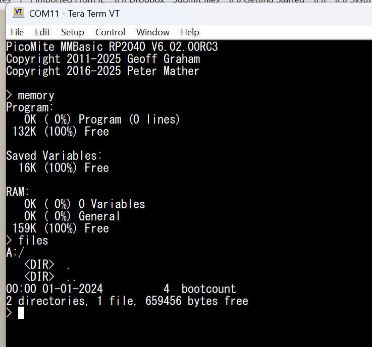 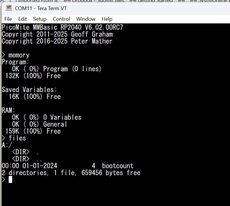 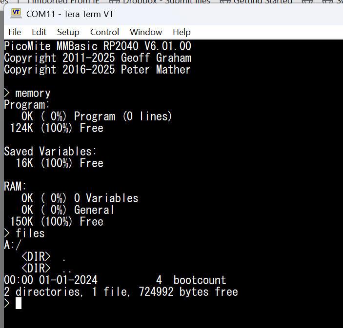 Edited 2026-01-19 18:55 by matherp |
||||
| matherp Guru Joined: 11/12/2012 Location: United KingdomPosts: 11603 |
Hi ksinger - welcome on board. Please can you explain more. Suppose I have a sprite 10x5 vertically above another sprite 10x5. I move the top sprite down in the y direction so that it overlaps the bottom sprite by 1 pixel in the Y direction. However, because they are both 10 pixels wide they overlap 10 pixels in the x direction. How exactly do I use your proposed function and what does it return? Please write some pseudo code so I can properly understand. The basic concept seems interesting and if we can make it work properly I'm happy to include something in this next release. |
||||
| The Back Shed's forum code is written, and hosted, in Australia. | © JAQ Software 2026 |
