
|
|
Forum Index : Microcontroller and PC projects : Stepper Project
| Author | Message | ||||
| PhenixRising Guru Joined: 07/11/2023 Location: United KingdomPosts: 1988 |
I had a bit of a tinker with it: 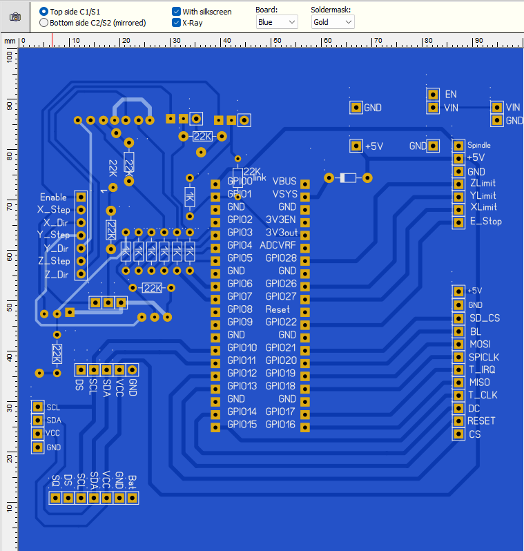 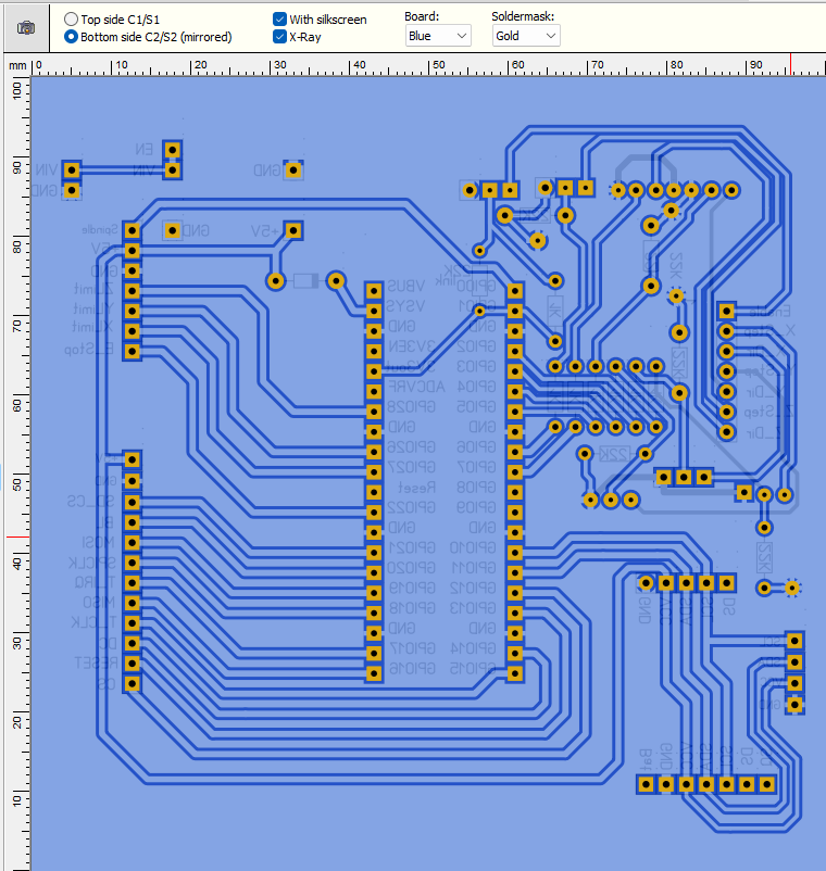 pico 2 board.zip Please check: Track widths Hole diameters (a bit inconsistent) Continuity (in case I messed up) Edited 2026-05-12 04:14 by PhenixRising |
||||
Bryan1 Guru Joined: 22/02/2006 Location: AustraliaPosts: 2136 |
Morning Guy's, Well still on my morning caffine intake  Now Phenix that board is looking way much better Now Phenix that board is looking way much better  and I'm looking forward to having a good look at it. and I'm looking forward to having a good look at it.Now with the limits Lyle that new circuit does look the goods mate and what I'm thinking the first job I will be doing once I setup the 2350A on the breadboard is set up the I2C on the zero so the zero can take of of the limits then when a limit is reached a I2C interrupt can send the control(val) number to the pico so action can be taken.This way your circuit can go on a new a new board with the zero for each axis while taking care of the battery management. Now here is where I am stumbling in my research on a previous page it was mentioned setick/ loop to move the axis in toggle mode. Now on reading setick in the manual it does set an interrupt and let one give a pulse value now as I have setup a number box on each axis that can be the value to use for the length traveled and maybe another number box put in for the feedrate so the uS value can go in the setick. Now for me trying to put this snippet into code would mean a days tinkering and still going nowhere so if a member could please help me out with this I can move forward with both the code and the project. Regards Bryan |
||||
| Bryan1 Guru Joined: 22/02/2006 Location: AustraliaPosts: 2136 |
Well just on lunchtime and got the chain drive setup good enough for the trial runs as I do still need to finish off the idler sprocket so it's adjustable.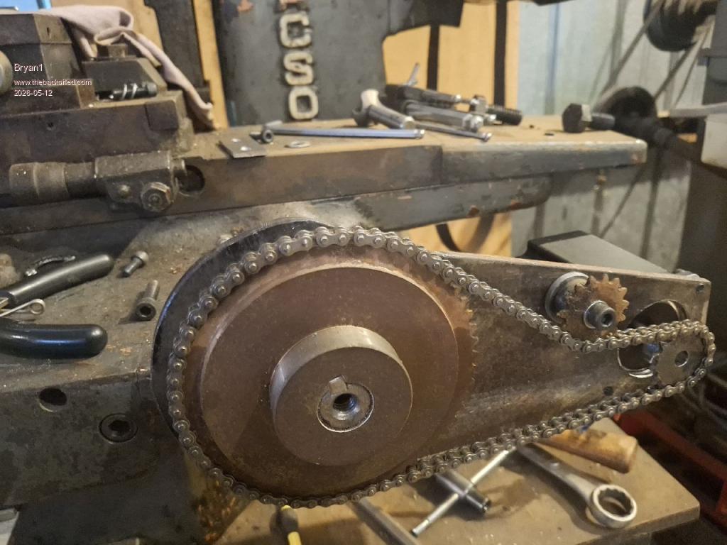 Regards Bryan |
||||
| Bryan1 Guru Joined: 22/02/2006 Location: AustraliaPosts: 2136 |
This afternoon mounted the DM556's on some MDF and attached it to the side of the work table. Got the Z axis all wired up so in the morning the X and Y axis will get done then time to redo my breadboard so the testing can start. Now for that clamp for the Z axis wire I just made it from a Nescafe 43 coffee tin where it was folded in half then each side got a some love tapping to stiffen it up. A short length of 1/2" copper pipe soon got the radius done and tek screw soon got it clamped. 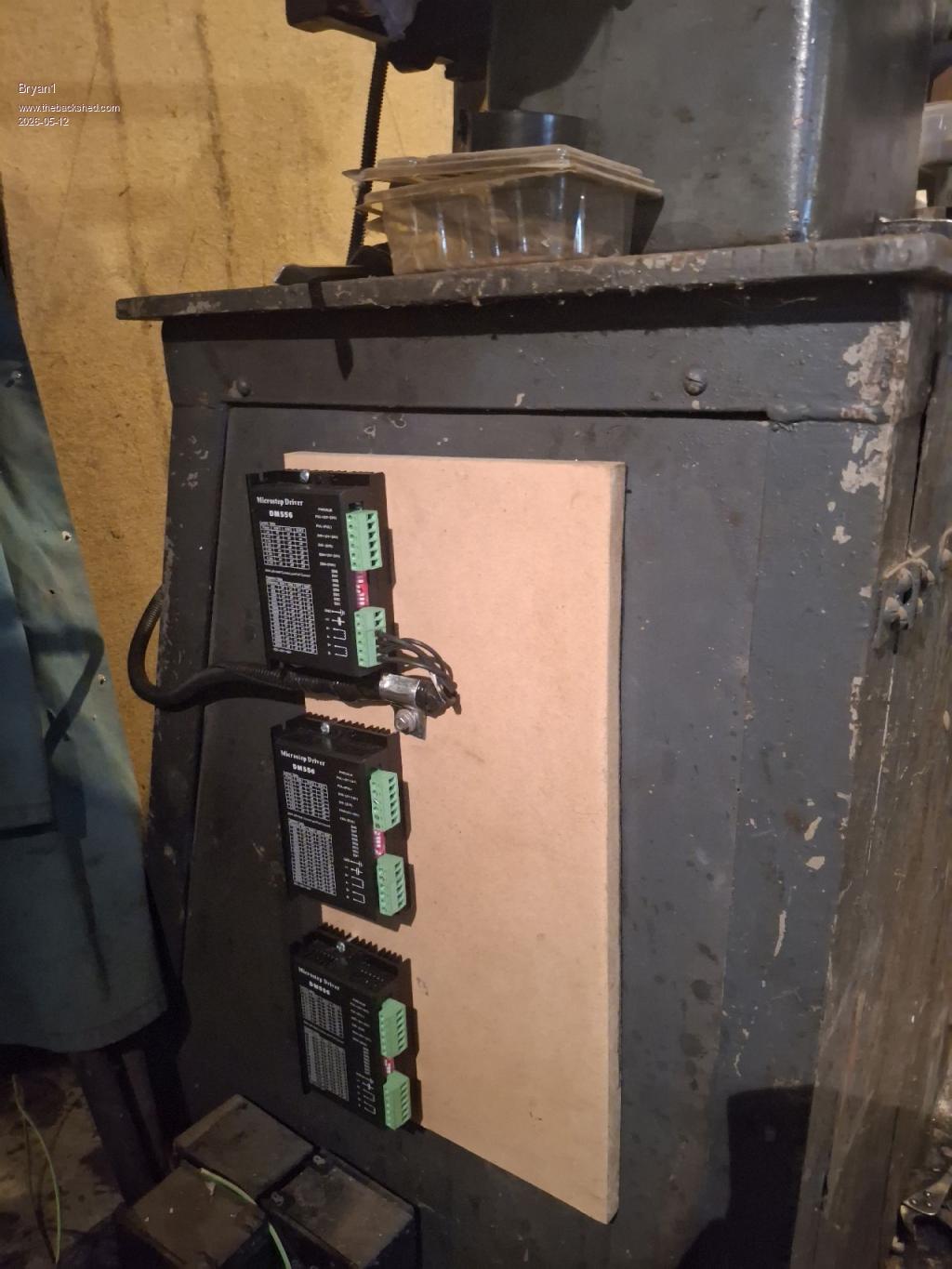 Now with the X axis mount I had to give it a love tap to correct the misalignment on the stepper. Also I made a 4mm spacer to move the mount out for alignment and it worked out a tee. Also this morning got into Sprint Layout where I changed all the drill holes that were still 0.6mm and found the top left 2 transistors didn't respond to the GND test so connected the emitters on C1 to get them working. 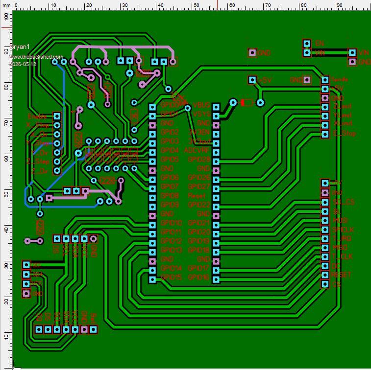 pico 2 board.zip Regards Bryan |
||||
| PhenixRising Guru Joined: 07/11/2023 Location: United KingdomPosts: 1988 |
Hi Bryan, Admittedly, I'm not totally in-sync with the discussions but when you mention "toggle mode", are you referring to manually jogging the axis? Edited 2026-05-12 17:35 by PhenixRising |
||||
| Bryan1 Guru Joined: 22/02/2006 Location: AustraliaPosts: 2136 |
Yes by my term "toggling" it is moving each axis manually, now by lunchtime tomorrow I should be ready to start testing each axis as I do need to get a calibration on the backlash for each axis so when a change in direction is done that backlash amount can be added to the code. Also that 4" LCD should be by this week as got an email from aussie post it's on the way |
||||
| PhenixRising Guru Joined: 07/11/2023 Location: United KingdomPosts: 1988 |
The way I handle jogging is to execute a move to the maximum or minimum allowed position based on Jog+ or Jog- signal. When the Jog signal disappears, execute a stop motion. In my case this can be a decelerate to zero velocity or an immediate stop. I don't see a stop motion command in the stepper reference and so you might need to get creative with small incremental moves while a Jog signal is present. Point being that the commands already exist. |
||||
| PhenixRising Guru Joined: 07/11/2023 Location: United KingdomPosts: 1988 |
That was messing with my 45-degree-diagonals-only OCD  so I had to change them. The bottom VCC track was also bugging me so I had to change them. The bottom VCC track was also bugging me 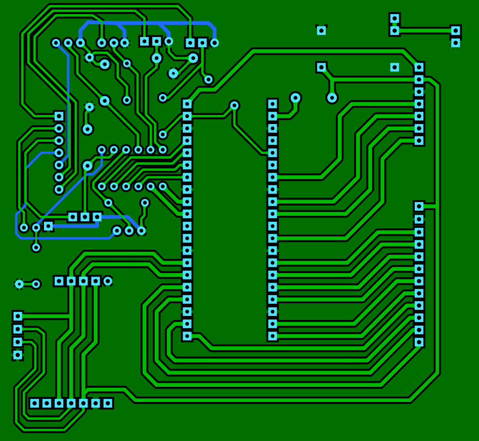 Two pads were not through-hole so I changed them:  pico 2 board.zip Edited 2026-05-13 01:39 by PhenixRising |
||||
| Mixtel90 Guru Joined: 05/10/2019 Location: United KingdomPosts: 8937 |
Ideally, when two traces meet, they should only ever meet at right angles. When sharp points of copper are left between traces there is a tendency to get over-etching, which can cause the board to fail optical testing even if it is fine electrically. It also produces a weak point in the copper. If the two traces differ a lot in width it is good practice for then to meet at a pad, even if it isn't drilled. This re-enforces the junction, once again protecting from over-etching or possible copper lifting with temperature changes. Mick Zilog Inside! nascom.info for Nascom & Gemini Preliminary MMBasic docs & my PCB designs |
||||
| PhenixRising Guru Joined: 07/11/2023 Location: United KingdomPosts: 1988 |
How about this. I put a temporary pad there, generated a "teardrop" and then removed the pad. 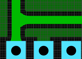 |
||||
| Mixtel90 Guru Joined: 05/10/2019 Location: United KingdomPosts: 8937 |
The "teardrops" and smooth curves are pretty but a) of limited real value and b) a complete pain if you come to edit a board later as they are made from little triangles - they are not part of the trace itself and can be exploded off it. Just don't put bends tighter than 45 degrees in traces, they'll almost certainly be strong enough then, even without curves. They will be easier to guide through narrow spaces too. Mick Zilog Inside! nascom.info for Nascom & Gemini Preliminary MMBasic docs & my PCB designs |
||||
| PhenixRising Guru Joined: 07/11/2023 Location: United KingdomPosts: 1988 |
I dub this "Funky Junction" 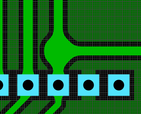 |
||||
| PhenixRising Guru Joined: 07/11/2023 Location: United KingdomPosts: 1988 |
My buddy Gemini: |
||||
| Bryan1 Guru Joined: 22/02/2006 Location: AustraliaPosts: 2136 |
Morning Guy's, Well it does look like this current pcb design does pass the muster with you guy's so I may aswell after a few years have a go with JLCPCB and get the boards made First gotta head into town for more cow juice as I can see quite a few caffines downed today as I play with the code, had a good look this morning and read of the stepper pdf and some of Peter's examples so got a good headwind into the tasks today. Now with the Z axis I still have to set the thrust bearing for the backlash and honestly I can see that shock absorber being fitted as when we need to raise the grinding wheel in a E_Stop condition taking up the backlash isn't an option period, by going this way the grinding wheel doing 2,500 rpm may just survive. On thinking one thing I didn't put on the pcb is the console breakout so that will be the first job to do, then I can use that micro-bridge as the link to teraterm etc. Regards Bryan Edited 2026-05-13 09:00 by Bryan1 |
||||
| Bryan1 Guru Joined: 22/02/2006 Location: AustraliaPosts: 2136 |
Well who ever thought changing over pico's would be so much fun NOT as it was working nicely on with the B board. Now I have setup the 2350A pico and trying to get the LCD working is proving to be the brick wall I'm facing. Now I put the same settings in as the manual as I just needed to reassign T_cs to GP12 and rearrange the CS, RESET and DC pins to suit the manual PicoMite MMBasic RP2350A V6.03.00RC7 OPTION SYSTEM SPI GP18,GP19,GP16 OPTION FLASH SIZE 4194304 OPTION COLOURCODE ON OPTION CPUSPEED (KHz) 200000 OPTION LCDPANEL ILI9488, LANDSCAPE,GP15,GP14,GP13,GP20 OPTION TOUCH GP12,GP17 OPTION SDCARD GP21 > gui test touch Error : Touch not calibrated > > gui calibrate > gui test lcdpanel 39.9666 Circles per Second > So the LCD is not initializing where on power up the screen goes dark/off yet when the USB cable is taken off the back light goes white. I have now reset the DuPont connectors 2 times now and I know they are right. Now it was surprise seeing the GUI test lcdpanel finish but at no time was the lcd showing the circles. |
||||
| Volhout Guru Joined: 05/03/2018 Location: NetherlandsPosts: 5975 |
Hi Bryan, - Try when you pull out the SD card. - Try when you disconnect the TOUCH pins (they are separate pins on the display module). Volhout PicomiteVGA PETSCII ROBOTS |
||||
| Bryan1 Guru Joined: 22/02/2006 Location: AustraliaPosts: 2136 |
OK took the SDCard out and took the T_irq pin lead off and when doing a gui test lcdpanel the backlight is flickering so it does look like the SPI signals were the cause. Now I moved the miso, mosi and clk connections to blank strips and still no change. Now I did do a option reset and when I configured the lcdpanel I used a 1 for the invert option which did show the above condition of the flickering, now without the invert option the lcd just stayed blank/off. Now I have put the same settings as before and they are the same as the manual, now ILI9488 worked before on the B board so not sure why it won't work on the A pico. PicoMite MMBasic RP2350A V6.03.00RC7 OPTION SYSTEM SPI GP18,GP19,GP16 OPTION SYSTEM I2C GP10,GP11 OPTION FLASH SIZE 4194304 OPTION COLOURCODE ON OPTION CPUSPEED (KHz) 200000 OPTION LCDPANEL CONSOLE OPTION DISPLAY 26, 60 OPTION LCDPANEL ILI9488, LANDSCAPE,GP15,GP14,GP13,GP20 OPTION TOUCH GP12,GP17 OPTION SDCARD GP21 Also tried to set the time on the RTC only to get > rtc settime 2026, 05, 13, 16, 18, 0 Error : RTC not responding Now I found on the B board using the 5V pin on the board it powered the LCD fine and found with this A pico 2 I had to put in one of my 5V boards to provide a 5V rail for powering the LCD as the A pico wouldn't power the LCD off the USB power. Edited 2026-05-13 16:53 by Bryan1 |
||||
| Bryan1 Guru Joined: 22/02/2006 Location: AustraliaPosts: 2136 |
Ok finally got the bubbles going now going a gui calibrate froze on the first press so I'm going to call it a day and I do have to say those dupont connectors from jaycar are over priced crap so tomorrow I will rewire the breadboard with CAT5 single strand wire that just works |
||||
| phil99 Guru Joined: 11/02/2018 Location: AustraliaPosts: 3316 |
An ILI9488 requires a diode between LCD_DO and Pico MISO (1N4004 or similar, anode to LCD_DO and cathode to MISO) and a resistor (1k8 to 10k) from LCD_CS to Pico MISO. If the panel has 4k7 pullup resistors on the SD card SPI pins the resistor will need to be 1k8. Presumably your B board has those installed. I have attempted to get that added to the manual without success. |
||||
| Bryan1 Guru Joined: 22/02/2006 Location: AustraliaPosts: 2136 |
Thanks for that Phill I will put those in first thing in morning as I'm rewiring the breadboard with the CAT5 single strand solid wire as those cheap connectors are the main problem. Use them once and the second time expect fun everytime, O'well slowly getting there. Now I am going to setup my 2040 zero as it's on one of Mixtel's boards so breadboard friendly and try and setup I2C so the zero can handle the limits and battery management. As the 2350A doesn't have enough pins to do the 6 limits the zero can handle that task and once I can get it all tested a new pcb will be made so it can include the limit circuit Lyle put on this thread. |
||||
| The Back Shed's forum code is written, and hosted, in Australia. | © JAQ Software 2026 |
