
|
|
Forum Index : Microcontroller and PC projects : MicroMite 44 Pin TQFP Eval PCB/Module
| Author | Message | ||||
TassyJim Guru Joined: 07/08/2011 Location: AustraliaPosts: 6538 |
OK, Here is some code I was working on for a project of my own. I was looking for missing pulses and as set up, it ends the count when there are no pulses for 2000 mS. This suits manual button presses. If you change timeout = 2000 to timeout = 200 it should suit your needs. The code will need changes to fit into the rest of you program but it might be a starting point. ' pulse monitor
timeout = 2000 ' timeout in mS for 6.5Hz try 200mS setpin 21, 6, noteCount ' change this to a suitable interrupt pin pulseTime= TIMER do if value > 0 then ' we have started counting waittime = timer - pulseTime if waittime > timeout then ' timeout time without any pulse print "Final value = ";value value = 0 ' reset the counter ready for the next note endif endif loop end noteCount: pulseTime= TIMER value = value +1 print value ireturn It was run an a Maximite so you will need to change the input pin. Jim VK7JH MMedit |
||||
| viscomjim Guru Joined: 08/01/2014 Location: United StatesPosts: 925 |
Thanks for that Jim. It looks like I was approaching this wrong using a counting pin instead of using an interrupt to count. I will give this a whirl and report back, but in my head it seems to work well. Nice work. I truly appreciate it. |
||||
Grogster Admin Group Joined: 31/12/2012 Location: New ZealandPosts: 9975 |
555 timer, couple of resistors and a cap - will blink an LED with ZERO lines of code!  
(but the 555 is not a MCU, so yes - I am taking the piss a little with this reply!) Smoke makes things work. When the smoke gets out, it stops! |
||||
BobD Guru Joined: 07/12/2011 Location: AustraliaPosts: 935 |
I received a couple of Phil's 44 pin modules a couple of days back. Can someone tell me what the header on the board, circled in green in the image, is used for. 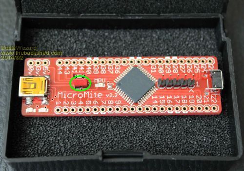 |
||||
| Grogster Admin Group Joined: 31/12/2012 Location: New ZealandPosts: 9975 |
It's the MCU power jumper. Remove this jumper, if you are powering the board from an external 5v supply, using the headers above the USB socket. Basically, it connects the USB 5v supply, to the module, so you can run it from the USB cable. If the module is embedded in something, more then likely you will be feeding it an external power supply, so remove the red jumper in that case. WW does need to include a single sheet of basic info such as what that jumper is for etc, to avoid this kind of confusion... Smoke makes things work. When the smoke gets out, it stops! |
||||
| WhiteWizzard Guru Joined: 05/04/2013 Location: United KingdomPosts: 2991 |
Guys, you are correct about including an instruction sheet with the Module - it is on my long list of action points! Just to make you aware, I am about to launch a website that will have detailed instructions with regards to using the 44-pin MicroMite Module. This should hopefully be available within the week
In the meantime, please note that the board can be used in three different configurations: 1> Basic mode (PIC & caps only - requires 3v3 supply) This is ideal when you want to embed the MicroMite into your own design/PCB 2> Advanced mode (As above but with LDO & reset circuitry) This is for when you have your own usb-to-uart module - requires 5v supply 3> Plug-n-Play mode (as above and includes USB-to-Uart onboard) This is a 'standalone unit' requiring no external power. Ideal for testing a design and experimentation The module in BobD's photo is configured as a 'plug-n-play' module requiring just a USB connection (Note that no headers are soldered as requested by Bob!). With this configuration, the red jumper simply acts as an on/off switch to save the user from having to disconnect the USB lead all the time. Like Grogster says, the jumper can also be used to disconnect USB power so that an external power supply can power the Module. I will make this clear on the website!! Bob - Other than the lack of basic instructions, I do hope your MicroMite Modules are to you liking . . . . 
Regards, Phil |
||||
| BobD Guru Joined: 07/12/2011 Location: AustraliaPosts: 935 |
|
||||
| Grogster Admin Group Joined: 31/12/2012 Location: New ZealandPosts: 9975 |
Happy belated birthday.  Smoke makes things work. When the smoke gets out, it stops! |
||||
| WhiteWizzard Guru Joined: 05/04/2013 Location: United KingdomPosts: 2991 |
that be 10 then!
|
||||
palcal Guru Joined: 12/10/2011 Location: AustraliaPosts: 2039 |
Could be, my Grandson just turned 10 and it's the biggest one he has ever had. I count mine in Hex now makes me feel better. Paul. "It is better to be ignorant and ask a stupid question than to be plain Stupid and not ask at all" |
||||
| WhiteWizzard Guru Joined: 05/04/2013 Location: United KingdomPosts: 2991 |
Hey Paul, that's a great idea - but that makes me '2D'. 
Or put it another way, three years till I'm 30
|
||||
| BobD Guru Joined: 07/12/2011 Location: AustraliaPosts: 935 |
That's a good idea. I'll have to try it. Grogs, it's not yet belated. The date on my profile was early by more than a year. I must have had a brain fade when I did that. I have about 6 weeks to go. |
||||
| BobD Guru Joined: 07/12/2011 Location: AustraliaPosts: 935 |
I've been looking at the Micromite doc for the 44 pin chip and I found the following port assignments. COM1 .... RX=9, TX=8 COM2 .... RX=31, TX=30 I2C ..... SDA=1, SCL=44 SPI ..... Clk=14, DataIn (MISO)=41, DataOut (MOSI)=20 and I know that many of the functions are able to allocate a pin for the event and then release it. Have I missed any? |
||||
| WhiteWizzard Guru Joined: 05/04/2013 Location: United KingdomPosts: 2991 |
Don't know if you want to include the PWM outputs in your list too . . . |
||||
| Frank N. Furter Guru Joined: 28/05/2012 Location: GermanyPosts: 1102 |
Hi Phil, the Royal Mail Track and Trace says since Friday that my parcel "...has arrived in FRANKFURT GERMANY" (I don't live around Frankfurt) but now I received it today and your modules are working very fine! Thanks! Can you offer the actual Eagle file? I think I have only version 1.1 or so... Which one of the files in this thread is the actual schematic? Thanks again! Greetings from Germany! Frank |
||||
| WhiteWizzard Guru Joined: 05/04/2013 Location: United KingdomPosts: 2991 |
Royal Mail's Track&Trace will show you a location of the last sorting office they use to route your package to you. Therefore it would have travelled via Frankfurt so the arrival status is correct. At the top of the status screen if it says 'It's on its way' then the parcel is still in their supply chain. The status will change to 'Delivered' once it arrives at its destination. Please note that the status may not be updated to delivered straight away as it depends on the local postal service and their systems (and how often they update their systems data). I will email you a pdf of the circuit diagram . . . Regards, Phil |
||||
| WhiteWizzard Guru Joined: 05/04/2013 Location: United KingdomPosts: 2991 |
Hi Don & Bob, Don, From what I read, the counterfeit chips only appear to be marked with the 1213-C label. Is that correct OR is it potentially any chip AFTER that date as well? Checking my stock of FTDIs purchased from Mouser (previously purchased from RS Components) the code on the chips that I have are all 1326-C (I am certain this would be what BobD has too - BobD - please confirm!). Also the markings appear to be laser etched rather than printed (implying genuine chips.) Regarding 'buggy' driver, what is your latest understanding of this? Bob, So you are running v2.10 FTDI driver on all three? Were they all installed at near enough the same time? (i.e. while trying to hook up the MicroMite Module the other day) Don, Are you saying v2.10 is the one causing this 'issue' or it is the version that resolves the 'issue'? I will continue to look into this but at least Bob has the ability to use his MicroMite Modules on Windows 8
Gents - Please update me with answers to the above questions! Thanks . . . |
||||
donmck Guru Joined: 09/06/2011 Location: AustraliaPosts: 1314 |
All of the tests I have done are with molded cables, that is, USB to 6 pin TTL in the usual FTDI fashion. See: http://www.dontronics-shop.com/ftdi-usb-to-serial-ttl-level- 33v-converter-cable.html So I have no way of knowing what the chip batch number is unless I destroy the cable. Regarding versions, please read the start of: http://www.dontronics-shop.com/usb-communication-problem-ftd i-ft232r-1213-c-bug-and-workaround.html The current version will kill the cables that are either buggy or counterfeit. Mind you, I have no proof of counterfeit chips, but I have asked FTDI engineering about this possibility, but received no response to date. I am suspecting that the Chinese will readily copy anything if there is 25 cents in it for them. (Was a buck, but global prices have changed dramatically) Cheers Don... https://www.dontronics.com |
||||
| BobD Guru Joined: 07/12/2011 Location: AustraliaPosts: 935 |
The chips that I have are marked 1326-C which I presume is a manufacturing date of year 2013 and week 26. I have 3 partitions on one machine. All of the testing was done on the one physical USB socket. win 8.1 64 bit - FTDI driver v2.08.14 force installed and working OK, V2.10 will not install under any method. win 8.1 64 bit - FTDI driver V2.10 automatically installed by Win and working OK win 8.1 32 bit - FTDI driver V2.10 automatically installed by Win and working OK I am of the opinion that the failure here is due to Windows. The two systems that work with V2.10 have minimal software installed. The one that does not work with v2.10 has a fair bit of software installed. Coincidence? |
||||
| donmck Guru Joined: 09/06/2011 Location: AustraliaPosts: 1314 |
For that one, can you remove the driver as per the instructions on my page, and force install the latest exe driver from: http://www.ftdichip.com/Drivers/VCP.htm which should be: http://www.ftdichip.com/Drivers/CDM/CDM%20v2.08.30%20WHQL%20 Certified%20for%20Windows%208.1.exe Cheers Don... https://www.dontronics.com |
||||
| The Back Shed's forum code is written, and hosted, in Australia. | © JAQ Software 2026 |
