
|
|
Forum Index : Microcontroller and PC projects : Micromite EVEN MORE eXtreme
| Author | Message | ||||
Grogster Admin Group Joined: 31/12/2012 Location: New ZealandPosts: 9975 |
@ panky - I 2nd that.  Smoke makes things work. When the smoke gets out, it stops! |
||||
bigmik Guru Joined: 20/06/2011 Location: AustraliaPosts: 2981 |
WW, ALL, No Problem, I cant wait to get my hands on one of these boards.. Great job from All involved.. Kind Regards, Mick Mick's uMite Stuff can be found >>> HERE (Kindly hosted by Dontronics) <<< |
||||
| cdeagle Senior Member Joined: 22/06/2014 Location: United StatesPosts: 269 |
I always appreciate the unselfish effort of others. Their work makes it easier for the rest of us and demonstrates the deductive nature of building hardware and writing software. "If I have seen further it is by standing on the sholders [sic] of Giants." Isaac Newton "I never worry about the future. It will be here soon enough." Albert Einstein |
||||
| WhiteWizzard Guru Joined: 05/04/2013 Location: United KingdomPosts: 2991 |
Time for an UPDATE: PCBs have started shipping as of yesterday (Friday 3rd February)  More PCBs going out today, and all pre-orders should be despatched by end of next week. This PCB is the second version; and although Peter and myself spent many hours studying it, there were a couple of 'minor' things that crept through (I like to call them minor anyway!) So please note the following SilkScreen/Solder-resist issues: PWM Header: This is the important one! The 3v3 and 5v legends are the wrong way round. So on this version of the PCB, you can safely plug your 3v3 PWM devices into the 5v output  DO NOT PLUG 3v3 PWM DEVICES INTO THE 3v3 OUTPUT!  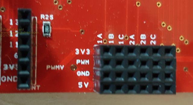 Peter has already fixed this for the next revision PCB ICSP: The ICSP Pin 1 is the 'bottom' pin. The Silkscreen legend is slightly higher than it should be 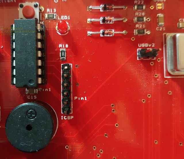 NunChuck Connector A NunChuck can be directly inserted into the MMX144 PCB to allow software control of the mouse pointer (and many other menu driven type functionality - as well as a 3-axis accelerometer). However, the NunChuck could be inserted either way around - so beware as you have a 50% chance of getting it wrong and possibly damaging the NunChuck itself! In most commercial products that utilise a NunChuck, the product's case provides a key-cut-out to ensure correct orientation of the NunChuck. However, the MMX PCB is not cased (yet!). So please refer to the following photos to help ensure correct usage: The NunChuck connector has the solder resist still over the four required connections (two top, two bottom): 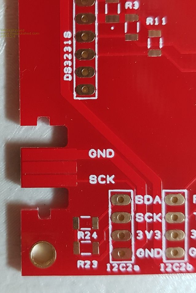 I simply scraped the solder-resist away (using a knife blade) on the four 'outer' pads; and then run a bed of solder over the exposed gold contact: 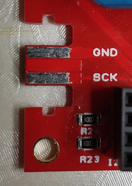 For those of you with really sharp eyes, I also had to increase the gaps on this connector by filing about 0.5mm off both top and bottom edges (i.e. the ones with the 'notch cut-outs') NunChuck Pin-out (that matches PCB silkscreen legends): 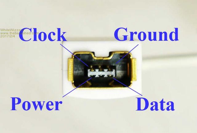 And in real life: 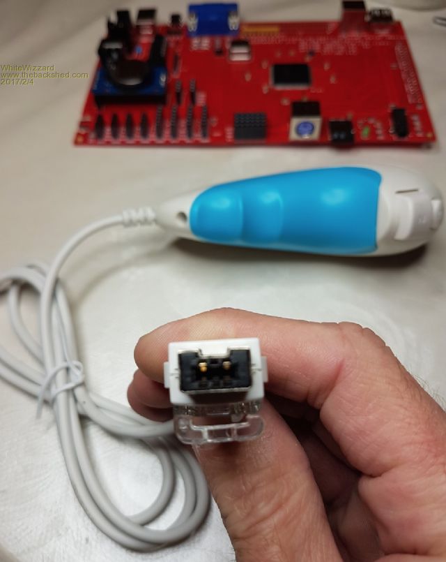 NOTE: On Genuine NunChuck's, and on 'most' clones, there is a big 'lump of plastic' This can also aide orientation in addition to the 'U-shape' key on the metal part: 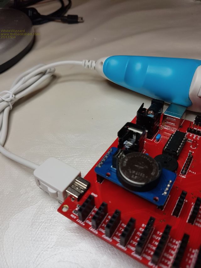 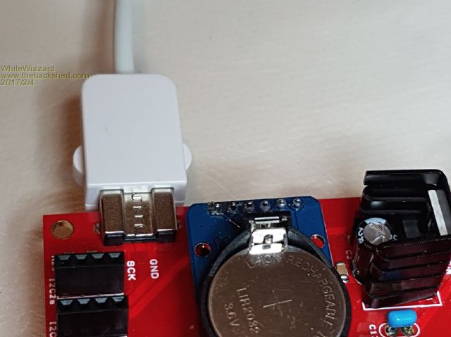 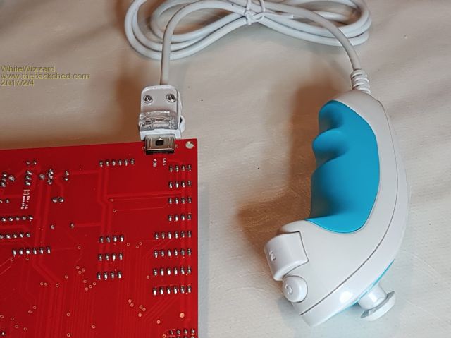 RTC: The orientation of the RTC is the opposite to those of you that are using the Explore 100 - so beware! I like to add pins to the RTC; so for the MMX144 they need to be like this: 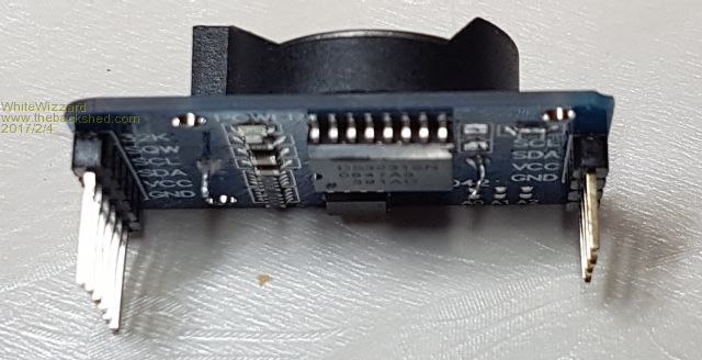 And when mounted: 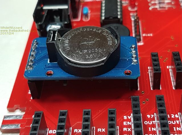 Thats all for now folks. Hope the above is clear enough to follow. Now back to assembling your pre-orders . . . . . WW |
||||
| matherp Guru Joined: 11/12/2012 Location: United KingdomPosts: 11513 |
If you have a "cheap" clone Nunchuck then you may find it fits without filing - mine certainly does. I found using a fibre glass pen pen was the easiest way of safely removing the solder resist. Very annoying getting the 5V and 3.3V legends the wrong way round. The idea is that the "real" 5V, PWM, GND are arranged so that you can plug a standard servo directly onto the board and it will be powered by the 5V rail Also, there are at least two variants of the RTC modules and they have very slightly different spacing between the two sets of pins. The PCB is an exact fit for one variant (the one I measured). The other will fit OK in a pair of sockets but not solder direct to the board. |
||||
| WhiteWizzard Guru Joined: 05/04/2013 Location: United KingdomPosts: 2991 |
I did file your PCB before I sent it  |
||||
| panky Guru Joined: 02/10/2012 Location: AustraliaPosts: 1127 |
@WW Phil, No info on your website yet on the MMX144? Would like to get hold of the final schematic plus some hi-res pics of a bare board - when assembled with a 7" display attached, all that nice on PCB info on pinouts no longer acessable. Also, it would be a nice addendum to Peter's manual to include all the 144 PCB assembly notes. Other than that, all working fine - just can't keep up with trying Peter's enhancements Regards, Doug. ... almost all of the Maximites, the MicromMites, the MM Extremes, the ArmMites, the PicoMite and loving it! |
||||
| matherp Guru Joined: 11/12/2012 Location: United KingdomPosts: 11513 |
If anyone fancies typing up I'll include in the manual 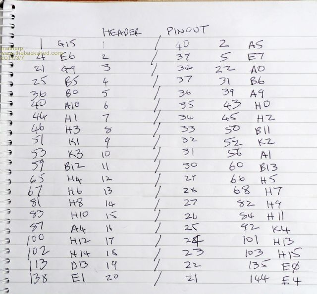 |
||||
| WhiteWizzard Guru Joined: 05/04/2013 Location: United KingdomPosts: 2991 |
Peter, I will knock up a quick diagram and send it across later this morning WW |
||||
| WhiteWizzard Guru Joined: 05/04/2013 Location: United KingdomPosts: 2991 |
Especially for Panky . . . . Peter will add to next version of MMX manual (he has probably done so already!) 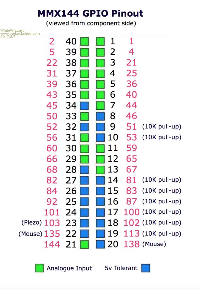 |
||||
| CaptainBoing Guru Joined: 07/09/2016 Location: United KingdomPosts: 2171 |
are those "has 10K pullup" or "requires 10K pullup" (i.e. open drain) ? |
||||
| WhiteWizzard Guru Joined: 05/04/2013 Location: United KingdomPosts: 2991 |
There is provision for a 10K SIL Resistor package (R2) to be mounted on the MMX (close the the GPIO connector). I have installed it on all the MMX144 modules so therefore the meaning is 'has a 10K pull-up'. I will let Peter confirm if they are open collector or not as I don't want to mislead anyone. (I believe all pins shown in blue are Open Collector as they are 5v tolerant on a 3v3 operated PIC - no doubt someone will clarify shortly!) WW |
||||
| isochronic Guru Joined: 21/01/2012 Location: AustraliaPosts: 689 |
BTW the micromite.org domain implies a non-commercial site ? For a UK based private business the domain should probably legally be more like micromite.co.uk I think ? |
||||
| WhiteWizzard Guru Joined: 05/04/2013 Location: United KingdomPosts: 2991 |
Let me clarify for you Stu. From 1985 until 2003 .org websites were indeed intended for non-profit organisations. However since 2003, this restriction was lifted and they can now be used by anyone - even by commercial organisations; profit or otherwise. I set up MicroMite.org in early 2014 for helping TBS members to get hold of various MicroMite hardware 'goodies' and thanks to the support of many loyal members/customers it has grown in popularity. I have purchased .co.uk and .net along with some others and trialled various 'hits' and .org returned the most which is why I stuck with that one. Subsequently some domains I did not renew (.co.uk), and others I kept. I could not get .com as it was with another totally non-linked company. And if you could define profit please! If you ignore my time, then I barely break-even. Take into account my time, and I make a commercial loss. One thing I am committed to is spreading the word about the MicroMite; and also pushing forward its capabilities and making things available through the website. Before you ask, this is with Geoff's full permission, along with Peter's excellent support. I will continue to dedicate my time to the MicroMite, and hope that others here find at least some small benefit from the tireless hours I spend stress-testing, soldering, proof-reading, advising, helping, phoning people directly, designing, and buying stock from other members. If I have only helped one person, then I am happy WW.org Facts about .org |
||||
| CaptainBoing Guru Joined: 07/09/2016 Location: United KingdomPosts: 2171 |
I have been playing with PICs since the 1990s. Forest Electrical Developments provided a Basic compiler to my then employer but I always preferred assembler, coming from a 8080/Z80/68000/8086 background with heavy emphasis on interfacing CPUs to the real world. it was through MicroMite.org that I first discovered the whole microMite "scene" and I'm sad to say that I had never heard of the projects in Silicon Chip that Geoff had been involved in. I was a very late-comer having done (and still do) a lot of my stuff with PIC assembler or Great Cow Basic for smaller project that require the flexibility of built in commands (string slicing in PIC asm is a pain in the neck!) - it was a world of wonder opened up - like finding microcontroller gold! All that mucking about with floating point modules in PIC assembler has almost completely gone. All that power in a 28pin chip and no Xtal required! just VCC and a capacitor and off you go. I still have to pinch myself. Larger projects get a MM now-a-days purely for the ease of development, smaller things get GCB with a LOT of assembler. My hand in the air - thanks. What would I change? GeoffG and Pete Mather have a "Donate" button on their websites!!! |
||||
| The Back Shed's forum code is written, and hosted, in Australia. | © JAQ Software 2026 |
