
|
|
Forum Index : Electronics : Various aspects of home brew inverters
| Author | Message | ||||
| poida Guru Joined: 02/02/2017 Location: AustraliaPosts: 1480 |
Part 10: sizing the inverter for my particular requirements and efficiency concerns Given: - the cost of power is only going to increase, and faster than CPI - zero political desire or capability to reduce these cost increases - gas is also only going to go up in price, faster than CPI for the same reasons. - I live in Melbourne, this means lots of cloudy skies - (this may be very controversial) we are headed for the mother of all economic depressions when the house market collapses, taking banks, personal savings, jobs, etc with it - I have some savings in one of the big 4 banks I thought - make a solar power system. - go for the easy 75% of value return, not 100% which would get costly. - accept I will never supply 100% in Melbourne. About 30kW array needed plus a huge battery. - get a ROI at 10-15 years. - slowly transition to a house using less high power things. We use electric cooktop, microwave, clothes iron, kettle. This can be reduced as items need replacement. - get some money out of the bank so I don't loose it when we all �bail-in� the banks. So I have a 3kW solar array, feeding a 400Ah 48V battery. All data is logged to non-volatile storage every 2 minutes. I have 1 1/2 years of data showing street power and inverter supplied power consumed by my house. Looking at it gives me clear guidance in inverter sizing. First, see the total energy consumed by the house from Jan 2016 to date, there are two lines here. Note my solar system can supply nearly 1/2 house needs. But when Winter comes, forget about it. Not even close. But with 4.5MwHr self supplied, I can say this has returned me 4,500 x $0.29/kWhr (my rate) or $1,300 for this hybrid system. 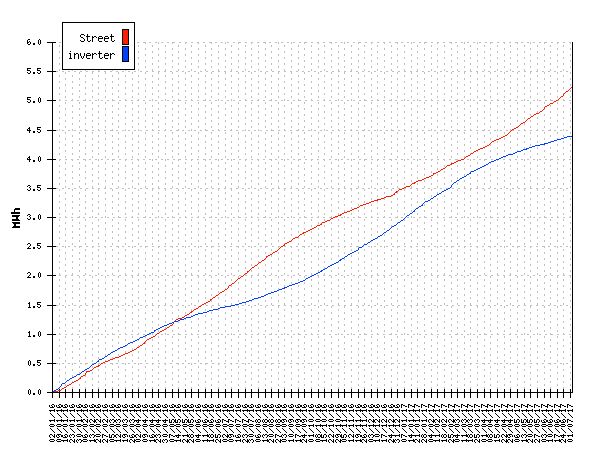 Let�s have a look at the average power consumption level at any time in the 24 hr day. It shows me that I need 1500W on average peak power, around 19:00 or 7pm which is when we cook. That is why the peak is at that time. We have a tropical fish tank too. Hence the high night time power levels. The house spends a lot of time less than 1000W. I like to imagine how it would look if we installed a gas cooktop and oven and gave the fish away. This is about 18kWhr/day average house consumption. 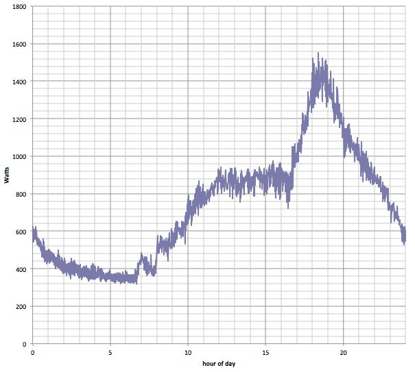 Now, here is the total time (in 2 minute slices, added together) the inverter has spent at various power levels. The inverter is a Victron 3000VA inverter/charger. 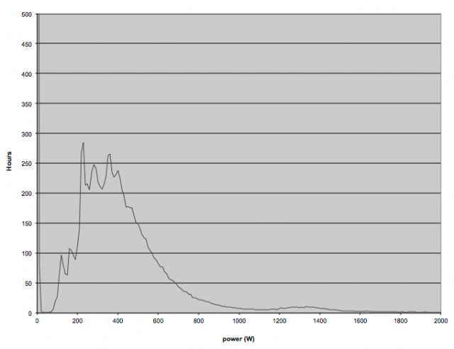 It is clear to me that I need to build a replacement inverter that is optimised for power levels up to 700W because it spends more than 90% of it�s time running at these levels. Finally here is the cumulative energy total, as you totalise the different inverter power outputs. The small time spent at 1000W and more needs to be carefully designed so as to not kill the total efficiency equation. If the about 500kWhr made at 1500W levels is at an efficiency of 85% only, then that is 75kWh loss. The 3000kWhr made at 93% (which I am demonstrating right now on my bench) means I lose 210 kWh while operating in that regime. So it�s 1/4 lost at high levels and 3/4 lost at low levels of inverter output. 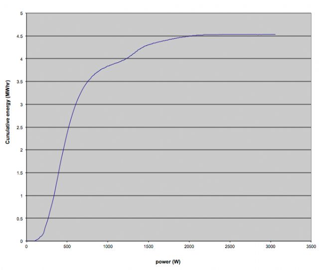 Consequentially I am designing a replacement for the Victron that is 93% at 700W but can handle peaks in excess of 3000VA. I'm currently obsessed by mosfet switching and cross conduction. This is where I can find further efficiency gains. A post on this subject will come when it is ready. wronger than a phone book full of wrong phone numbers |
||||
Madness Guru Joined: 08/10/2011 Location: AustraliaPosts: 2498 |
ATM I have the grid available but mainly run off my off grid system. What I have found that you did not mention is that Offgrid is more reliable than the grid. Such as what happened in SA a little while ago and when ex-cyclone Debbie went through our area our lights were still on but all the neighbours were in the dark for nearly 3 days. If you are worried about the banks and the financial world collapsing you may be better off buying gold. There are only 10 types of people in the world: those who understand binary, and those who don't. |
||||
| Warpspeed Guru Joined: 09/08/2007 Location: AustraliaPosts: 4406 |
Agree the economic future does not look bright, but personal circumstances can vary a great deal, age, career and marital status, children, mortgage, and so on. Its not just the inevitable financial and social collapse, but the possibility of nuclear war is also rapidly increasing. Anything we can do to become more self sufficient and less dependent on "the system" may help to isolate us somewhat. I am living in suburban Melbourne and hope to become completely grid free over the next twelve months or less. Doing it in stages, and am gathering data and learning as I go. First stage currently working now, is to use solar to supplement rectified dc grid power to drive an inverter (without a battery). Its not a conventional grid tie system, it feeds nothing back. At the moment we are right at the winter solstice, but still am getting about 55% from solar even on totally miserably cloudy days. That rises to about 80% at the summer solstice. I have sufficient solar input to cover all my daily consumption over about a seven hour period even on the worst solar days. Night time grid consumption over seventeen hours is only about 45% of my total. Stage two will involve a completely different system that uses a high voltage Lithium battery (100v nominal, from thirty Winston cells) which should see me totally off grid. I will then have two different systems available, new system and the old system as reserve. So if something blows up or requires maintenance I can do it without going back to 100% grid power. System three is planned for some time into the future, but the way to get very high system efficiency is to first use a higher voltage battery, and build an inverter that does not require the use of a large toroidal output transformer. An output transformer greatly increases the zero load idling power, no matter how you go about it, and limits the maximum peak output power. A much better way would be to directly PWM the battery voltage to create an ac voltage directly, that can be used without requiring a transformer. This will greatly increase the efficiency at very low output load and allow massive peak power demand with good voltage regulation. There are definite safety issues with this, but a 100v battery is still practical if treated with the utmost respect. A +100v battery and a -100v battery would not be any more dangerous than a single 100v battery, but supplies 200v between the battery rails. If we PWM that with a half bridge switcher we can get up to 140 volts rms output directly, referenced to zero volt ground. Two PWM outputs operating out of phase would provide two voltage regulated 120v outputs, or 240v between. Something like the US power distribution system. The efficiency would be very high, especially at very low loads, and high dc voltage means low current everywhere in the system. That is what I eventually hope to have. I also agree that Gold or Silver is a pretty safe store of value, has been throughout all of recorded history, and still is. Cheers, �Tony. |
||||
| Warpspeed Guru Joined: 09/08/2007 Location: AustraliaPosts: 4406 |
Double post removed. Cheers, �Tony. |
||||
| poida Guru Joined: 02/02/2017 Location: AustraliaPosts: 1480 |
Part 11: how does the PWM thing work? Just the basic idea.. These inverters we are making and exploring take a DC power source and convert it into an AC output, fed into the primary winding of a transformer. See the below circuit, taken from Tinker's post 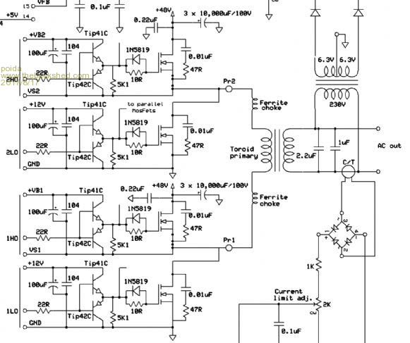 I see the circuit as having 4 switches, named 1LO, 1HO, 2LO and 2HO When using the EG8010 or EGS002 parts, 1LO and 1HO drive the 50Hz output and 2LO, 2HO drive the 20Khz PWM output. It's important for my understanding to choose a reference point for all measurements. I choose DC ground. IF you put a oscilloscope probe on Pr1 with the probe grounded to DC supply ground you will see a 50Hz square wave - nearly all the signal will consist of 50Hz square wave, the low 1/2 cycle being close to ground volts and the high 1/2 cycle close to DC bus supply volts. Put another probe on Pr2 (also this signal is relative to DC supply ground) This will have a 20KHz square wave running with differing duty cycles depending on where in the 1/2 50Hz cycle you are looking. (the high frequency PWM signal is a 20KHz square wave with positive duty cycle percentage times varying from sin(0) to sin(90 deg) then back to zero. The inverter power output is controlled by a factor that is multiplied to the sin(). Typically my inverter runs at 70% modulation with zero loads. The modulation factor starts at zero at the start of the 3 second soft-start then it increases during the 3 seconds to some value that results in the desired AC voltage output as seen by the feedback network) At steady state running, with the inverter producing it's expected AC output voltage you will see again a signal at Pr2 that exists primarily at only two values, ground and DC supply. With a DSO (digital storage oscilloscope) you can quite easily capture portions of the PWM generated for the gate drives. The transformer primary winding sees the voltage difference between Pr1 and Pr2. We can easily see what this difference looks like with the oscilloscope (my DSO has a simulated low pass filter I can apply to a signal and I can perform math functions on 2 signals.) See the following DSO captures Yellow is the voltage at Pr1 Light Blue is that at Pr2 after passing through a low pass filter. Purple is (Pr1 - Pr2) i.e. what the transformer gets. First is where there is zero modulation of the SPWM, leaving the difference = nearly zero. The primary winding sees differing absolute voltages, changing each 1/2 cycle of the 50 Hz but it sees nearly zero difference in the two signals. 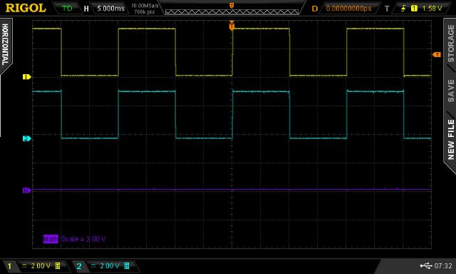 Next I modulate the SPWM to about 10% max, and we see a small sine wave appear on the purple trace. Subsequent images show increasing modulation of the SPWM. 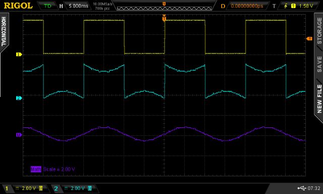 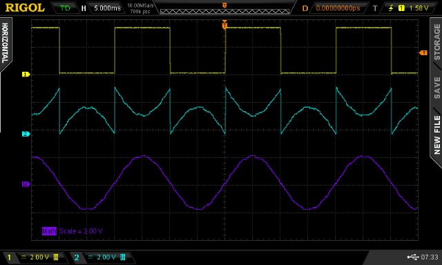 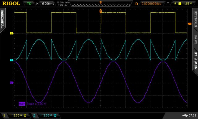 Notice the shape of the high frequency PWM signal (Pr2). See how within one of the 50Hz 1/2 cycles it appears as a 1/2 of a sine wave? This makes sense since the primary winding sees the result of (Pr1 - Pr2) which is a sine wave portion going from zero to negative DC bus and back to zero. The other half of the cycle is a bit strange. Pr1 = Yellow and is at DC bus voltage. The SPWM is in fact (1 - sin) and so Pr2 starts out at DC bus voltage, reducing down to zero and returning to DC bus. The primary winding sees the difference of this which is (Pr1 - Pr2) and so thats the positive sine wave half we see in purple. This is how we can apply an alternating current (going from +DCbus x modulation% to -DCbus x modulation %) to the primary winding. This can easily be done by anyone with a reasonable oscilloscope and an Arduino I used in this case an Arduino Due (I'm playing with dead-time concepts at the moment) 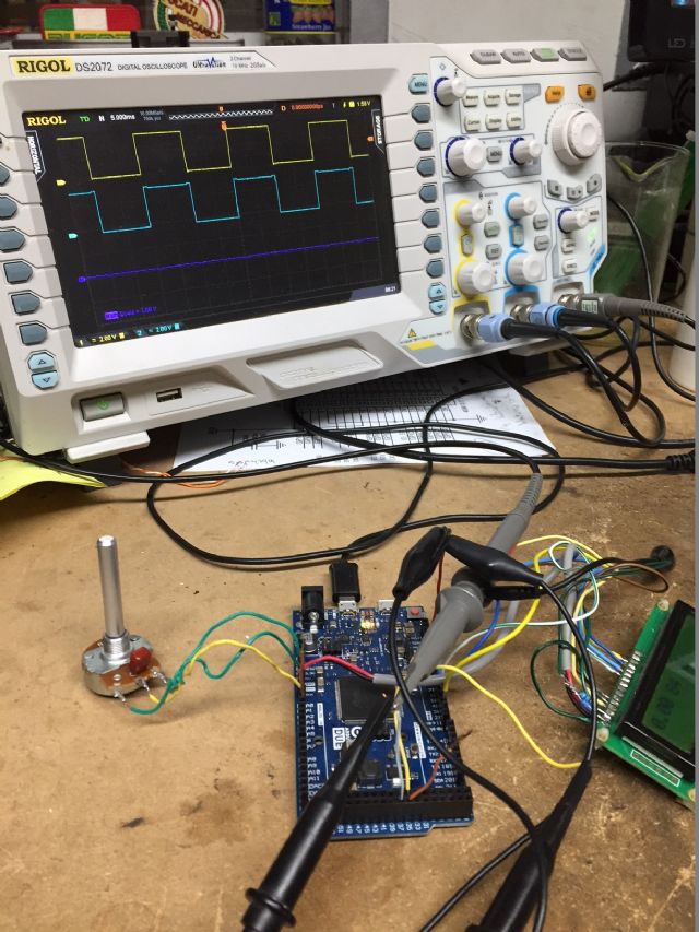 Here is the code. Attach a potentiometer to A0 to be able to control the modulation % It includes my very good Bessel 4 pole low pass filter code, which is not used right now. // include the library code #include <LiquidCrystal.h> // initialize the library with the numbers of the interface pins LiquidCrystal lcd(12, 11, 5, 4, 3, 2); uint32_t *rp; const float bessel4[][11] = // Fc,gain,a0,a1,a2,a3 { {0.0053200, 2635991.5606778641, -0.8537384202 , 3.5510024223 , -5.5404118329 , 3.8431417609 }, {0.0061180, 1524781.5028650849, -0.8337254066 , 3.4878631969 , -5.4739836959 , 3.8198354122 }, {0.0070358, 883513.1860838116, -0.8112892283 , 3.4165503092 , -5.3983852107 , 3.7931060203 }, {0.0080911, 512939.7368203878, -0.7862322979 , 3.3362255664 , -5.3124886713 , 3.7624642100 }, {0.0093048, 298461.1977263077, -0.7583710038 , 3.2460350374 , -5.2150728656 , 3.7273552237 }, {0.0107005, 174105.9270733614, -0.7275473263 , 3.1451347330 , -5.1048310546 , 3.6871517498 }, {0.0123056, 101858.4380555421, -0.6936434579 , 3.0327261291 , -4.9803864405 , 3.6411466885 }, {0.0141514, 59787.5833156785, -0.6565993513 , 2.9081027536 , -4.8403169120 , 3.5885458956 }, {0.0162741, 35224.8633726978, -0.6164331532 , 2.7707099615 , -4.6831925330 , 3.5284615001 }, {0.0187152, 20841.4645647156, -0.5732637347 , 2.6202185372 , -4.5076286708 , 3.4599061679 }, {0.0215225, 12390.4781106740, -0.5273341360 , 2.4566125746 , -4.3123589872 , 3.3817892345 } }; const uint16_t si[201] = { 0, 129, 257, 386, 515, 643, 772, 900, 1029, 1157, 1285, 1414, 1542, 1670, 1798, 1926, 2053, 2181, 2309, 2436, 2563, 2690, 2817, 2944, 3070, 3196, 3322, 3448, 3574, 3700, 3825, 3950, 4075, 4199, 4323, 4447, 4571, 4694, 4818, 4940, 5063, 5185, 5307, 5429, 5550, 5671, 5791, 5912, 6031, 6151, 6270, 6389, 6507, 6625, 6742, 6859, 6976, 7092, 7208, 7323, 7438, 7553, 7667, 7780, 7893, 8006, 8118, 8229, 8340, 8451, 8561, 8670, 8779, 8887, 8995, 9102, 9209, 9315, 9421, 9526, 9630, 9734, 9837, 9940, 10042, 10143, 10244, 10344, 10444, 10542, 10641, 10738, 10835, 10931, 11027, 11121, 11216, 11309, 11402, 11494, 11585, 11676, 11766, 11855, 11943, 12031, 12118, 12204, 12290, 12375, 12458, 12542, 12624, 12706, 12787, 12867, 12946, 13024, 13102, 13179, 13255, 13330, 13405, 13478, 13551, 13623, 13694, 13764, 13833, 13902, 13970, 14036, 14102, 14167, 14232, 14295, 14357, 14419, 14480, 14539, 14598, 14656, 14713, 14769, 14825, 14879, 14932, 14985, 15036, 15087, 15137, 15186, 15233, 15280, 15326, 15371, 15415, 15458, 15501, 15542, 15582, 15621, 15660, 15697, 15733, 15769, 15803, 15837, 15869, 15901, 15931, 15961, 15989, 16017, 16044, 16069, 16094, 16117, 16140, 16162, 16182, 16202, 16221, 16238, 16255, 16270, 16285, 16299, 16311, 16323, 16333, 16343, 16352, 16359, 16366, 16371, 16376, 16379, 16382, 16383, 16384}; #define NPWM 200 #define PPWM (840000 / (NPWM)) int spa_count,spb[NPWM*2+2],*sp,uf,psc; int maxpwm,v; float a0,a1,a2,b1,b2,z1,z2; int u2,u3; long pt; float xv[10],yv[10]; int fc_b4; float gain,a3; void setup() { uint32_t *t; int i; pwm_mod(PPWM); spa_count=0; sp = spb; uf=0; pwmc_setup(); REG_PWM_CDTY1 = 26250; ADC->ADC_MR |= 0x80; //set free running mode on ADC ADC->ADC_CHER = 0xc0+1; //enable ADC on pin A0,A1 and a7 z1=z2=0.0; /* volatile unsigned int* SysTickControl = (unsigned int*) 0xE000E010; *SysTickControl = 0; // disable arduino timer, used by millis() etc. */ lcd.begin(16, 2); // preload Bessel filter coeffs, indexing into above table of values of varying F(cut-off) i = 10; gain = bessel4[1]; a0 = bessel4[2]; a1 = bessel4[3]; a2 = bessel4[4]; a3 = bessel4[5]; } void pwm_mod(long v) { int i; for(i=0; i < NPWM/2; i++) spb= spb[NPWM-i] = (si[(i * 200) /(NPWM/2)] * v) >> 14; spb[NPWM/2] = spb[NPWM/2 + 1] = spb[NPWM/2 - 1]; for(i=0; i < NPWM; i++) spb[i+NPWM]=PPWM - spb; } void loop() { // work out error, increase or decrease spb[] accordingly // read analog input, scale and get delta from setpoint, use a bit of PID to drive correction factor // impliment the soft start, disable/enable output (only during 50Hz zero crossing) // likely that this code will get interrupted by one or both of the PWM and so we have a situation where // this code is writing to data that the interrupt routine will be reading. // //REG_PIOD_ODSR = 2; REG_PIOD_ODSR = 0; // toggle pin 25 // // float r,s,t,f; int j,k, u; if(uf==0) return; uf=0; // sample A0, using direct register access // NO NEED TO CHECK IF ADC result is ready, just read it. // while((ADC->ADC_ISR & 0x80)==0); j = ADC->ADC_CDR[7]; // direct ADC conversion read A0 u = ADC->ADC_CDR[6]; // and A1, not used here s = (float)j / 4087.0; /* // 4 pole Bessel LP filter PWM input via noisy potentiometer on A0 line xv[0] = xv[1]; xv[1] = xv[2]; xv[2] = xv[3]; xv[3] = xv[4]; xv[4] = s / gain; yv[0] = yv[1]; yv[1] = yv[2]; yv[2] = yv[3]; yv[3] = yv[4]; yv[4] = (xv[0] + xv[4]) + 4 * (xv[1] + xv[3]) + 6 * xv[2] + ( a0 * yv[0]) + ( a1 * yv[1]) + ( a2 * yv[2]) + ( a3 * yv[3]); s = yv[4]; */ if (s > 0.999) s = 0.999; if (s < 0.001) s = 0.001; v = (int)(s * PPWM); REG_PIOD_ODSR = 2; pwm_mod(v); REG_PIOD_ODSR = 0; u = 84; // dead time, in uC clocks. arduino due has a 84MHz clock REG_PWM_DTUPD0 = (u << 16)+u; //can change this on the fly if wanted. lcd.setCursor(0,0); lcd.print(s); lcd.print(" "); lcd.print(u); lcd.print(" "); lcd.print(u3); lcd.print(" "); } void pwmc_setup() { //Configure PWM channels 0,1 REG_PIOC_PDR = 0x3FC; //B1111111100, PIO Disable Register REG_PIOC_ABSR = REG_PIOC_ABSR | 0x3FCu; //B1111111100, Peripheral AB Select Register pmc_enable_periph_clk(ID_PWM); REG_PWM_ENA = REG_PWM_SR | 0x000003; //PWM Enable Register | PWM Status Register (activate channels 0,1), was B11111 ie all 5 low REG_PWM_CMR0 = 0x10000; //Channe0 Mode Register: Dead Time Enable DTE=1, clock divider = 0, use Mclk REG_PWM_CMR1 = 0x10005; //Channe1 Mode Register: Dead Time Enable DTE=1, clock divider = 5, use Mclk/512 REG_PWM_DT0 = 0x2a002a; //Channe0 Dead Time Register REG_PWM_DT1 = 0x020002; //Channe1 Dead Time Register REG_PWM_CPRD0 = PPWM; //Channe0 Period Register 20 kHz REG_PWM_CPRD1 = 52500; //Channe1 Period Register 50 Hz NVIC_DisableIRQ(PWM_IRQn); // set up interrupt NVIC_ClearPendingIRQ(PWM_IRQn); NVIC_SetPriority(PWM_IRQn, 0); NVIC_EnableIRQ((IRQn_Type)36); //NVIC_EnableIRQ(PWM_IRQn); PWM_INTERFACE->PWM_IER1 = 0x0003; //enable interrupt on channel 0 PWM_INTERFACE->PWM_IDR1 = 0x00FF00fc; //enable interrupt on channel 0 // enable 16 pins in port D REG_PIOD_PER = 0x00ff; REG_PIOD_OER = 0x00ff; REG_PIOD_OWER = 0xFFFF; } void PWM_Handler(void) // PWM interrupt handler { uint32_t ir1; ir1 = PWM_INTERFACE->PWM_ISR1; // clear interrupt flag if ((ir1 & 2) == 2) { // runs after each cycle of 50Hz // spa_count=0; sp = spb + 1; uf=1; pt=0; psc=0; } if ((ir1 & 1) == 1) { // runs after each pwm cycle, 20 kHz REG_PWM_CDTYUPD0 = *sp; psc++; sp++; } } Here is Arduino Uno code for the same thing #define cbi(sfr, bit) (_SFR_BYTE(sfr) &= ~_BV(bit)) #define sbi(sfr, bit) (_SFR_BYTE(sfr) |= _BV(bit)) #define NPWM 200 #define PPWM (160000 / NPWM) const uint16_t PROGMEM si[201] = { 0, 129, 257, 386, 515, 643, 772, 900, 1029, 1157, 1285, 1414, 1542, 1670, 1798, 1926, 2053, 2181, 2309, 2436, 2563, 2690, 2817, 2944, 3070, 3196, 3322, 3448, 3574, 3700, 3825, 3950, 4075, 4199, 4323, 4447, 4571, 4694, 4818, 4940, 5063, 5185, 5307, 5429, 5550, 5671, 5791, 5912, 6031, 6151, 6270, 6389, 6507, 6625, 6742, 6859, 6976, 7092, 7208, 7323, 7438, 7553, 7667, 7780, 7893, 8006, 8118, 8229, 8340, 8451, 8561, 8670, 8779, 8887, 8995, 9102, 9209, 9315, 9421, 9526, 9630, 9734, 9837, 9940, 10042, 10143, 10244, 10344, 10444, 10542, 10641, 10738, 10835, 10931, 11027, 11121, 11216, 11309, 11402, 11494, 11585, 11676, 11766, 11855, 11943, 12031, 12118, 12204, 12290, 12375, 12458, 12542, 12624, 12706, 12787, 12867, 12946, 13024, 13102, 13179, 13255, 13330, 13405, 13478, 13551, 13623, 13694, 13764, 13833, 13902, 13970, 14036, 14102, 14167, 14232, 14295, 14357, 14419, 14480, 14539, 14598, 14656, 14713, 14769, 14825, 14879, 14932, 14985, 15036, 15087, 15137, 15186, 15233, 15280, 15326, 15371, 15415, 15458, 15501, 15542, 15582, 15621, 15660, 15697, 15733, 15769, 15803, 15837, 15869, 15901, 15931, 15961, 15989, 16017, 16044, 16069, 16094, 16117, 16140, 16162, 16182, 16202, 16221, 16238, 16255, 16270, 16285, 16299, 16311, 16323, 16333, 16343, 16352, 16359, 16366, 16371, 16376, 16379, 16382, 16383, 16384}; uint8_t f50; uint16_t pcount,uf; uint16_t l[NPWM+1]; float pwr; void setup() { pwm_mod(0); noInterrupts(); TCCR2A = _BV(COM2A1) | _BV(COM2B1) ; TCCR2B = _BV(CS22)| _BV(CS21) | _BV(CS20); TIMSK2 |= (1 << TOIE2); pinMode(9, OUTPUT); TCCR1A = _BV(COM1A1) | _BV(COM1B0) | _BV(COM1B1) | _BV(WGM11); TCCR1B = _BV(WGM13) | _BV(WGM12) | _BV(CS10); OCR1A = 10; ICR1 = PPWM; TIMSK1 |= (1 << TOIE1); f50 = 0; pcount = 0; uf=0; interrupts(); // enable all interrupts TIMSK0 = 0; // except arduino clock DDRD = B11111111; pwr=0.0; } ISR(TIMER2_OVF_vect) {// 100 Hz TCNT2=100; pcount=0; f50 = !f50; TCNT1=0; uf=1; } ISR(TIMER1_OVF_vect) {//20Khz SPWM if(pcount == 1) { if (f50 == 1) cbi(PORTD,7); else sbi(PORTD,7); } if (f50 == 1) OCR1A = l[pcount]; else OCR1A = PPWM - l[pcount]; pcount++; } void pwm_mod(long v) { long i; long a,c,b; for(i=0; i < NPWM/2; i++) { b = (i * 200)/(NPWM/2); a = pgm_read_word(&si); c = (a * v) >> 14; l= l[NPWM-i] = c; } l[NPWM/2 ] = l[NPWM/2 + 1] = l[NPWM/2 -1]; } void loop() { float s; long v; float tc=0.1; if(uf == 1) { uf=0; sbi(PORTD,6); s = (float)PPWM * (float)analogRead(2)/1024.0; pwr = (1.0-tc)*pwr + tc * s; v = (int)pwr; pwm_mod(v); cbi(PORTD,6); } } wronger than a phone book full of wrong phone numbers |
||||
oztules Guru Joined: 26/07/2007 Location: AustraliaPosts: 1686 |
Wow.... it will take me some time to work through that code.... if I ever can. Thanks Poida for your input... simply amazing stuff. .........oztules Village idiot...or... just another hack out of his depth |
||||
| poida Guru Joined: 02/02/2017 Location: AustraliaPosts: 1480 |
A sneak preview of work in progress: I have very robust phase lock loop code running on an Arduino Due. It locks very reliably onto any sync signal from 49Hz to 51Hz I am feeding it a low voltage sample of my street power. It locks onto this perfectly well. The image is a plot of the pll frequency correction factor when tracking the "50Hz" mains. 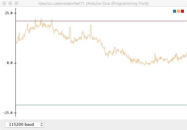 The upper line corresponds to 50.13Hz, the lower to 49.87Hz. The view shows about 4 minutes of data. See how much the mains power frequency changes. The abrupt steps of about 1 or 2 units is due to the PLL loop control and it's slightly noisy performance. I will post more fully on this subject at a later date. This work is part of an effort to make a small add-on board for the EG8010 to provide a clock that will ensure PLL locked AC output as generated by the inverter. If the inverter output is in phase with street power, when the transfer switch operates it might create far less stress in the inverter and household appliances. wronger than a phone book full of wrong phone numbers |
||||
| noneyabussiness Guru Joined: 31/07/2017 Location: AustraliaPosts: 527 |
Fantastic work there poida... I think it works !! |
||||
| poida Guru Joined: 02/02/2017 Location: AustraliaPosts: 1480 |
Part 12: EG8010 variable output frequency I have now a couple of broken EGS002 boards with gate drive ICs that were stuffed to some degree or other. It was time to see if the variable output frequency function works. I lifted pin 19 to allow me to pull it up to 5V Pin 19 now high, pin 18 low from the preexisting 50Hz setting now leaves the EG8010 at 0 - 100Hz mode. Also I lifted pin 16 and via a pot I feed 0 - 5V It works as advertised. You can get nearly any frequency from 0 to 100Hz. The output frequency variation is not continuous though. It changes at discrete intervals. I can only get 50.0, the 50.8, and 51.6 Hz, .. etc Similarly in the other direction I get 49.0, then 48.4, 47.6 Hz,.. I was wondering if I could feed the output of my PLL program into pin 16 and so lock the EG8010 output to street power. Not going to happen via this method. But it might be good for those people who might want a 240V single phase VFD. I wonder if I can drive the EG8010 via an externally generated clock? Maybe use the VCO of a CD40406 (pdf) wronger than a phone book full of wrong phone numbers |
||||
| Warpspeed Guru Joined: 09/08/2007 Location: AustraliaPosts: 4406 |
A much better way for mains locking would be to remove the 4Mhz crystal and feed a VCO into there. The grid does not vary much from 50Hz maybe +/- half a hertz at the most. That would require 4Mhz +/- 40 Khz which is not a large variation. The phase detector part of the 4046 only has to work at 50Hz so that would be fine, in fact it would be an excellent choice for a phase detector. But the VCO part of the 4046 is not going to work as high as 4Mhz. You will need something else for the VCO and there are quite a few different ways to go about that. A standard crystal just a bit higher, say 4.032 Mhz pulled down in frequency with a varicap diode might be worth a try. http://www.ebay.com.au/itm/20-pcs-4-032-MHz-4-032MHz-Crystal-HC-49-S-Low-Profile-/263039066997?hash=item3d3e59a375:g:ZMs AAOSwy5ZXDLjp Some of these low cost Chinese crystals can be a bit off frequency. I you buy a bunch, chances are you can find one that will be ideal that you can vary an even amount either side of 4.000 Mhz See how you go. 4.096Mhz is another very common and readily available crystal frequency. But there may be difficulties in pulling one of those far enough below 4.00Mhz to be useful, but it may be possible ! Another possibility would be a two terminal 4.00 Mhz ceramic resonator. These are all over the place for frequency, but if you can select one out of a bunch that works just above 4.00 Mhz, then it will be even easier to pull down lower with a varicap diode. http://www.ebay.com.au/itm/20-pcs-4-032-MHz-4-032MHz-Crystal-HC-49-S-Low-Profile-/263039066997?hash=item3d3e59a375:g:ZMs AAOSwy5ZXDLjp I have no doubt this can all be done fairly easily, but its going to take a bit of experimentation and testing. Cheers, �Tony. |
||||
| poida Guru Joined: 02/02/2017 Location: AustraliaPosts: 1480 |
2017-09-12_024241_due_pll_mains_sync.zip Part 13: Phase locked loop control with Arduino Uno and Due I've enjoyed quite a few pleasant hours devoted to exploring PLL control as implemented on Arduino microcontrollers. As at the time of writing I have very well performing code that locks on to the mains 50Hz and remains locked, tracking without any issues for days at a time. This performance is well in excess of the design goal I set - get some code that will lock to mains 50Hz to allow low stress changeover from street power to inverter power. My solar system employs a Latronics ATS40 change over switch which is a good product, doing what it is supposed to do. It takes two AC supplies, "primary" and secondary" and puts one or the other supply out the output terminals, depending on if the primary is OK or not. IF the primary is OK, it sends that out to the output. IF the primary is not usable, it switches over to send the secondary out the output. I have the inverter hooked up as "primary" and street power connected as "secondary". When the inverter restarts after gettting enough battery charge from the following day, the changeover from street to inverter occurs. It's all worked fine for 2 years. And then the Victron 3000VA inverter died. I then used a home made inverter using an inverter board from aliexpress and this lasted 2 weeks. I think there are circumstances during changeover that create large stresses on the inverter. Don't you? Should the street AC phase be 180deg different to the inverter phase, there can be large effects generated by the home appliances and the inverter toroid when the changeover event occurs. I now want the changeover to happen with inverter phase being synchronous to street AC supply. This means I need PLL control of the inverter output, to obtain sync with street. So that's the why. A bit of PLL theory We have a sync signal, which being the signal we want to synchronise our system to. We have a slave signal, which is taken from our system, to be used when comparing phase and frequency. Luckily in my case both signals are fairly clean sine waves. In testing I have seen it sync to square waves OK too. But to get decent results you must remove the high frequencies of the square wave BEFORE you sample it. You will have poor results if you let frequencies greater than 1/2 sample rate into the PLL control loop. Phase lock loops (PLL) are a filter. Nothing more or less. The phase signal is obtained in my case by multiplying the sync signal with the slave signal and putting the result through a low pass filter. The sync signal is near as can be a 50 Hz sine wave with not very much other frequencies. The slave signal is a sine wave of the slave system's output and also is nearly all one frequency. Think 95% fundamental frequency with 5% distortion for both. Multiplying two sine waves of f1 Hz and f2 Hz frequencies gives you the result of (f1-f2)Hz and (f1+f2)Hz In the case of 50Hz and, say, 51Hz we would get after multiplying (50-51) Hz and (50+51) Hz or 1 Hz and 101 Hz. Just forget about the negative result for a moment and call it positive. Should you pass this result through a low pass filter, designed to permit the 1 Hz product to pass but prevent nearly all of the 101 Hz product, you will have a clean signal that represents the difference in PHASE of the two signals. This result is then used in a control loop to change the slave output frequency so as to minimise the phase difference. It's honestly rather similar to a PD control loop. This seems simple enough, how to do it with a microcontroller... We will feel the full force of the consequences of digital signal sampling from now on. How I did it was as follows: 1 - sample both the sync signal and the slave signal at a certain rate. In this case it's 200 Hz. 2 - scale and offset the samples to be bipolar, eg the mid point of the sine wave samples will now be zero. 3 - multiply the two samples, and scale result by the loop gain. 4 - put this number into a decent low pass filter, to remove the high frequency product of the multiplication but let the low frequency parts through. 5 - Now use the filtered result and use a portion of it to correct the slave's output frequency 6 - We also need to correct the slave's output freq with a bit of the frequency error. 7 - go to 1 This is easy to implement in code. I will attach working code for both Arduino Uno and Due. Particular details of the code: step 1,2 Samples of the sync signal from the ADC range from 0 to 1024 (Uno) and 0 - 4096 (Due) These need to be level shifted so the signal varies from (-1/2 ADC range) to (+1/2 ADC range) for the phase detection arithmetic to work. This is easy to do and I code max and min tracking variables to give me the best level shift possible. step 3,4 Time to do some floating point and even the Uno is fast enough! The LP filter has to be given input with frequencies less than 1/2 the sample rate for it to work properly. The sample rate is 200Hz so if we limit our system to have sync and slave frequencies of about 50Hz +/- 1 Hz we should be OK. The street supply 50Hz is quite well regulated and only varies about +/- 0.12 Hz over the long term of a day or so. This means the phase detector's LP filtered output will be a signal with frequencies something around DC to +/- 0.12 Hz. We need to configure the LP filter to have near 100% removal of the 100Hz tone of the phase detector and I use my trusty 2 pole Butterworth biquad filter to achive this. (See previous posts of mine in this thread. I used the filter in my arduino uno inverter controller to clean up the AC output feedback) In my case I choose a filter cutoff of 0.02 with 200 Hz sample rate, this means the cutoff (-3db) is at 0.02 x 200 Hz or 4Hz This is great since it lets the 0.0 to 0.12 Hz signal through without any loss but the 100Hz signal will be cut to less than -80db. (about 1/10,000th) step 5 maintain a running total of the correction, which starts out at zero but can be any value positive or negative. call it "plllint" for phase lock loop loop integral... We need a measure of the frequency difference. Funnily enough, we can get the frequency difference between the sync and slave by looking at the change in phase error with respect to time. So if you keep a copy of the phase error from last time in the pll code run, you will have the frequency_difference = (current_phase_error - past_phase_error)/some_time_constant. And after this, let past_phase_error = current_phase_error, ready for the next time through the loop. step 6 I adjust plllint by adding a small part of the phase error and a small part of the frequency difference to it. Then convert this error integral to integer, ready for altering the slave frequency generator clock rate. That's about it. The Uno runs fine, doing the pll calculations in un-interruped time with ease. The Due is about 20x faster and has more complicated programming for the timer interrupts. How to obtain a suitable sample of the mains AC? I use a 9V AC plug pack, AC couple it with a 1000uF 25V cap, put a diode across the output. On the cathode will be the positive waveform, the anode will be zero or ground. I divide the voltage using a potentiometer. This works fine for me. I feed this into the ADC input. Search for "DC restorer" How to obtain a suitable sample of the slave? Really easy, since the slave output is a sine wave, read from a lookup table via a circular counter, just look up the current sine table value that was last sent to the DAC. One point to note is a PLL syncronises the slave to the sync with a 90 deg offset. So to get your slave in sync with zero offset, you instead offset the slave value that is fed into the PLL loop by -90 deg. It's all clear in the code. For the application of getting mains sync with the EGS002, I would need to use the output of the PLL to control a voltage controlled oscillator which would be used to drive the EG8010 instead of the onboard crystal. And we need to get a 270 deg phase shift of the mains too. But I plan to use my own systems in the inverters from now on. #define cbi(sfr, bit) (_SFR_BYTE(sfr) &= ~_BV(bit)) #define sbi(sfr, bit) (_SFR_BYTE(sfr) |= _BV(bit)) #include <SPI.h> const uint16_t PROGMEM si[201] = { 2047,2111,2175,2239,2303,2367,2430,2493,2556,2618,2679,2740,2800,2859,2918,2976, 3033,3089,3143,3197,3250,3301,3351,3400,3448,3494,3539,3582,3624,3664,3703,3740, 3775,3808,3840,3870,3899,3925,3950,3972,3993,4012,4029,4044,4057,4068,4077,4084, 4089,4092,4094,4092,4089,4084,4077,4068,4057,4044,4029,4012,3993,3972,3950,3925, 3899,3870,3840,3808,3775,3740,3703,3664,3624,3582,3539,3494,3448,3400,3351,3301, 3250,3197,3143,3089,3033,2976,2918,2859,2800,2740,2679,2618,2556,2493,2430,2367, 2303,2239,2175,2111,2047,1982,1918,1854,1790,1726,1663,1600,1537,1475,1414,1353, 1293,1234,1175,1117,1060,1004,950,896,843,792,742,693,645,599,554,511, 469,429,390,353,318,285,253,223,194,168,143,121,100,81,64,49, 36,25,16,9,4,1,0,1,4,9,16,25,36,49,64,81, 100,121,143,168,194,223,253,285,318,353,390,429,469,511,554,599, 645,693,742,792,843,896,950,1004,1060,1117,1175,1234,1293,1353,1414,1475, 1537,1600,1663,1726,1790,1854,1918,1982}; // sine wave lookup table int sc; float loopgain,plllc,pllint,pllout,oldplllc; int pint,jmax,jmin,kmax,kmin; int np,cc; float aa[10],d1[10],d2[10],w0[10],w1[10],w2[10]; long lm; void t1() // this is used to generate the slave output sine wave { pinMode(9, OUTPUT); TCCR1A = _BV(COM1A1) | _BV(COM1B0) | _BV(COM1B1) | _BV(WGM11); TCCR1B = _BV(WGM13) | _BV(WGM12) | _BV(CS10); OCR1A = 10; ICR1 = 1600; // 10 Khz, 200 step 50Hz, using a 2 x pi wave table TIMSK1 |= (1 << TOIE1); } ISR(TIMER1_OVF_vect) { int a; sc++; if (sc > 199) sc = 0; a = pgm_read_word(&si[sc]); write_DAC(a); ICR1 = 1600 + pint; // important!! update slave clock with PLL correction } void write_DAC(int i) { // write to MCP4912 2 channel DAC. This is the SLAVE signal output // 0 <= i <= 4096. the DAC expects 12 bit data. uint8_t b,c; cbi(PORTD,2); // cs low, enables tx into DAC serial port b = 0x30 + (i >> 8); // send high 8 bits of channel 0 SPI.transfer(b); c = (i & 0xff); // low 8 bits SPI.transfer(c); cbi(PORTD,3); // latch low, move data to DAC r2r ladder. DAC outputs now reflect two input 16 bit words. sbi(PORTD,3); // latch high sbi(PORTD,2); //cs high } void setup() { sc = 0; SPI.setClockDivider(SPI_CLOCK_DIV2); SPI.begin(); pinMode(2,OUTPUT); pinMode(3,OUTPUT); t1(); sbi(ADCSRA,ADPS2) ; // faster ADC conversions please cbi(ADCSRA,ADPS1) ; cbi(ADCSRA,ADPS0) ; Serial.begin(115200); Serial.println(""); Serial.println(""); np = 2; loopgain = 0.001; get_biquad(0.02); lm = millis(); } void loop() { while ( (millis() - lm) < 5) // 200Hz ; lm = millis(); do_pll(); } void do_pll() { float a,b,fj,fk,s; int i,j,k; // get 90 deg early sample of output sine. sine table is 200 samples per 2 pi cycle, so 150 samples = 1/4 wave early i = sc + 149; // i = circular buffer counter + 1/4 full wave if (i > 199) i = i - 199; // it will overflow, so wrap around if needed j = pgm_read_word(&si) - 2048; // both snyc and slave are now assumed to be full scale -2048 <= input < 2048 // get sync signal k = 4 * analogRead(0) - 2048; // i.e. bipolar // phase detection and loop gain plllc = (float)j * (float)k * loopgain; // Butterworth biquad LP filter the phase. This filters out the high freq rubbish we don't want to feedback into the loop s = plllc; for(i=0; i<np; ++i) { w0 = d1*w1 + d2*w2 + s; s = aa*(w0 + 2.0*w1 + w2); w2 = w1; w1 = w0; } plllc = s; // concoct a special feedback value, to be used to adjust the slave sine wave frequency. // maintain a running total of adjustments, each time adding a small fraction of the phase error // and a small part of the frequency error. Frequency = the change of phase over time. pllint += plllc * 0.0001 + (plllc - oldplllc)*0.01; // convert to int for fast wave table clock updates pint = (int)pllint; // get something to plot for the humans to see so they think they are controlling this process. String withScale = "-21 "; withScale += pint; withScale += " 21"; // use "serial plotter" to watch it sync up Serial.println(withScale); // and follow mains variations // need this for frequency calcs. (new phase error - old phase error)/time increment oldplllc = plllc; } void get_biquad(float fc) { float s,r; int i; float a = tan(M_PI*fc); float a2 = a*a; for(i=0; i<np; ++i) { r = sin(3.141592926 * (2.0*i+1.0)/(4.0*np)); s = a2 + 2.0*a*r + 1.0; aa = a2/s; d1 = 2.0*(1-a2)/s; d2 = -(a2 - 2.0*a*r + 1.0)/s; } } wronger than a phone book full of wrong phone numbers |
||||
| oztules Guru Joined: 26/07/2007 Location: AustraliaPosts: 1686 |
I really appreciate your work, but can't comment sensibly until I do lot more learning on the arduino coding... so far in front of me it's not funny. I would like to get all that going for charging purposes, switch over has never caused any problems with my inverters, even at extreme loads ( 6kw and more), so is not important to me. However until then, a simple induction motor should suffice as a generator with self syncing.... must do this very soon. Will save having to have a proper 240v genny and synching scheme.... ie petrol motor, induction motor... finished..... must do this to see if it is viable. ............oztules Village idiot...or... just another hack out of his depth |
||||
| poida Guru Joined: 02/02/2017 Location: AustraliaPosts: 1480 |
Part 14: EG8010 Tfb signal behaviour After the less than satisfactory performance of the second Aliexpress inverter board, failing after less than 24 hrs when under a load much less than 1000VA I wanted to make things simple.This meant I wanted to remove all chance the EG8010 would stop PWM suddenly. OZtules has a good understanding of the pitfalls of letting the EG002 board control gate drive IC shutdown, or control PWM output via current feedback. I wanted to start from the position of zero current feedback limit. I intend to deal with that eventually via a microcontroller. Oztules uses the Temperature feedback pin to control both simple on/off and over current situations. I wanted to see how Tfb works�. So I set up an EGS002 board on the breadboard with Vfb getting 3.020V to make the EG8010 soft start and remain on. Into Tfb I feed a 5V pulse once every 10 seconds or so or varying widths. I want to see what�s happening. In the following you will see Purple: Tfb signal Yellow: 50Hz light Blue: High side SPWM (sine pulse width modulation) (I use the �high res� sample function of the DSO, which applies a low pass filter to the inputs. So we see a sort of sine wave here.) We can see the EG8010 stops the SPWM in mid cycle some random time after Tfb goes high. I saw many examples of this, nearly always the SPWM stops mid cycle. After Tfb drops below the trigger voltage, SWPM restarts, under soft start control. The 50Hz does not stop. There is a minimum Tfb high pulse width that will trigger the stop of SPWM. It seems to be about 30 - 40ms. pulse not wide enough: 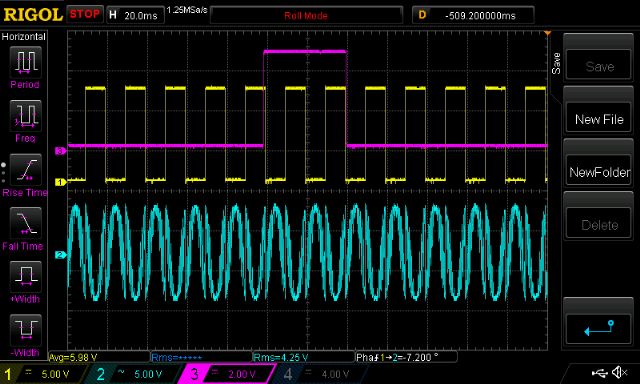 all that follow have the pulse wide enough. 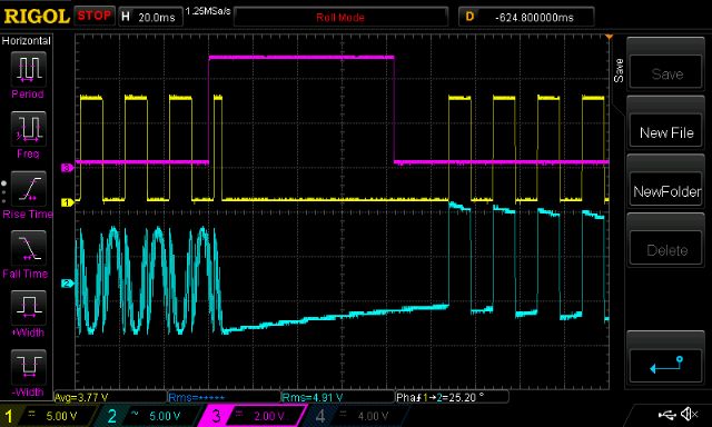 this is what happens if the soft start is still ramping up. 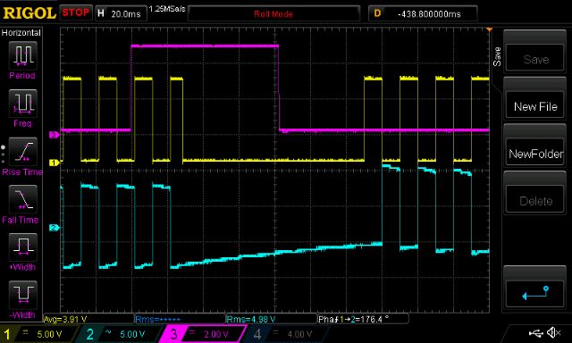 In the following you will see Purple: Tfb signal Yellow and light Blue: High and Low side SPWM 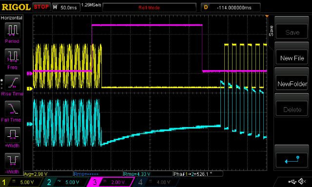 I hope this is of some interest to us here. wronger than a phone book full of wrong phone numbers |
||||
| Warpspeed Guru Joined: 09/08/2007 Location: AustraliaPosts: 4406 |
I have just received a couple of EGS002 boards from China. Have been feeling a bit left out of it all, and cannot let you guys have all the fun... Fired up one EGS002 only just now, still have a great deal to learn about these, but a few initial observations about current limit generally. The Ifb (pin1) appears to do two things, it disables the two IR2110 drivers, which will be a fairly fast and violent on/off action. It also connects to the EG8010 chip via R27 which is not fitted to either of my boards. There is also no value for R29 on the schematic, and I notice from many pictures I have found of the EGS002 board on the internet, R27 always seems to be missing from all the boards. Shorting out R27 has the effect of allowing the EGS002 board to soft start once the Ifb input has been removed. Ifb then has a fast off (via shutting down the IR2110 drivers) and a soft slow recovery similar to a normal power up. That has to be good. I cannot imagine why this soft recovery has been deliberately disconnected by the manufacturer, but it appears that it has now been a long standing production change. Anyhow, I think linking R27 and driving Ifb from an SCR triggered by a current transformer as previously suggested here on the Forum, may be the best way to go. The Tfb input worries me a bit, as it may not offer a fast enough shutdown. Using just Tfb does not shut down the IR2110 drivers which I think is a necessity. Over temperature shutdown need not be fast. Shutting off the IR2110 drivers will be very fast indeed but I don't trust the EG8010 board for fast turn off, but the soft start it provides is certainly very nice. We need to think about the rate of current rise through the mosfets under fault conditions. If both upper and lower mosfets turn on simultaneously, its obviously all over in a giant flash and a bang. Insufficient dead time is unlikely to be the problem there. We may also get spurious simultaneous turn on from noise, especially if the EG8010 does not get very clean stable power, or there are serious grounding issues in the whole system. That all needs to be thought through very carefully. The other issue is high fault current from excessive loading on the output. If we crowbar the output, the current rise through the mosfets will not be instantaneous, but will be checked by any series inductance. That is the value of fitting a large serious non saturating choke immediately after the mosfets. From the inductance of that choke, and the applied dc voltage, we can come up with a figure of amps rise per microsecond, under worst case dead shorted output. Assuming a nominal supply of 48v and a nominal 48uH choke, the maximum rate of fault current rise can not exceed 1 amp per microsecond. And may well be slower. So current limit needs not be super fast, say a few microseconds or tens of microseconds. We certainly don't need to stop the fun in nanoseconds. Even the simplest over current shut down HARDWARE should be well up to that, assuming there is a suitable non saturating series choke fitted ! But software, depending how it has been written may fall sadly short. An over temperature shutdown has no natural urgency about it, it may only be tested once each program loop. In fact it could be worse, it may need to be tested several times before it decides its a real over temperature event. Looking at that last picture in the previous post, Tfb appears to need about half a mains cycle before it shuts down, maybe 10mS ? That is worryingly slow. Cheers, �Tony. |
||||
| poida Guru Joined: 02/02/2017 Location: AustraliaPosts: 1480 |
HI Warp, I only just saw your recent reply (above) I approach the current limit problem differently. I am OK with high current that lasts for a few cycles. I know and have seen very high current during the load switch-on events. These peaks exist for fractions of a 50Hz half cycle. I am OK with these too. I let the DC supply fuse/CB do their job. I let the fact that I have 3 x 210 Amp mosfets look after transients that are about 200A max (thanks to ESR of the transformer primary, choke, Rds-on etc) mean it will survive. Exact or correct numbers are not my speciality. My rationale is: do I want to interrupt things during the very high peak current incident? If so, how and will it cause more issues? I think I don�t want to go there. My view is let it go and choose mosfets good for large peak current. Also try to mitigate the parasitics. And let short term problems pass. This ends up requiring huge over sized H bridge inverter designs feeding loads that rarely exceed 1500W. I�m aware this is a brute force method but I am a lazy hacker. You are an electronic/electrical designer. So the way I use the EGS002 boards is to disable all current feedback and disconnect the gate drive shutdown pins from the rest of the board (by cutting the trace). I control on/off via the Tfb pin only. I�m happy with this. When first playing with the ESG002 based inverter board I looked at the two current limit sub systems. One was used to interrupt gate drive via output of a comparitor taking the fast changing DC current. Another circuit was using a low pass filtered sample of the DC current and again stopping PWM output, this time via the EG8010 only. During testing on the bench, using small AC loads up to 500W, and adjusting the high current limits, I nearly had the toroid jumping up and down on the table top from the sudden disabling, then reenabling of gate drive. It just didn�t seem right. These sudden power impulses appeared to me to be something to avoid. Again I say, we will get large current impulses from motor start up, switch-on of lighting, switch-on of SMPS driven appliances, etc. The last thing I want to do is interfere right when the current is as it�s maximum. wronger than a phone book full of wrong phone numbers |
||||
| poida Guru Joined: 02/02/2017 Location: AustraliaPosts: 1480 |
Part 15: When 47uH is not the same as 47uH I have had some good times and bad times with my home brew, most poorly finished inverter. The main power board is one of these 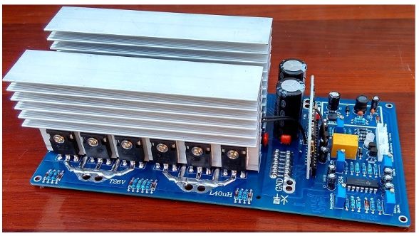 3 x Hy4008 210 Amp mosfets per leg of the H bridge. I enjoyed approximately 2 1/2 weeks life from the first unit. I bought another one and it went for less than 24 hrs. The bag of spare HY4008�s arrived shortly afterwards so I replaced all, checked gate diode and resistors, etc, replaced the EGS002 since it had blown both the IR2110 and the EG8010 and gave it another go. It lasted not quite 2 days. Something is wrong. I modify the EGS002 so that there is no current limit control, the only way it switches on is via the 5V supply coming up, causing the 3 sec slow start. The only way it goes off is when the 5V comes down. No cause for concern. I use an Aerosharp 1500VA inductor core, with 13 turns of 3 x 6mm cable. This gives me 47uH and a very low ESR. 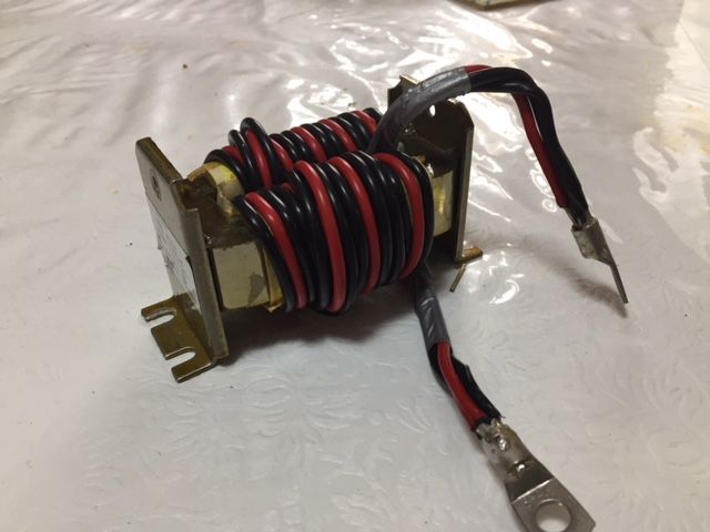 The board feeds a 37V primary on a 3kVA Areosharp toroid. There is a 47uH choke in series. The secondary has a 5uF 450V cap, then via a 16A CB to a dual GPO. After rebuilding the better looking of the two boards, again needing a new EGS002, I put the DSO on the primary winding, NOT the output of the inverter board. This means the two probe points are the two primary winding terminals, one of which is where the choke connects. I was wondering what is causing the failure. The boards last for days then fail. This means it�s not a simple design fault. The problem is more to do with operating limits of components exceeded. Yellow is low side gate drive, used for sync. Blue is primary winding voltage. First we see the Aerosharp choke at idle and under approx 400W load. See the overshoot and undershoot on each transition from on-off and off-on. idle 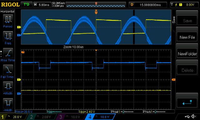 load  Next is the E65/32/27 ferrite core with 1.5mm gap, also 47uH. There is no over/undershoot at all. idle 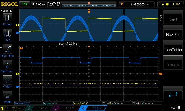 load 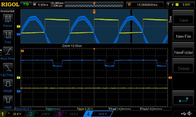 It does not seem much but it is clear to me there is a difference when I connect one or the other 47uH choke. Last night I saw the inverter deal with a large load, bordering on short circuit and survive when the defective blower fan of the wood heater was switched in. I doubt it would have made it through that event without blowing up. I used the Areosharp choke on the bench when bringing up another but different inverter board, this time using 5 x HY1908 (90 Amp) per leg. Usual test conditions (EGS002 with soft start, no current control, 27V DC, 1500VA toriod, 140W load) It started OK with no load. I switched in the 140W test load a few times and one leg at least has blown. I have not damaged any boards on the bench before. It�s so easy to damage things by exceeding something. I think it�s not about current limits being exceeded, I think it�s a excessive voltage thing. The E core ferrite choke is appearing to me to be the magic sauce in the home brew inverter. They reduce the speed of the fast voltage changes seen by the 4 legs of the H bridge. These voltages correspond to Vds or the voltage between drain and source. Admittedly most modern mosfets have construction such that they can widthstand voltage larger than Vds (called �avalanche�) but I think there are limits to how much energy can be absorbed before failure. Fast voltage changes also contribute to cross conduction thanks to dv/dt inducted turn-on. I wonder.. In summary, I think I found the cause of the 3 failures of the inverter boards. Iron cored chokes. Use Ferrite cores due to their capacity to reduce high frequency energy passing through. Even if the iron core choke inductance seems enough, they pass too much high frequency energy. This characteristic is not shown with the inductor testing we do. I attempted to show how inductance changes with frequency testing at 1kHz, 10kHz, 100kHz and 1MHz but my skills were not up to the task. I saw small changes in inductance but not enough at 1MHz to explain the iron core's difference. MAybe I need to go to 10MHz..dunno. I may have spoken too soon and this board no.4 will fail tonight. (Murphy�s Law) I�m OK with that, it will force me to look harder, think better and keep learning. wronger than a phone book full of wrong phone numbers |
||||
| Madness Guru Joined: 08/10/2011 Location: AustraliaPosts: 2498 |
Forget Murphy, O'Shannassy's law overrides Murphy as O'Shannassy said Murphy is an optimist. There are only 10 types of people in the world: those who understand binary, and those who don't. |
||||
| Warpspeed Guru Joined: 09/08/2007 Location: AustraliaPosts: 4406 |
Is that the same dude that went to London to blow up a bus. And burned his lips on the exhaust pipe ? Cheers, �Tony. |
||||
| noneyabussiness Guru Joined: 31/07/2017 Location: AustraliaPosts: 527 |
Poida, i dont know if it of any relevance, but i had a 10kw inverter (based on the PJ control card) and i could not get it to work... blew every power board i threw at it (many mosfets met there doom) but on the smaller transformers i was testing with it would run fine, as soon as i connected it to the monster transformer it would self destruct. They had the same " voltage " input/output and the big tranny was professionally wound... i spent months trying to figure out why it would blow up. Even with brand new PJ gear it would last tops a day... To cut a very long and painful story short, i ended up (under advice sort of) putting 10 .1 ohm resistors ( so .01 ohm total resistance ) in series with the primary. .. that thing has seen over 11.5 kw for over half an hour without missing a beat..😎 I think it works !! |
||||
| Tinker Guru Joined: 07/11/2007 Location: AustraliaPosts: 1904 |
Now that is interesting. With my dual stack toroid I used very heavy gauge cables, two in parallel, to wire up the primary and battery connections. It blew all the Mosfets on switch on. Tinkered with it for a while, smaller toroid, different drivers, less capacitors, you name it, but just had mixed success. Nothing I would call reliable. I then re built the whole caboodle in the usual one long, two short heat sink configuration and it ran over 6KW. BUT, that was with much longer cables to the battery and primary & 2 chokes, as in a rough bench top test set up. It should not be too hard to introduce 0.01 Ohm in series, just a steel washer between the connection lugs would do I should think. I shall try that when I connect it all up again (making a case for it presently) and see what happens. I won't double up with the inter connection cables either this time. Klaus |
||||
| The Back Shed's forum code is written, and hosted, in Australia. | © JAQ Software 2026 |
