Notice. New forum software under development. It's going to miss a few functions and look a bit ugly for a while, but I'm working on it full time now as the old forum was too unstable. Couple days, all good. If you notice any issues, please contact me.
Solar Mike Guru Joined: 08/02/2015 Location: New ZealandPosts: 1212
Posted: 11:53pm 23 Oct 2017
Copy link to clipboard
Print this post
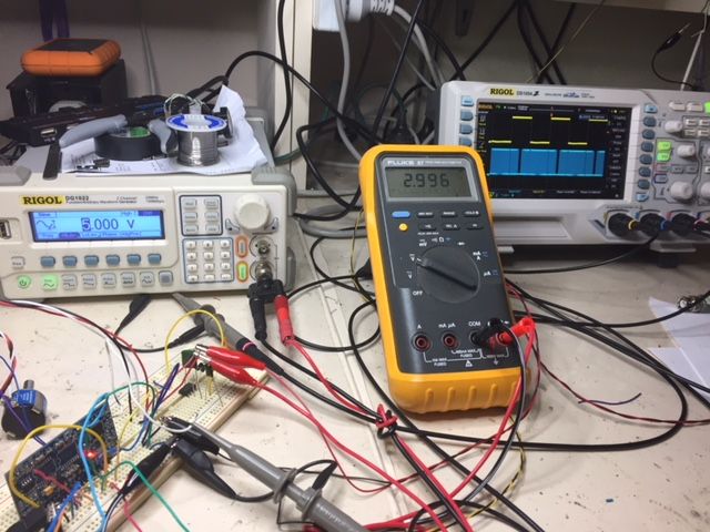
I recently ordered a couple of those cheap EGS002 driver boards for use in a small 24V inverter, they turned up yesterday, had a good look over one of them with a jewelers eye glass; located a few issues, that will require fixing before use.
1: Two pins on one of the IR2113S (not IR2110) mosfet drivers had distinct dry joints, pins were sitting almost dry above the tracks. 2: 12 Mhz Crystal can was touching top tracks running under it, pushed it a bit sideways to straighten. 3: Bootstrap caps one was tantalum, the other like a big chip type, these are extremely dodgy, tants are not suited for this application, same probably goes for the other; they need replacing with proper low esr electrolytics.
If this board was used, it would cause all sorts of issues, so it pays to check and I wonder how many of these inverter problems are caused by problems like this.
Cheers Mike
Revlac Guru Joined: 31/12/2016 Location: AustraliaPosts: 1276
Posted: 02:25am 28 Oct 2017
Copy link to clipboard
Print this post
I have seen some bad joints on some circuit boards, I used one of those usb microscopes, found a smd resistor that was shot. So its a good idea to check these things, destroyed a few fets because of a dry joint.
There is some EGS002 boards for sale with proper capacitors on and I did see another board that had a 555 ic connected, still no schematic or description why its there.
I will be changing one of my EGS002 boards to proper caps.
AaronCheers Aaron Off The Grid
poida Guru Joined: 02/02/2017 Location: AustraliaPosts: 1476
Posted: 12:15pm 03 Nov 2017
Copy link to clipboard
Print this post
Part 16: BYO clock for the EG8010
As a result of my past trials and testing, I have a few defunct EGS002 boards. One of which still has a functional EG8010. "you'll do", I thought.
I have a need to achieve sync of the EGS002 output with our local street power. This is to aid in the event when the house switches over from using street power to using inverter power. At present this event occurs at any time in the 50Hz cycle. Sometimes bad things happen. I plan to build a mains sync subsystem, creating a clock for the EGS002 such that it remains locked with mains power.
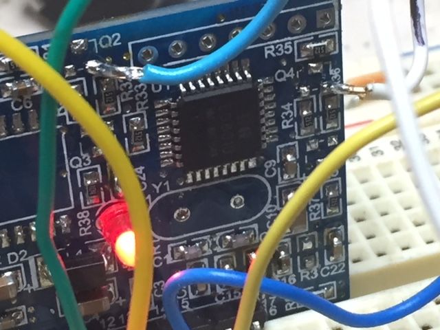
After removing the 12MHz crystal, I attached two wires to the pads where it was located pin 10 and 11, with a 220nF ceramic cap in series with each wire as AC couplers. I set the function generator to output 12 Mhz with a low level of 0V, and high of 5V. I attach the fungen ground to EGS002 ground. The fungen output can be put on either pin 10 or 11. Apply power and it works.
Sometimes it does not start up, maybe due to bounce when I manualy attach power. In any case beware of letting it sit powered up but not running. I saw the EG8010 chip get so hot as to burn my finger once. That was when I put the fungen ground on pin 10 and fungen output on pin 11 in an unsuccessful attempt. It needs to oscillate.
Anyway, I�ve seen it run down to 2Mhz, up to 20Mhz. Time to have a look at tunable ceramic resonator circuits. Crystal oscilators can�t be tuned over a wide enough range for my application. Typical tune ranges of +/-100 parts per million range is far less than the mains freq deviation present here in Melbourne. I�ve seen it down to 49.85 and up to 50.15 on a daily basis. 100 ppm is equivalent to 49.995 to 50.005 Hz range.
wronger than a phone book full of wrong phone numbers
oztules Guru Joined: 26/07/2007 Location: AustraliaPosts: 1686
Posted: 12:37pm 03 Nov 2017
Copy link to clipboard
Print this post
Damn you do some interesting stuff. Am following your exploits.
I assume it will sync to the mains, and this should be nice, but when you lose the mains ( switch off from mains to inverter ), I think you will need to do some interesting ...something.... to avoid sudden switching pulses hitting the torroid. We know that this can be fatal... wondering how you can implement that, or even off grid usage without the grid running in parallel ( using it for freq)
I will keep watching with much interest.
Thanks Poida.
On another note, I think the discussion around the VFB is mostly pointless apart from knowing when it actually looks at the VFB voltage as an academic exercise. It wants to see a voltage with which to compare so as to set a pulse width. It does not care about anything else but the amplitude it is given whenever it looks.
If we get too cute with pulse VFB trying to match the read points, it will be most likely unstable, and may well lead to total instability.
It is best to just rectify the output sample, and chose a 4uf or whatever you want to set the hysteresis you need for sensible operation.
I found that the best for me is in the 4uf with the resistors on the board ( somewhere here). This gives very fast control of the output voltage ( even 5kw dumps don't seem to bother the lights), and most importantly, very stable output.
Tinkers comment re: noise is very relevant, as any downward inflection at the read time will produce what may be a disproportionately wide pulse width... leading to unstable operation, and maybe fet damage for no good reason.
I don't think trying to synchronize to the read point is wise in any way. I think it is being over thought, for what is really a very simple VFB requirement.... just my thoughts on it.
........oztules
Edited by oztules 2017-11-04Village idiot...or... just another hack out of his depth
poida Guru Joined: 02/02/2017 Location: AustraliaPosts: 1476
Posted: 12:57pm 03 Nov 2017
Copy link to clipboard
Print this post
Oz, I agree re. Vfb. Just give it something, smooth away the high frequency rubbish and set a trimpot voltage divider to make the inverter give what you want. (I like 230V AC)
When mains drops out, my program will detect no sync and smoothly change to an internally generated 50Hz. The program is an oscillator with frequency and phase driven by an error signal. I will build a ceramic resonator circuit to do the same thing, with a frequency tuning input that when set at (say) 2.5V will produce 12Mhz.
I think there will be no problems at all. When mains reappears, it can resync. The problem exists only when change over from mains to inverter. The other change, from inverter to mains does not create stress in inverter components (maybe household items such as the aquarium pump with it's syncronous impeller or a fridge..) This will not change over when street power is not present.
When playing with the PLL sync system on the bench (at work - shhh, don't tell the boss) I see the output of the PLL remain in sync when I pull the mains sample input out of the ADC pin socket sometimes. The board and program still finds something to sync to, probably from picking up mains hum from the mass of wires I usually have hooked up to the arduino board.Edited by poida 2017-11-04wronger than a phone book full of wrong phone numbers
Madness Guru Joined: 08/10/2011 Location: AustraliaPosts: 2498
Posted: 01:21pm 03 Nov 2017
Copy link to clipboard
Print this post
Good work Poida.
Something I will mention again for those wanting to sync with a generator for off grid. My old Trace inverters allow up to 3 KHZ either side of 50HZ. Anything greater than that and it disconnects from the generator. These inverters use a 30A relay and when it is happy that it is in sync it closes the relay to connect AC to the transformer. The same inverter also can back feed into the grid but is not approved for that in Australia, something to do with how it detects when the grid goes down.
If you could come up with a solution that includes that slightly wider frequency range I for one would like to make use of it. I am sure there are others that would find this useful too.There are only 10 types of people in the world: those who understand binary, and those who don't.
Warpspeed Guru Joined: 09/08/2007 Location: AustraliaPosts: 4406
Posted: 01:25pm 03 Nov 2017
Copy link to clipboard
Print this post
I played around with frequency pulling ceramic resonators some time ago.
The trick seems to be to buy a whole bunch, the frequencies will be all over the place. Use the highest frequency resonator out of the batch.
There was never any problem pulling the frequency low, it was reaching the high end that proved quite difficult.
I managed to get 497Khz to 503Khz from a 500Khz resonator, with 0 to +10 volts using two BB112 varicap diodes (35 to 440pF each) which is what I needed for my application. Divided down to mains frequency that would give +/- 0.3Hz which is plenty.
It should work equally well up at 12Mhz. Surprisingly the frequency shift versus voltage ended up being a lot more linear than I expected. +5v producing a very stable 500 Khz.Cheers, �Tony.
Tinker Guru Joined: 07/11/2007 Location: AustraliaPosts: 1904
Posted: 01:41am 04 Nov 2017
Copy link to clipboard
Print this post
A last comment about VFB, it may be pointless for some to discuss this but to me it helped a great deal to understand why and how it does what it does. So, thanks guys. I'm sure I'm not the only one having benefited from this discussion.
And, it managed to solicit above another point of info about which I was unaware of. Namely, the location of the little transformer with relation of the secondary capacitor. I always thought it odd to stick it on the side of that little transformer, now it appears there is a good reason for that.
Since I'm building my inverter "from scratch" I really did not want to copy oztules PCB layout. Om my version, the mains circuit (little transformer, current sensor, rectifiers) are on a separate board. The capacitor is directly on top of the big toroid. Luckily with my latest arrangement these parts are closely together, only some 100mm of heavy gauge wire is between the little transformer and the capacitor.
My pre testing (no toroid/ Mosfets connected) of the control board is just about complete with all EG8010 functions working well. I did power the 230v side of the little tranny from mains and used the rectified 12v output to provide VFB.
There was some high frequency noise on the very peaks of the cycles and I could reduce this to ~50mV pp by simply loading the rectified 12V secondary with 560 Ohm. Giving the little tranny something to do so to speak.
Hi, i'm new here and i was atracted to this discussion because i was invertigating what could go wrong with my newly bought egs002 modules with IR2013 and how should i improve it before i would fire it so that it won't fail. So please help me understand the details of this kit !
R27 is missing on my modules too, it's only weird that one module has a 2nf for C19 , while the other has no capacitor for c19.The values are a bit off than the original values but they seem to work. After reading all this article i kinda understand why.
Please let me explain what i want to do with it and maybe give me the best ideas, but please don't laugh at me if it sounds silly!
I want to use one of the modules to drive a 13 watts/220v ac hysteresis sincronous motor that spins the platter of a good vinyl turntable .That's exactly what i need to drive: a 13 watts motor , no more than that.
I built first a system that had a step down transformer, an audio class ab amplifier driven by a variable 40...81hz sine oscilator based on xr2206 and another step up transformer to drive the 220 v ac motor.I took the feedback for the audio amplifier from the primary of the step-up transformer as it was more stable and gave less vibration to the motor. That controller was 10kg and lost 40w of heat on the heatsink to be stable enough.Well...some audiophyle guys still consider that aproach the best, but i find it silly.
I thought of a radical change, to use a VFD system that would be small enough to get inside the turntable and would operate straight from the mains 220v(230v). EGS002 looks perfect for that.It may not allow me find the perfect speed as the output has descrete values but at least i hope it will provide me a perfect 50hz sine voltage.
I read all this article and thought to use 2SK1119 as output transistors, the smallest i have to do the perfect job.The motor takes just 60ma.
I thought though that the NO IFB solution and either the TFB or just 5v power-on/off controll would still be great as i don't want to have any problem with the turntable motor which is kind of a rare and expensive one in terms of very low vibration specs.
My first concern is the fact that if you lift the IFB pin you need to ground the op amp input to have the IR2013 ON and i don't know if you did it.
I also thought to ask if all these problems you mentioned have anything to do with the fact that the IFB output is not only driving the SD pins of ir2013(in my case), the SPWM soft start if the r27 is in his place , but also the IFB input pin 14 of the eg8010.
It may be the case that there are too many superimposing events that stop this module to work great.So if the spwm is disconected might be also because the ifb pin 14 is doing something too to shut the system down.
Another point is that if you let the R27 disconnected C30 is just 1nf series with 10k and maybe the soft start needs to be a bit longer .
The opposite of it is that if r27 is at his place should it be a short as we have a 1nf capacitor on the op-amp output?
Another aspect i would like to adress is the fact that i would preffer the output transistors to be separated by transformers from the drivers or at least the drivers to be separated from the eg8010 so that no mistake happens.What do you think about this aspect?What do you think it would be the best aproach in terms of total safety?
I am sorry if my english is not at it's best and also if my electronics knoledge isn't that good.
Warpspeed Guru Joined: 09/08/2007 Location: AustraliaPosts: 4406
Posted: 10:53am 04 Nov 2017
Copy link to clipboard
Print this post
I just placed a short across R27, the C30 capacitor I suspect, is just there to block any high frequency noise. Its not critical, and could be removed.
With R27 bridged, the Ifb now instantly turns off the IR driver chip, and when Ifb falls below the threshold the PWM soft starts via software, its not C30 providing the soft start action. It soft starts very gently just as it normally does at initial power up.
With R27 removed, Ifb only works on the enable pin of the IR driver chip, and its a very sudden and violent all or nothing on/off action. I have no idea why R27 was removed.
The way I have done it, is to use the SCR latching circuit others here are using that turns off the PWM pretty fast. Then wire a normally open push button directly across the SCR as an over current reset button. When reset is pushed, the system soft starts, but only if R27 is bridged.
Pushing this reset button at any time instantly shuts down the PWM, and it soft starts back up again.
Many ways to skin the Ifb cat...Cheers, �Tony.
oztules Guru Joined: 26/07/2007 Location: AustraliaPosts: 1686
Posted: 10:57am 04 Nov 2017
Copy link to clipboard
Print this post
"And, it managed to solicit above another point of info about which I was unaware of. Namely, the location of the little transformer with relation of the secondary capacitor. I always thought it odd to stick it on the side of that little transformer, now it appears there is a good reason for that."
No.
The capacitors next to the tranny are for wave shaping, and as it turns out for you now, they are best placed on the output of your torroid... where you now have them.... sot thats a good thing...... They do not have any direct influence on the VFB, they make a sine wave out of the hash from the torroid.
The 4uf I was referring to is the 4u7 on the rectified side of the little tranny. I know you wanted to be different, but if you look at my board, it has two decoupling and filtering parts to it.
First it is rectified, then it goes through 7k5 resistor, then it goes through the trimmer, which is 1k8 from ground, and the trimmer is 500r.
It then has 4u7 across the output of the trimmer.... to ground...so stage 1 low pass filtering and decoupling is achieved, then it goes through another resistor, and to the VFB pin as well as another decoupling/filter cap of small capacitance to chop off the HF ripple that may be there.
The only reason I have the bigger 4uf of caps on the control card is for replication simplicity. There are at least 16 of these things running 24/7 across the island... so we are probably in the 30 or more run years now across the range.. probably closer to 40. They run everything and anything, as you will have found with your powerjack unit. Hopefully your new one is ready for prime time too now.
They are incredibly reliable, and cause me no problems ( except for the known battery under-voltage problem mentioned earlier).
So mine are designed to be cookie cutter construction, they all work first time, they all work completely reliably in the field. I had to make it so there was very little chance for variation in construction. You will note your power jack version worked out of the box, so do mine. There are good reasons to use the circuit boards to do as much as you can, with as few interconnects as possible.
I hope that clears up the misunderstanding with the caps. It won't hurt to put a 100n to ground on your VFB pin to catch the HF hash that the 4u7 misses.... and twist your interconnect wires to keep stray induced voltage and noise out of them if your concerned with noise.
........oztulesVillage idiot...or... just another hack out of his depth
I think that , if you place r27 you still have some time constants given by r27/r10/c30 on one side and r4/c19/r26. c19 is missing on some boards, has values spread between 1nf to 10nf on various schematics along with different values for r4. one of my boards has 2nf, the other nothing , the same r4 and r26 (100k)is there to speed up the op-amp comparator that shuts down the IR2013.
Maybe IR2113 is supposed to be on/off very quickly,but c19 should tame it or just keep it clean .
I understand now that when ifb voltage at pin 14 is up due to high current , eg8010 stops suddenly, maybe even faster than IR2113 as there's another op-amp in between the ifb signal and SD pins of IR2113.
If R27 would be there, spwm could have several restarts as there's no histerezis on the U4b op-amp that gives the spwm signal with a short r27 and no meaningfull value for c30 and anyway that would mean aditional delay to the internal delay of spwm. So they completly removed that r27 and saved the cat.
I think either i will go with no IFB , pin 6 of u4 grounded through that 1k of R7 resitor and power up and down straight from 5v power supply, either i would use the ifb or tfb to power up/down and keep the IFB out of the system. TFB has it's own delay while Ifb allows it.
For 60ma there should be no other problem, but accidental overvoltage and a transformer separatin should save me some boards.So i'm looking now how to better separate the drive from the output. Edited by dreamth 2017-11-05
Warpspeed Guru Joined: 09/08/2007 Location: AustraliaPosts: 4406
Posted: 01:22pm 04 Nov 2017
Copy link to clipboard
Print this post
As you will be driving one specific motor load only, something crude like a fast blow fuse may be all the protection that is needed.
Its a bit different with a high power general purpose inverter, where there is no way of knowing what kind of horrible load or fault current may be expected. Edited by Warpspeed 2017-11-05Cheers, �Tony.
Tinker Guru Joined: 07/11/2007 Location: AustraliaPosts: 1904
Posted: 11:04pm 04 Nov 2017
Copy link to clipboard
Print this post
Thanks oztules, for clearing that up. Somehow I missed that 4u7 when I reverse engineered your PCB to see what makes it tick. Unfortunately the "no circuit diagrams" comment left me with no choice...
Anyway, I have everything else you mentioned duplicated on my VFB circuit and its a simple task to replace my 0.1uf cap used at the first stage with a 4u7 cap. The 100R resistor from pot wiper to pin 13 & 0.1uF to ground is already there.
I will check tomorrow if that made that 50mV hash disappear.
The inverter is still waiting for the LCD combination power display module/meter to arrive. I had bad luck with the 4 display LED ones you show on your pics, two of them had lost a segment or two from the 7 seg LED's. Looking inside I found solder globules shorting tracks... They did work for a while though.
Inverter update with final pictures coming soon...Klaus
poida Guru Joined: 02/02/2017 Location: AustraliaPosts: 1476
Posted: 08:04pm 06 Nov 2017
Copy link to clipboard
Print this post
Part 17: That Powerjack I bought. It has a primary choke. I bought this a while back when the Victron poo�d it�s pants. The primary choke is 2 turns through a Green ring of unknown provenance. Two turns measures as 28uH at 1KHz via the LCR meter. OK, maybe the PJ people know what they are doing. For sure, their powerboards are very strong. Do they know much about primary chokes?
Since I have no interest in horse racing (my view is that the jockeys are drugged up on speed and the horses drugged up on whatever passes the urine test this year) today I got busy instrumenting the PJ 6000W LF.
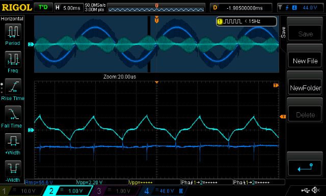
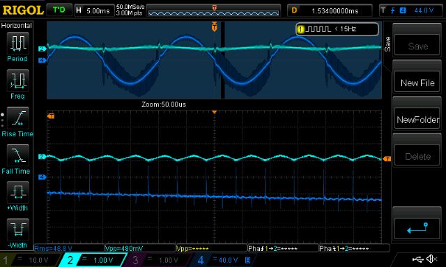
First we see the primary winding current waveform at idle, in light Blue and AC output in dark Blue. Primary current equates to 10.6mV/Amp and the DSO gain is 1v/div. This means these are sharp peaks +/- 100 Amps. The time period where the bottom trace is zoomed into is just before zero cross of the output AC. At the top of the AC output cycle, the primary current drops back to something more sensible. But I estimate that 2/3 of the time, the primary current is peaking at 100A. Just What The Actual F@#k?
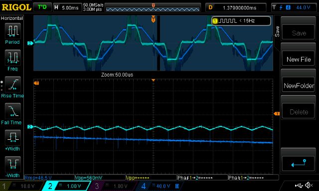
This shows the primary current under a load. (The 3 speed brushless DC motor pool pump with it�s poor power factor.) Primary current is much more than the sensor can handle so we see it clipping. Still the huge current spikes can be seen.
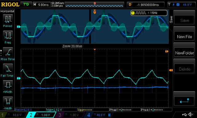
I next retain the 2 turn choke and add in series a nice E core ferrite, 6 turns 47uH, wound with 6mm2 wire. Idle - no load. Now this looks more like it.
And for completeness sake, under load.
I now tested both inductors using the di/dt pulse test method. This is useful in that it gives an indication of saturation current for the device under test. E core, 47uH gave me 112us, 29.6A, 12V supply, so L = 12 x 122E-6/29.6 = 45uH Saturation starts at about 35A Ring, 28uH gives me 7.7us, 10.2A, 12 so L = 12 x 7.7E-6/10.2 = 9uH The LCR meter gave me 28uH but the pulse testing is 9uH! Saturation started at about 15A.
DC supply current during idle improves using the E core choke, from 1.0A to 0.4A (50W to 20W..) These E core chokes are the way to go. The one I used is RS part no. 6479389 E70/33/32 N87. It has no gap so I ground down about 0.5mm on the belt sander. Cost was $14 wronger than a phone book full of wrong phone numbers
oztules Guru Joined: 26/07/2007 Location: AustraliaPosts: 1686
Posted: 10:08pm 06 Nov 2017
Copy link to clipboard
Print this post
Powerjack did not have any chokes at all years back. I fell into conversation with my seller, and showed her my modifications and the blurb that went with it.... from guess who bought a powerjack thread. ( http://www.anotherpower.com/board/index.php?topic=902.0 )
Their engineers decided I was onto something with the Ecore, and then fell back to the rings from the looks of it.... probably space and price was a problem for them. I also got them to place their boards on Ebay... they were then less than $200 inc postage for the set.
I was apparently lucky in my choice of material and device at the time.
Now you have turned your attention to it, I can at least see what I lucked into
..........oztulesEdited by oztules 2017-11-08Village idiot...or... just another hack out of his depth
Tinker Guru Joined: 07/11/2007 Location: AustraliaPosts: 1904
Posted: 12:04am 07 Nov 2017
Copy link to clipboard
Print this post
I used an E65 core, sourced from ebay/ Romania as had oztules and many others.
Grinding it down to make a gap seems to me to be doing it the hard way. Why not just insert a suitable thickness material at all three of the mating surfaces?
These cores are noisy with no gap, no matter how hard they are clamped together.
My gap is made by gluing heat resistant tape (klapton?) on each pole face and trimming it with a scalpel. So, when assembled, a double thickness of that tape makes the air gap. The E core is now very quiet.Klaus
poida Guru Joined: 02/02/2017 Location: AustraliaPosts: 1476
Posted: 05:11am 18 Mar 2018
Copy link to clipboard
Print this post
Part 18: primary current during transients
This is just a short note to show what happens to primary winding current when I switch on my test load (167W incandescent globes at 235V AC)
DC supply is 27.5V I measure aprox. 14.8 Amp RMS in the primary which runs at 12.9V AC 14.8 x 12.9 = 190W. Near enough.
I record primary current this time with a current transformer and 100R shunt resistor. It calibrates to about 0.095V / Amp
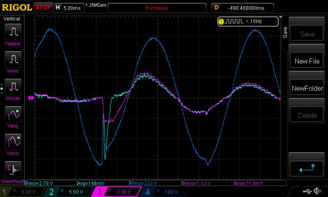
Here is the switch on event
Light Blue is current transformer Pink is LEM current sensor Dark Blue is AC output
That peak is 15V on the CT which is about 158 Amps The LEM current sensor saturates the output at about 2.5V which is 59 Amps
So we see a switch-on transient of 158 A when a 167W load is switched in but when steady state, it needs only 21 Amps peak.
Imagine the kinds of peak primary current when Oz torture tests his inverters with the welder.. Or we turn on inverter driven motors in the split system A.C.
I wonder if having just a little primary winding resistance is a good thing.wronger than a phone book full of wrong phone numbers
johnmc Senior Member Joined: 21/01/2011 Location: AustraliaPosts: 283
Posted: 07:22am 18 Mar 2018
Copy link to clipboard
Print this post
Good Day Poida,
Thanks for the update Will be interesting to see what is the affect, of a inductive choke, on the secondary.
cheers johnjohnmc
Tinker Guru Joined: 07/11/2007 Location: AustraliaPosts: 1904
Posted: 10:17am 18 Mar 2018
Copy link to clipboard
Print this post
Thanks for your informative updates poida.
I use two primary chokes, one the high frequency 3 or 4 turn ferrite affair on the high side and a non saturating 9 turn choke on the low side.
This seems to work for me, switching on an abrasive cutoff saw on top of a steady 4KW load has not killed it yet. Klaus
Page 8 of 48
Print this page
The Back Shed's forum code is written, and hosted, in Australia.