
|
|
Forum Index : Electronics : Various aspects of home brew inverters
| Author | Message | ||||
| Warpspeed Guru Joined: 09/08/2007 Location: AustraliaPosts: 4406 |
[quote]I use two primary chokes, one the high frequency 3 or 4 turn ferrite affair on the high side and a non saturating 9 turn choke on the low side.[/quote] Definitely the very best approach to all of this. Cheers, ĀTony. |
||||
| tinyt Guru Joined: 12/11/2017 Location: United StatesPosts: 559 |
Cold incandescent lamp inrush current is about 7 to 10 times operating current. So, in my opinion, the observed currents are accurate. |
||||
| poida Guru Joined: 02/02/2017 Location: AustraliaPosts: 1476 |
Thanks tinyt, I was wondering if this measurement was within reasonable bounds. wronger than a phone book full of wrong phone numbers |
||||
Madness Guru Joined: 08/10/2011 Location: AustraliaPosts: 2498 |
One of the biggest start currents I have had is with an abrasive metal saw with a 10A universal motor. There are only 10 types of people in the world: those who understand binary, and those who don't. |
||||
| poida Guru Joined: 02/02/2017 Location: AustraliaPosts: 1476 |
I just tried this with a 60W Apple "magsafe" macbook powersupply. This is an offline switching PS. 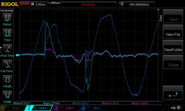 Light blue is the current transformer, 10V/div and 0.095 V/Amp The negative going peak is 30V which is 315 Amps. The DC bulk capacitor on the HV side of this PS seems to appear as a short circuit during the initial stage of charging. The Purple trace is as always the 50 Amp LEM current sensor. Blue is AC output voltage. These short lived high current events show how important it is to over build the mosfets. This inverter under test uses 4 x IRF3808 on each leg of the bridge These are rated at 140A each at 25 Deg C for continuous load. Pulse current rating is 550 A and I guess this is the max current you can put through the device while being careful not to let the chip get "too hot" wronger than a phone book full of wrong phone numbers |
||||
| poida Guru Joined: 02/02/2017 Location: AustraliaPosts: 1476 |
Part 19: examining EG8010 pulse width modulation Today I show what I have found when looking at the measured PWM duty cycle of an EG8010 based inverter board. I wanted to look at the shape of the PWM duty cycle during a 50Hz cycle and maybe see if it differs from a sine wave. My prototype inverter, driven by an Arduino running custom software used PWM duty cycles based purely on the value of a sine curve at the required angles. With a 20Khz PWM base frequency, this leaves 200 individual PWM cycles to modulate. I was wondering if the EG8010 was doing any special voodoo with the PWM duty cycle or just plain sine function based modulation. First I obtained a complete 50Hz (plus a bit) output AC waveform as well as the low side 20Khz mosfet gate drive signal. The DSO I have has ample memory for this and I ended up with 3M samples of these 2 channels, plus DC current and primary winding current. The sample rate was 150 M samples /second. This is almost too much data. A bit of VB.net code gave me a nice .csv file to import into Excel. I resampled the 150Msamples /sec data down to only 10,000 samples to keep it reasonable for Excel. Dark Blue is AC output voltage, It is higher magnitude to allow a clear view of the other 2 curves. The Excel file lets you tune it so they all line up. Green is a pure sine wave, aligned with AC output Purple is calculated PWM duty cycle (i.e. counts of samples of the gate drive when it is > 8V) 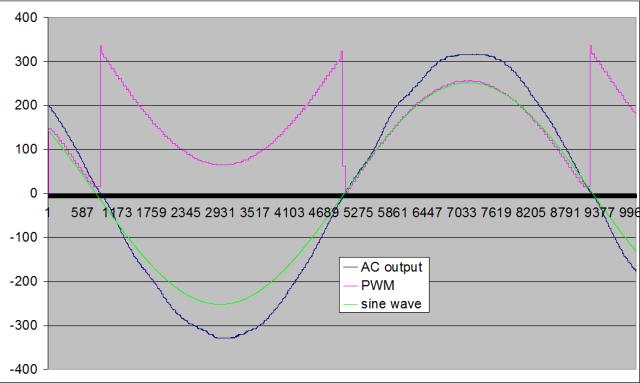 So it seems to me the EG8010 is using PWM duty cycle almost exactly the same as a sine wave. There you go. I was always wondering what EG used and now we know. I was hoping to maybe see some trickery (i.e. modification to sine wave) in the EG8010 PWM that might be the cause of the wobbles in AC output seen immediately after AC output voltage crosses zero. But no. This means the wobbles are electronic of origin and my idea that these wobbles are due to the injection of very high frequency pulses into the primary remains the best explanation. I attach the excel file if you want a look at it. 2018-04-13_152659_pwm.zip wronger than a phone book full of wrong phone numbers |
||||
| tinyt Guru Joined: 12/11/2017 Location: United StatesPosts: 559 |
Very nice poida. This is just a guess - Maybe the wobbles are due to the non-linearity of the magnetics, specially at 20KHz. |
||||
| Madness Guru Joined: 08/10/2011 Location: AustraliaPosts: 2498 |
You really get into the nitty gritty of it Poida, well done. My observations of wobbles and spikes at 0 crossing are the wobbles are the result of incorrect value choke. 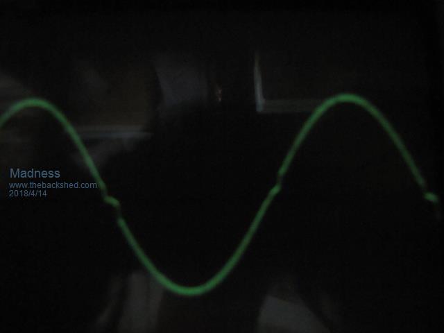 Sharp spikes that I experienced were from the MOSFET drive not being up to driving the number of MOSFETs I was using. Also a out of spec MOSFET could cause spikes. Since I started using Totem pole transistors to drive the MOSFETs and a different supplier of MOSFETs this problem has not come up again. I am waiting on some IR2010 driver chips to arrive to see if they make any difference compared to the IR2110s. 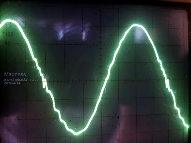 There are only 10 types of people in the world: those who understand binary, and those who don't. |
||||
| Warpspeed Guru Joined: 09/08/2007 Location: AustraliaPosts: 4406 |
Poida, generating a PWM sine wave directly from a lookup table is fairly straightforward. What makes it much more complicated is continuously adjusting (regulating) the output voltage, and in some cases programming the output frequency up and down as well. Its not difficult in theory to adjust the amplitude up and down, its just simple multiplication. The real difficulty is getting conventional software to do it fast enough in real time with fine enough time resolution for high frequency PWM. The way I have done this myself long ago, was to use a dual port ram. A basic microcontroller can do all the required number crunching, working as fast as it can go, and continuously modifies and updates a sine wave stored in a dual port ram, which is then used as a lookup table template for one complete mains cycle. The bits stored in the ram can then be read out at a much higher speed from the second "output" port of the ram. This can produce high frequency PWM directly, using just a continuously clocked counter and a magnitude comparator. The counter clocking speed could be made variable to give a varying output sine wave frequency if that is a requirement. The dual port ram effectively isolates the software side from the much faster hardware driven output side. The microcontroller can chug along relatively slowly and continuously update the amplitude of the stored sine wave byte by byte completely asynchronously, and it can do that without any timing constraints. All sorts of goodies like PID control, and soft start can then readily be written into the software. The EG chip is probably some kind of common commercial FPGA chip that works in a similar way to the above, in that the various internal functions are pipelined, with several things happening simultaneously and at different speeds. Its the only way that I can see to get both the high speed and the very fine time resolution and include quite a few nice features all in a single low cost chip. Cheers, ĀTony. |
||||
| noneyabussiness Guru Joined: 31/07/2017 Location: AustraliaPosts: 527 |
Warp, i can relate, i wrote a basic spwm program in arduino and the biggest drama was getting the adc to read and spit out the adjustments to he next cycle in short enough time.. it did it i guess but it was pushing it..( probably my lack of programming skills didnt help ether) , Poida has done a far better job, and its so interesting reading his adventures. . Im going to write up a review but i have a " PJ on roids " that i purchased about 6 months ago (different manufacturer) and its been fantastic. . It uses 2 micros, probably along the lines of what you mentioned above.. I think it works !! |
||||
| noneyabussiness Guru Joined: 31/07/2017 Location: AustraliaPosts: 527 |
link to program If anyone interested, and want to contribute ... bit of fun I think it works !! |
||||
| Warpspeed Guru Joined: 09/08/2007 Location: AustraliaPosts: 4406 |
I have been messing with PWM inverters, class D amplifiers, multi step inverters, and variable frequency drives for years. Its an absolutely fascinating subject. There are some much better, nicer, and faster microcontrollers around now than there were thirty years ago. But its still a pretty stiff challenge only for the very brave. Maybe we should start a new thread rather than hijacking this one ? I have experimented with some original and off beat ideas with great success that may spur further thought and development from others here. Putting together something right now in fact. Willing to share, and would particularly value the ideas and experiences of others. Cheers, ĀTony. |
||||
| Clockmanfr Guru Joined: 23/10/2015 Location: FrancePosts: 437 |
Hi Tony, Warpspeed, As usual, yet another very nicely put, a good post !!!!. Everything is possible, just give me time. 3 HughP's 3.7m Wind T's (14 years). 5kW PV on 3 Trackers, (10 yrs). 21kW PV AC coupled SH GTI's. OzInverter created Grid. 1300ah 48v. |
||||
| tinyt Guru Joined: 12/11/2017 Location: United StatesPosts: 559 |
A new thread would be nice. In my experimental inverter schematic, I have made provisions to use an arduino nano and added a net (G0XING) to sync the generated sine wave with the grid. I don't know if the atmel chip can do it. It was a 'just-in-case'. |
||||
| poida Guru Joined: 02/02/2017 Location: AustraliaPosts: 1476 |
Part 20: where the wobbles come from I am continuing in my investigation of causes of AC output waveform distortion. I assume we all have a clear understanding of PWM synthesis of a sine curve. Skip all this if you know all about synthesis of the waveform, else read on if interested. 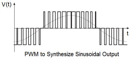 It's important to note that the sine wave is continuous, that is, it has a value at any and all points in time. PWM, or the duty cycle of the PWM has discrete values at any and all points in time. It's ON or OFF. No PWM duty cycle implies zero duty cycle (i.e approximating a zero level of a waveform) but it can also represent an absent waveform or signal too. There is no way to produce a continuous waveform via PWM (except in the special case of DC which is not important to this discussion). We can produce a waveform that is progressively more accurately approximating the continuous curve as we increase the PWM frequency. This is akin to increasing the sample rate of a sampled continuous signal. In the case of the EG8010 based inverter the PWM frequency is 23.4 kHz. My Arduino prototype produces a 20kHz PWM output. I can also make it produce any other frequency such as 10kHz or 40kHz PWM sine wave modulated output. Different PWM frequencies was one of the reasons why I built the prototype. These inverters we are building and playing with use PWM to approximate a continuous sine wave. The deficiencies of the PWM approximation are smoothed over by the filtering of the PWM output as it is fed into the transformer. The filter we use is a LC type low pass filter. The L part is the 45uH (or whatever) inductor and the C part is the mains voltage capacitor across the 240V AC output. This filter arrangement passes low frequencies through with very little resistance and progressively reduces high frequencyÆs power. where Low frequencies such as 50Hz. and High frequencies such as > 100 Hz We design the filter to efficiently pass the 50Hz output. No filter is perfect and so this simple LC filter lets through some amounts of the various higher frequencies. Finally I want to bring up the frequency components of a waveform. A sine wave without very much of any other frequencies will have a power spectrum of a single high value at one frequency and low values of power at all the others. sine wave 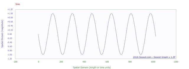 fft (or graph of power v/s frequency) of sine wave 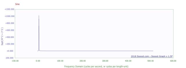 See the peak of about 1000 at the location on the X axis = 1? That is showing that all the power of the sine wave is contained in one frequency. A pulse waveform is a very different fish indeed. pulse 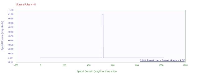 fft of pulse 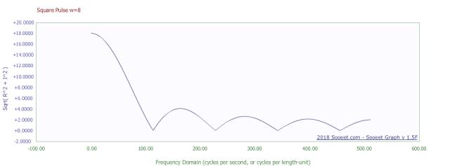 See that there are a lot of frequencies that carry significant power levels in this pulse waveform. PWM is nothing more than a sequence of pulses. The high frequencies are the result of the fast changes in the signal. We are generating signals with large amounts of high frequency power within the PWM output of the inverterÆs power bridge. The PWM is to all intents and purposes a square wave with fast edges (the rise and fall of the square wave). We are pumping into the transformer primary a huge amount of high frequency power. Here in this forum we have seen various peopleÆs inverter AC waveforms, containing various wobbles. here These wobbles are in my view caused by the PWMÆs imperfect approximation to a continuous sine wave and the filter. The degree of wobble and the frequencies found within the wobbles are related to the LC filterÆs frequency attenuation characteristics. I show a simple experiment, what happens to the AC output waveform when you purposely introduce more high frequency power. In this experiment no changes were made to anything other than modifying the PWM data in the following way: Blue is unchanged sine wave Red is the modified sine wave similar to what I used belowģ 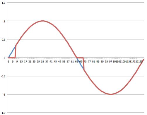 I zeroed the first 10 of 200 values of the sine wave PWM lookup table in the Arduino code. This effectively adds a fast change to the PWM approximated sine wave, thereby adding some more HF power. dark blue is AC output light blue is primary winding current. unaltered PWM 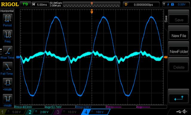 zeroed 10 of 200 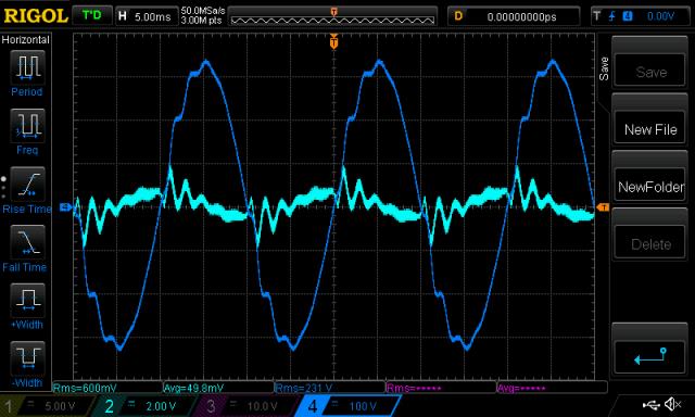 Clearly these wobbles in the AC output are due to incomplete removal of high frequency power which is generated by PWM sine wave synthesis. It looks like I added a fair bit of power at about 1/2ms or 500Hz by adulterating the PWM lookup data. Notice that in each of our inverter AC output traces, the wobbles begin after the AC output passes through zero? This is when the PWM is zero and the first short pulse (approximating a small value of the sine wave and so it MUST BE SHORT) happens about 50 us afterwards. We have seen (above) the power at various frequencies that is contained in a pulse signal. wronger than a phone book full of wrong phone numbers |
||||
| Warpspeed Guru Joined: 09/08/2007 Location: AustraliaPosts: 4406 |
The big problem with PWM is that the high frequency switching frequency (and its odd harmonics) need to be removed, to recover the desired 50Hz pure sine wave power buried underneath. This obviously requires some low pass filtering. Now here we must introduce some reactive components, both inductive and capacitive to achieve the low pass filtering effect. Some of these components are deliberately introduced and obvious, and others are hidden and less obvious in that they represent stray inductances and stray capacitances due to construction and layout. Designing an efficient low pass filter is fairly straightforward, as long as you can define the EXACT source and load impedances. The problem with an inverter is that there is NO WAY to define the load impedance. There is no way to anticipate what may be connected as a load. It can vary between a complete open circuit, to a very low pure resistance, to crazy non linear loads that switch on and off at various points in the cycle, and highly inductive or capacitive loads of very low power factor. So we have a big toroidal transformer that may typically have a self resonance of a few Khz, due to the very high inductance of the secondary winding, and capacitance back to the metal in the core and between turns. Then we add a series choke in the primary that will add another self resonance. And maybe even more LC filtering after that. Then we fire up the inverter, and wonder why the output waveform has some wobbles and discontinuities on it. Kind of like a jelly in an earthquake, it will wobble around according to its own self resonant nature, pretty much unpredictably. If you load the bastard right down with a heavy purely resistive load, it will probably work fine and produce a nice clean sine wave. But the real world loads are not often perfectly linear or resistive, and you are very likely going to see some kinks, wobbles, and strange weirdo output waveforms. Trying to make an efficient low pass filter that will work into absolutely any kind of extreme load is an exercise in futility. But in practice the grid waveform is pretty crappy and distorted anyway, so why worry ? All your "stuff" is very likely to work perfectly well on a wobbly 230v waveform. Cheers, ĀTony. |
||||
| noneyabussiness Guru Joined: 31/07/2017 Location: AustraliaPosts: 527 |
Always a interesting read poida, please keep it up... its so fascinating. Us not so bright ones are really enjoying each saga I think it works !! |
||||
| Clockmanfr Guru Joined: 23/10/2015 Location: FrancePosts: 437 |
Plus 1 on the, "not so bright ones". Warpspeed, yes I agree. Until the OzInverter is under some sort of loading then wobbles in the waveform are something I can live with. I am concerned that just testing certain parts may not necessarily be such a good idea and could cause faults at later stages in the build. I am definitely a 'Oztules' Fan of 'follow known procedure, check everything, assemble everything, charge the big caps on power up, and switch on'. It seems to work for me.! interestingly, on first loading of a virgin toroid and virgin choke, both make a peculiar vibrating low frequency audible sound. 5 minutes later after a bit of loading, even a 100 watt light bulb for idle power use, the Ozinverter settles down to a very gentle quite hum!. Switched off and back on the OzInverter never makes that original virgin start up sound. Everything is possible, just give me time. 3 HughP's 3.7m Wind T's (14 years). 5kW PV on 3 Trackers, (10 yrs). 21kW PV AC coupled SH GTI's. OzInverter created Grid. 1300ah 48v. |
||||
| Tinker Guru Joined: 07/11/2007 Location: AustraliaPosts: 1904 |
I recently sold my old 1.8KW Latronics LF inverter (it was 24V version) but before the buyer came I looked at its waveform with my little kit oscilloscope and a 1200W load (fan heater) on the inverter. Its output was pretty wobbly, a fair bit worse than the output of my home built 3KW inverter with the same load. My inverter showed little difference from the idle wave form, which I think is pretty good. So, this commercial unit is not perfect either. Klaus |
||||
| Warpspeed Guru Joined: 09/08/2007 Location: AustraliaPosts: 4406 |
Its really an unavoidable problem, and wobbles or freedom from wobbles seems to be more a combination of lucky coincidences than anything else. Stray resonances are always going to be there somewhere, they just may not see enough energy at the specific frequency to be provoked into action. Unipolar drive may have something to do with this as well. One side of the transformer is being driven with a 50Hz square wave, and that will be pretty rich in odd harmonics. So if there is an unlucky resonance at a few hundred Hz that coincide with one of those harmonics, that might be enough to set it off. That is all just a theory.... With bipolar drive, both sides of the bridge see high frequency PWM, and the only low frequency energy will be at 50Hz. And because its a 50Hz sine wave, there should be no significant harmonics of 50Hz present at the transformer. In fact it should be pretty clean right up to the PWM switching frequency. I have never tried comparing unipolar PWM drive to bipolar PWM drive as far as the effects on any kinks or wobbles. It might be something to try one day. Some of the driver boards have a link to select either mode of operation.h My own multistep inverter has a very good sine wave shape, but with a very small amplitude ripple all over it everywhere. Total harmonic distortion unfiltered is less than 1.5% so its not too bad. I have tried many times to filter that out, but every filter I have tried so far brings up wobbles and self resonances that actually make things worse than without any filtering at all. With high frequency PWM there absolutely must be some output filtering, and that is the problem. Cheers, ĀTony. |
||||
| The Back Shed's forum code is written, and hosted, in Australia. | © JAQ Software 2026 |
