
|
|
Forum Index : Microcontroller and PC projects : Armmite L4: MM2 compatible PCB
| Author | Message | ||||
| matherp Guru Joined: 11/12/2012 Location: United KingdomPosts: 11514 |
This little PCB will plug into a standard 28-pin DIP socket exactly like a MM2. The difference is that it has on board an Armmite L4 with in-built RTC and also a 16Mbyte Flash drive for storing programs and data using the Armmite's Flash file manager and, of course, it can run at ultra-low power consumption. The pinout is arranged so that most special function pins are in the same place as the MM2: I2C, SPI, COM1, console, PWM1A, 1B, 2A. The Armmite has on on-board DAC and second SPI channel but does not currently support COM2, PWM1C or PWM2B on the MM2 pins. If this PCB is useful I can modify the Armmite firmware so that you can, optionally, use the same pin numbers as the MM2 and therefore most programs would run without any change. The PCB is just 37 x 20 mm. Soldering itB will require a heat gun as the Armmite chip is a 32-pin QFN and the clock crystal is also a bit tricky. Otherwise all components are 1206 so very easy to solder. The 28-pins on the underside of the PCB are surface mount and at standard 0.3" spacing between rows. 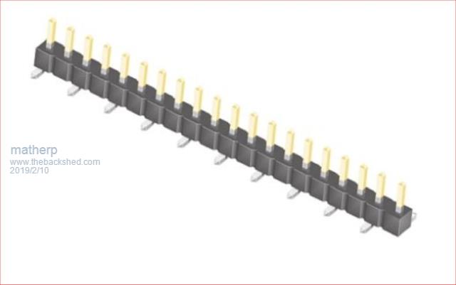 The Armmite has the advantage that it has a built-in bootloader so the MMBasic firmware can be loaded using the console connection by making the "load" jumper. Then it can be set to "run" for normal use. 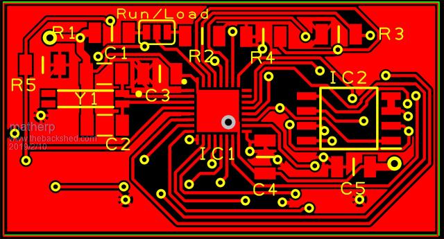 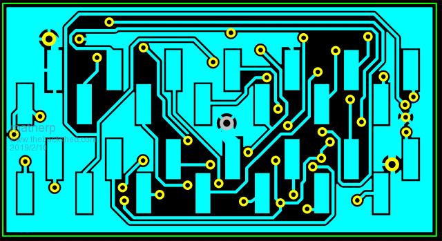 Schematic: 2019-02-10_055940_ARMdip_-_Project.pdf |
||||
| viscomjim Guru Joined: 08/01/2014 Location: United StatesPosts: 925 |
This is an extremely awesome idea! You never cease to amaze. I am starting to love the low power stuff now playing with solar and some li ion stuff. Appreciate the effort!!! |
||||
Quazee137 Guru Joined: 07/08/2016 Location: United StatesPosts: 603 |
Can the dac be jumpered to MM2's pin 20 the 47uF cap? Easy enough to pull cap and add a wire to use the dac. And a MMBasic way to make use of the dac. Would this fit in between the TFT and board on the backpack? Also is this MM2, MM+ or MMX code compatible. |
||||
| matherp Guru Joined: 11/12/2012 Location: United KingdomPosts: 11514 |
The twin channel dac outputs are on MM2 pins 9 and 10 on the design. Dac output is already supported from Basic in the Armmite firmware. Don't know, sorry Mix of them. All normal MM2 Basic commands + some MMX/Armmite H7 features. No GUI and currently no touch but MM2 touch may be supported. The big plus over the MM2 is a full file system with all MM+/MMX commands but running on a flash chip rather than an SD card. I do need to do a manual - it is on the to-do list.  |
||||
lew247 Guru Joined: 23/12/2015 Location: United KingdomPosts: 1709 |
I must be going stupid in my old age. I can't see any 28 pin socket or pins on the board but more importantly, what exactly is an MM2? I know the MM, MM+, Picromite,Armite,Explore64, E100 but even though I can find references to code for the MM2 on the site here I can't find anything that says what it is |
||||
| matherp Guru Joined: 11/12/2012 Location: United KingdomPosts: 11514 |
The rectangular pads on the bottom (blue) are to solder the type of header shown in the first post that makes the pins MM2 is the latest version of the MM (normal 28-pin DIP). There was a version 1 Micromite based on the MX150 (before your time  ) ) |
||||
| Quazee137 Guru Joined: 07/08/2016 Location: United StatesPosts: 603 |
I really miss interpreted this line.  Ill need to get one or two and see if it will fit in between the TFT and the backpack board. I'd like to use these in place of the MM170's I'm using now as it frees me from using the external RTC/FRAM and makes for two I2C ports on my Quad pump boards. Giving me thoughts of adding Ph and conductivity by ways of ADS1115. Is the SPI fast enough to do the Advanced Graphics of MM+ ? That on a MM2 would be very very nice. Any Hat stand version possible? Been using 3.5" and 4" TFT's. Thanks for YOUR hard work. Now where is your [TIP] button. |
||||
| lizby Guru Joined: 17/05/2016 Location: United StatesPosts: 3784 |
MM2 touch with full (flash) file system would make for a powerful system--an MM2 upgrade at a comparable speed. PicoMite, Armmite F4, SensorKits, MMBasic Hardware, Games, etc. on FOTS |
||||
| matherp Guru Joined: 11/12/2012 Location: United KingdomPosts: 11514 |
Touch is actually trivially easy to implement in Basic. Basic interrupt for the IRQ pin and then read the XPT2046 registers function T.Getdata(command as integer) as integer 'get data from the touch controller local integer i,j,k pin(T_CS)=0 i=spi(command) j=spi(0) k=spi(0) pin(T_CS)=1 T.Getdata= (j*256+k)>>4 end function ' function T.getxy(x() as integer, y() as integer, timeout as integer, samples as integer) as integer local integer i timer=0 for i=0 to samples-1 do while timer<timeout and pin(T_IRQ)=1:loop if timer>=timeout then T.getxy=0 exit function else y(i)=T.getdata(&H90) x(i)=T.getdata(&HD0) endif next i T.getxy=1 end function |
||||
| lizby Guru Joined: 17/05/2016 Location: United StatesPosts: 3784 |
I guess I meant touch with an ILI9341 SPI display--is that supported at present? PicoMite, Armmite F4, SensorKits, MMBasic Hardware, Games, etc. on FOTS |
||||
| matherp Guru Joined: 11/12/2012 Location: United KingdomPosts: 11514 |
PCBs arrived today - one soldered and tested - all seems OK  The last picture show the module plugged into one of BigMik's Mup V3 replacing the MM2. The ARMdip PCB has onboard RTC, and Flash filesystem. The gerbers I used are attached 2019-02-28_002931_ARMdip.zip 2019-02-28_003053_ARMdip_-_Schematic.pdf 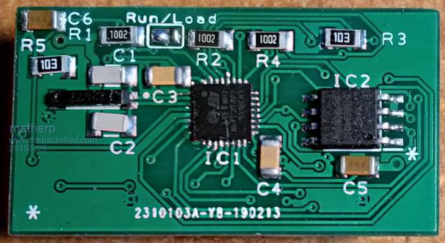 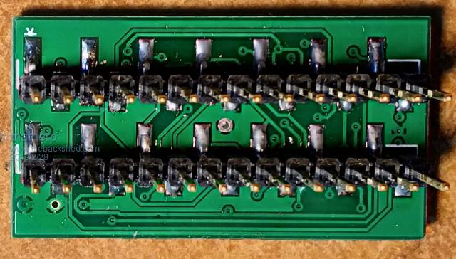 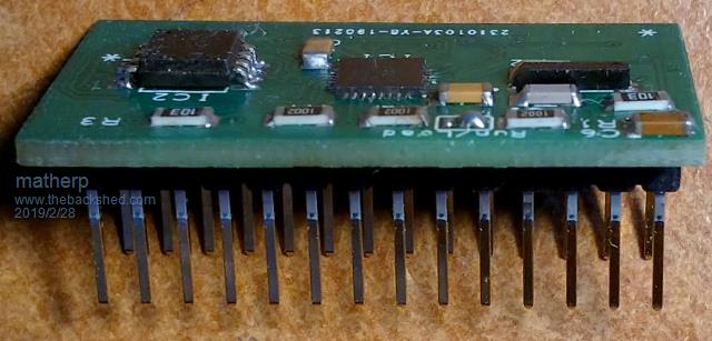 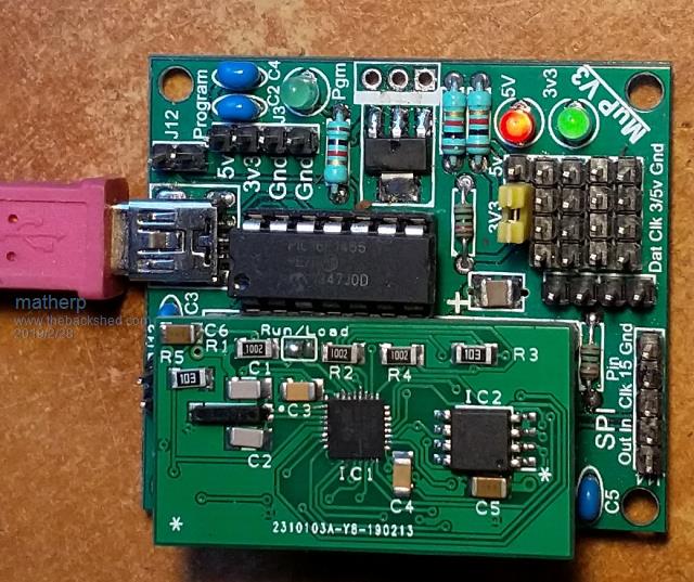 |
||||
| lizby Guru Joined: 17/05/2016 Location: United StatesPosts: 3784 |
Nice looking. If you put one on one of BigMik's MM2 backpacks, can it run an ILI9341 LCD or is that code not present? PicoMite, Armmite F4, SensorKits, MMBasic Hardware, Games, etc. on FOTS |
||||
| matherp Guru Joined: 11/12/2012 Location: United KingdomPosts: 11514 |
Forgot to explain. To load the Armmite L4 firmware you should connect a USB UART to the ARMdip as follows: UART RX to pin 11 (As per the MMBasic console) UART TX to pin 26 (NB not pin 12 which is normally used for the MMBasic console) Make the shorting link on the "LOAD" side Run STM32CubeProgrammer, set the com port to the USB UART, the baud rate to 115200 and the parity to even. Cycle the power on the ARMdip and then press connect and the STM32CubeProgrammer will connect to the STM32L432's bootloader. Then select the firmware to be downloaded (.bin or .hex) and start programming. Once the firmware is successfully installed move the shorting link to the "RUN" position and use the normal MM2 console pins for the USB/UART. No hardware programmer needed |
||||
| Quazee137 Guru Joined: 07/08/2016 Location: United StatesPosts: 603 |
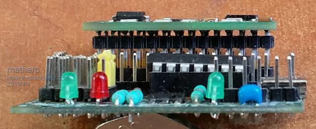
matherp That is very very nice for me as I brought out 26 to a 3 pin header om my quad relay controllers for possible ADC use. Could you please give us a side shot of the board plugged into MUP V3. That side profile would show its height as compared to a 170 I have in a MUP V3. That will answer my question of it fitting between TFT and pcb of 170 back packs board. Thanks again In a loop trying to get the ST software. I give e-mail read e-mail click in e-mail and repeat it will not just download |
||||
| matherp Guru Joined: 11/12/2012 Location: United KingdomPosts: 11514 |
 Note the header pins are available in various lengths (see the datasheet ). I'm using the 8.13mm version. |
||||
| Quazee137 Guru Joined: 07/08/2016 Location: United StatesPosts: 603 |
Thanks matherp it looks like I can solder the pins then remove the plastic part and flow a bit of epoxy to stabilize the pins and trim to fit. My other thought is to solder a 2mm thick SMD female to the board and pop some pins into the socket that will work with a batch of 20 of 2.8" that had the SD holder smashed and with your board I won't need the SD. It took five tries to get the STM32CubeProgrammer to download. But I got it.  |
||||
| The Back Shed's forum code is written, and hosted, in Australia. | © JAQ Software 2026 |
