
|
|
Forum Index : Microcontroller and PC projects : PicoMite VGA Edition - pcbs etc.
| Author | Message | ||||
| Mixtel90 Guru Joined: 05/10/2019 Location: United KingdomPosts: 8911 |
We live life on the edge (of the pcb), Grogster... ;) For all my working life, and most of my electronics hobby, I've almost always started with a schematic before considering a layout or pcb. That's because I enjoy schematics and am far less happy with the mechanical side (although laying out a chassis for a valve amplifier is still fun!). When I started with PCB design packages I found them to be the most stubborn, awkward, incomprehensible and devious pieces of software I'd ever used. On top of all that, the manuals were written by experts in the pcb field who knew all about making pcbs and were just showing how their particular package did things. There was very little for the beginner. Even now, the beginner's part of the manual tends to show how to make a simple pcb - but doesn't include odd shaped boards or boards with slots or non-through-plated holes in them. And have you attempted to read the KiCAD manual section about creating a new component? The beginner's section only ever uses library components - not the real world at all. I still don't like the pcb design packages, although I fully appreciate what they do and how useful they are (having finally managed to use a couple after a fashion). I only use one to get Gerber and drill files. (Just looked - Sprint Layout can't use netlists.) Edited 2021-12-26 19:26 by Mixtel90 Mick Zilog Inside! nascom.info for Nascom & Gemini Preliminary MMBasic docs & my PCB designs |
||||
| Kabron Regular Member Joined: 30/11/2017 Location: GermanyPosts: 65 |
PS/2 keyboard perfectly works with this simple schematic 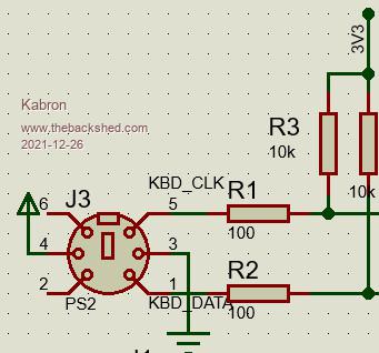 |
||||
| Mixtel90 Guru Joined: 05/10/2019 Location: United KingdomPosts: 8911 |
It'll work fine, but if the keyboard supply is 5V then you MUST clamp the inputs to a Pico to 3.3V as the keyboard might have its own pullups to its supply (some do, although they shouldn't) and the built-in esd protection diodes might cook. I would recommend increasing the 100R resistors to 270R and adding BAT85 schottky signal diodes from the Pico inputs to 3V3. I've had this running in simulation and the max voltage at the pin was about 3.45V, the max allowed is VDD+0.3V, i.e. 3.6V in this case. The input resistors should be as high as possible, as additional protection, but above 300R the Pico won't pull a TTL input below 0.5V if a 10k pullup is used at the keyboard end. This arrangement (with 220R or 270R input resistors) is shown on an application note for a 3.3V FPGA (sorry, I can't remember where I found it). Mick Zilog Inside! nascom.info for Nascom & Gemini Preliminary MMBasic docs & my PCB designs |
||||
Grogster Admin Group Joined: 31/12/2012 Location: New ZealandPosts: 9975 |
SL6 does have it's limits, I agree. But when I looked at other softwares, I was amazed at how convoluted they were, and how difficult it was to do simple things. Everything like simply drawing a track seemed to require several sub-menus of settings to be correct before you could. Not saying that is a BAD thing, per se', but I just PERSONALLY found it confusing and overly complicated. Then I found SL6. Extremely simple to do any boards up to four-layer. Certainly acknowledge that SL6 is not for everyone, but when it comes to PCB software, it seems very polarized as to what one designer will use, vs the other ones that other people will use. At the end of the day, I decided that what works for me - works for me, and looking at more advanced software that can do more, but sucks the blood out of your brain in the process, was not worth the effort. Each to their own, I guess. What I CAN say, is that I am delighted that you chose SL6, as I think it is a brilliant bit of CAD software IMHO. I agree with you on your reply to Kabron. Smoke makes things work. When the smoke gets out, it stops! |
||||
| Plasmamac Guru Joined: 31/01/2019 Location: GermanyPosts: 620 |
hi, what version should i use for jlc pcb ordering , or should i wait for anything new version? thx Plasma |
||||
| Mixtel90 Guru Joined: 05/10/2019 Location: United KingdomPosts: 8911 |
If you mean my mini version, then only the latest (PicoMiteVGA mini 12), Plasma. All the other versions of that definitely have errors. Of course, the latest might have errors too - it's just that no-one has built one yet to find them. :) If you carry on waiting I suspect that any changes will be very superficial now. I doubt if Peter will change any IO pins, for example. As far as I can tell it *should* work ok now, but I've not ordered any of the latest version boards myself yet. My main concern is that the cutouts in the end panels might not line up correctly. Note that in my Gerber files the end plates are NOT scored. That was to keep the price down to the minimum for the preliminary boards. I'm afraid it means a bit of awkward mechanical work to cut the board. I ordered five of the first version before I discovered that the PS/2 socket wiring is screwed up on that one so they will only be preliminary test rigs (although I might fix one up). I need something to check the case holes and practice my PCB scoring on anyway. Edited 2021-12-27 17:48 by Mixtel90 Mick Zilog Inside! nascom.info for Nascom & Gemini Preliminary MMBasic docs & my PCB designs |
||||
| Mixtel90 Guru Joined: 05/10/2019 Location: United KingdomPosts: 8911 |
Just playing with another possible version - see "Playing with Sprint Layout 6.0" thread. Mick Zilog Inside! nascom.info for Nascom & Gemini Preliminary MMBasic docs & my PCB designs |
||||
| Mixtel90 Guru Joined: 05/10/2019 Location: United KingdomPosts: 8911 |
This is the board for the original version 1.0, which has a wiring fault on the PS/2 socket. I might be able to sort that out. Now I'm going to experiment with putting V score lines between the end plates and the main board so that they can be snapped. I can see that process being a bit fiddly, but exact precision isn't needed in this case. I've now done a new version of this. This was a testing ground as it's the first time I'd used SL6 when ordering a board from JLC so I wasn't sure what would happen in some areas. I love the colour! :) 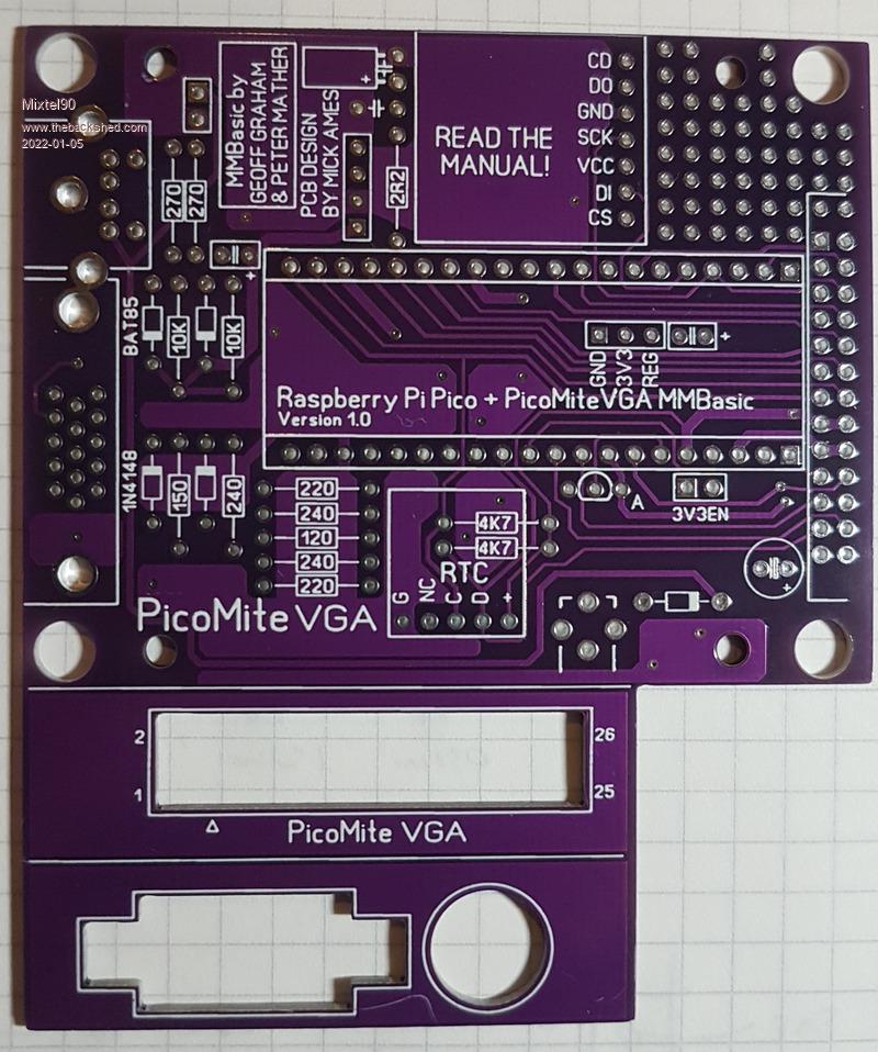 Mick Zilog Inside! nascom.info for Nascom & Gemini Preliminary MMBasic docs & my PCB designs |
||||
| Mixtel90 Guru Joined: 05/10/2019 Location: United KingdomPosts: 8911 |
Well, with tracks to the keyboard socket isolated and powered via USB it's working so I must have done something right. It also fits into the case. :) Now to finalise the latest version and build one of those. It has quite a few enhancements, but is more of a pig to get into the case... 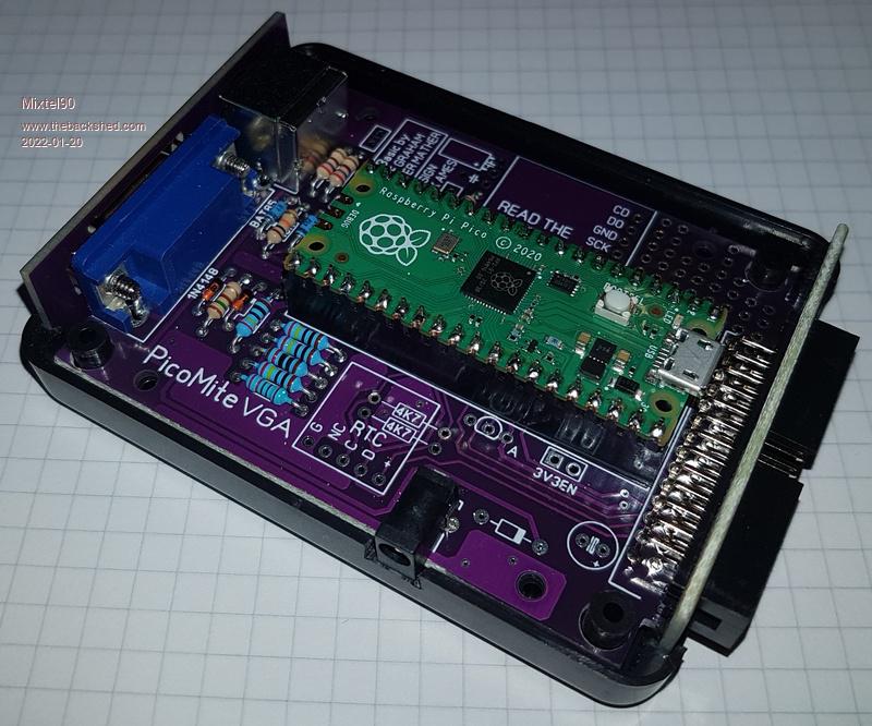 . Mick Zilog Inside! nascom.info for Nascom & Gemini Preliminary MMBasic docs & my PCB designs |
||||
| The Back Shed's forum code is written, and hosted, in Australia. | © JAQ Software 2026 |
