
|
|
Forum Index : Microcontroller and PC projects : Stamps
| Author | Message | ||||
| Mixtel90 Guru Joined: 05/10/2019 Location: United KingdomPosts: 8911 |
So what we need is a piggy-back board for a Pico that carries a uSDcard socket? I'll have a think.... The uSDsocket module I'm currently using can probably be (carefully) soldered directly over GND to GP13, having cut down the pins on it to 2mm-3mm. The VCC pin of the module would be cut off and a wire connected between it and the 3V3 pin of the PicoMite - via a 2R2 resistor if you are fussy. The module contains a capacitor of about 33uF and has 10k pullups on the control & data lines. It would make a plug-in PicoMite with it's own uSD on-board. The pins used are: Wire to 3V3 GP13 - CS GP14 - MOSI GP15 - SCK GP16 - MISO GND The uSDcard slot is over the top of GP18-GP21 so the card will project here. Edited 2022-03-31 21:06 by Mixtel90 Mick Zilog Inside! nascom.info for Nascom & Gemini Preliminary MMBasic docs & my PCB designs |
||||
| robert.rozee Guru Joined: 31/12/2012 Location: New ZealandPosts: 2528 |
the simplest approach would be to design a small PCB that sits over the top of an existing PICO board, and contains a microSD socket, reset button, and perhaps even a 3-terminal 3v3 linear regulator to replace that nasty switcher: 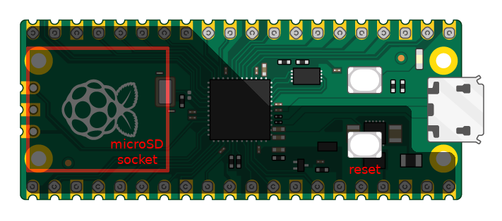 aside from the massive effort for little gain that peter mentions, the wearing out of the non-replaceable onboard flash would indeed be of major concern. far safer to not go there! cheers, rob � :-) Edited 2022-03-31 21:53 by robert.rozee |
||||
| Volhout Guru Joined: 05/03/2018 Location: NetherlandsPosts: 5931 |
Just the SD card socket. Don't over-complicate it (*). If you make the piggy back board so it exactly overlays on the pico IO pins, then you can place it flat on the pico board, and solder the header pins through 2 boards at a time. Only need to make sure to use pico pins for SD that do not interfere with VGA pins, so the piggy board can be used for all pico's. (*) reset and linear voltage regulator are only needed in limitted applications, end even then there are other work arounds (especially for the audio noise). Edited 2022-03-31 21:13 by Volhout PicomiteVGA PETSCII ROBOTS |
||||
| Mixtel90 Guru Joined: 05/10/2019 Location: United KingdomPosts: 8911 |
I've successfully soldered a SMD push button on top of pins 28 and 30. It just fits nicely and doesn't cause problems with pin 29. :) The pins that my uSDcard module uses don't clash with the VGA version. Edited 2022-03-31 21:14 by Mixtel90 Mick Zilog Inside! nascom.info for Nascom & Gemini Preliminary MMBasic docs & my PCB designs |
||||
| led-bloon Senior Member Joined: 21/12/2014 Location: AustraliaPosts: 209 |
@Grogster The only problem, I see, with the WS RP2040-Zero is components both sides of the board. Whereas the Seeed XIAO RP2040 components are all on one side but less GPIO. led Miss you George |
||||
| robert.rozee Guru Joined: 31/12/2012 Location: New ZealandPosts: 2528 |
i have little interest in VGA, a simple approach would be to have cuttable tracks underneath to select between VGA-avoiding pins and GP16-GP20 (incompatible with VGA). there is no cost to having pads for an AM1117 3v3 regulator, those who don't want to can simply not fit it. the same holds for a reset button (that i do use myself). the board would need to be spaced up slightly to clear existing components. remember, 3v3 needs to be picked up from pin 36, so the board needs to extend that far unless you use a flying wire. cheers, rob � :-) Edited 2022-03-31 22:13 by robert.rozee |
||||
| Tinine Guru Joined: 30/03/2016 Location: United KingdomPosts: 1646 |
So, yeah...all I/O is recognised on the Pimoroni PGA  Craig |
||||
| Mixtel90 Guru Joined: 05/10/2019 Location: United KingdomPosts: 8911 |
So, I screwed up on the GP numbers, but it works fine. It should be OPTION SDCARD GP13, GP11, GP12, GP10 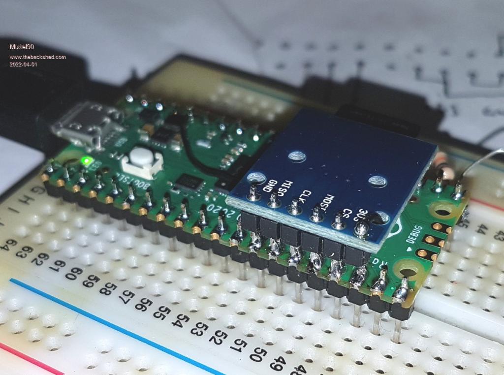 Mick Zilog Inside! nascom.info for Nascom & Gemini Preliminary MMBasic docs & my PCB designs |
||||
| led-bloon Senior Member Joined: 21/12/2014 Location: AustraliaPosts: 209 |
Not sure I see the logic here for a small PCB atop the Pico. 1. If you are running the Pico on a breadboard (and connecting and monitoring external devices via jumper wires), then, why not just connect an SDCard holder via jumper wires? 2. If you are intending to fit this on another PCB, why have this mini-PCB at all? 3. If you are intending to run the Pico just on it's own, then, what are you measuring that requires files on an SDCard? un-enlightened led (pun intended!) Miss you George |
||||
| hitsware2 Guru Joined: 03/08/2019 Location: United StatesPosts: 738 |
https://www.sparkfun.com/products/17745 my site |
||||
| robert.rozee Guru Joined: 31/12/2012 Location: New ZealandPosts: 2528 |
i'd forgotten that the SPI for the SD card was now bitbanged i've ordered a handful of those little boards from ebay. for my user case, i'll mount it over pins 23-28, socket-side up, with the 3v3 trace cut and routed up to pin 36.LED: a small daughterboard would suit those who want to get the SD card 'out of the way', much as was the case with the Explore-64 module. having the socket onboard is just one less thing to worry about when juggling wires on a solderless breadboard, or (shock, horror) building up a project on veroboard. but, as Mick has demonstrated, there is a similar solution already available ready-made. cheers, rob :-) |
||||
Grogster Admin Group Joined: 31/12/2012 Location: New ZealandPosts: 9975 |
@ hitsware2: Nice idea, but $19.50 - yikes. Getting a bit far away from the Pico module's $6 sweet-spot, just to get an SD card on-board. @ led-bloon: Agree with all your points there. Smoke makes things work. When the smoke gets out, it stops! |
||||
| phil99 Guru Joined: 11/02/2018 Location: AustraliaPosts: 3291 |
At the beginning of the PicoMite story someone glued a surface mount uSD socket on the raspberry logo, with thin enameled wire soldered to the pins. It would have been a bit fiddly to do but compact and cheap. |
||||
| Mixtel90 Guru Joined: 05/10/2019 Location: United KingdomPosts: 8911 |
@led I agree, but I'm sure there must be a reason otherwise there wouldn't be any sale for them. :) Mick Zilog Inside! nascom.info for Nascom & Gemini Preliminary MMBasic docs & my PCB designs |
||||
| led-bloon Senior Member Joined: 21/12/2014 Location: AustraliaPosts: 209 |
Still no enlightenment at the end of the tunnel! But knock your socks off! If it keeps you off the streets and out of trouble, I'm all for it (just not for me) led  Miss you George |
||||
| Mixtel90 Guru Joined: 05/10/2019 Location: United KingdomPosts: 8911 |
I'll let you know if this one comes in handy. :) I suppose they might if you had to save on PCB area. uSDcard holders are a pig to solder but they are the only size that will fit underneath a Pico to save space. Mick Zilog Inside! nascom.info for Nascom & Gemini Preliminary MMBasic docs & my PCB designs |
||||
| JohnS Guru Joined: 18/11/2011 Location: United KingdomPosts: 4335 |
For the Seeed XIA RP2040, the schematic looks to be  I think the 5.1K resistors on CC1 & CC2 mean it's used for charging. So, shouldn't communicate on USB D+ & D- ? John |
||||
| led-bloon Senior Member Joined: 21/12/2014 Location: AustraliaPosts: 209 |
@JohnS Not sure what your question is here, but... Sparkfun Pro Micro, Pimoroni TINY, Adafruit QT Pi, Seeed XIAO All boards have run PicoMite V5.07.03 without a problem (apart from all having fewer GPIO available) As mentioned previously, the Seed XIAO is running PicoMiteVGA (GPIO pin modified V5.07.04b8) with an SDCard attached too - no problems. led Edited 2022-04-02 13:11 by led-bloon Miss you George |
||||
| JohnS Guru Joined: 18/11/2011 Location: United KingdomPosts: 4335 |
I meant that because it claims to be just a charger (I think) it is not allowed to communicate over USB D+ & D- and so USB-related PicoMite features would not be allowed. They will in practice perhaps work - or will they? Might depend what USB cable is used? Maybe need to avoid a USB-C host? USB-C is such a confusing pile of stuff that I'm unsure if I've followed it correctly. John |
||||
| The Back Shed's forum code is written, and hosted, in Australia. | © JAQ Software 2026 |
