
|
|
Forum Index : Microcontroller and PC projects : PicoMite: I2C issues....
| Author | Message | ||||
Grogster Admin Group Joined: 31/12/2012 Location: New ZealandPosts: 9975 |
Hello.  I still consider myself a novice where I2C is concerned, so I may well be doing something obviously wrong. However, when I setup I2C, when I try to send a byte to an I2C slave, all that is ever sent, APPEARS to be the address byte. 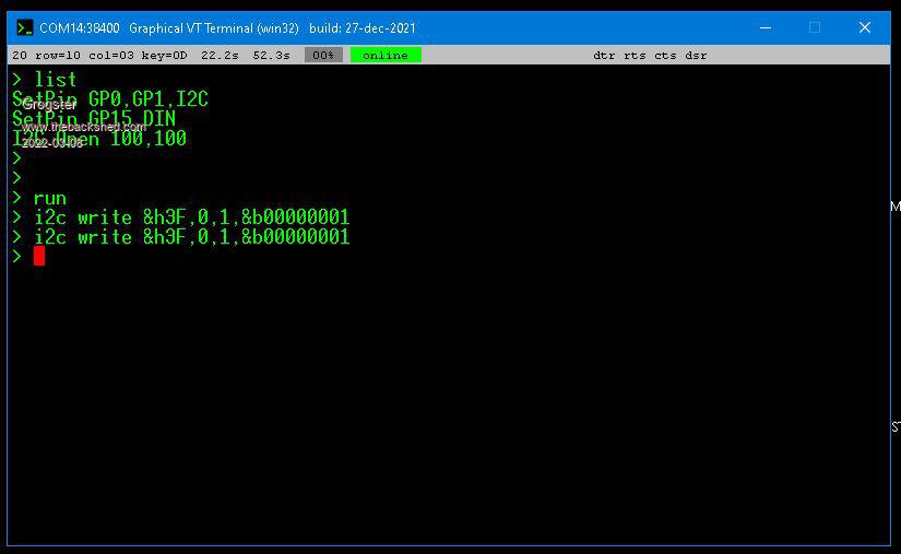 My simple testing code. Set the IC2 pins, open the port. At the command prompt, I am then experimenting - should I not be doing THIS perhaps? IE: All I2C commands need to be inside the code? Anyway, on to the next image: 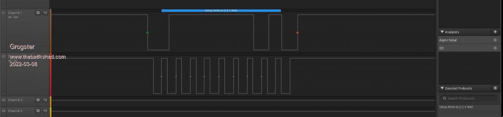 The logic analyzer on the GP0 and GP1 I/O pins only seems to reflect ONE byte, even though I am trying to send TECHNICALLY two bytes - the address and the data byte. I did not think you needed to count the address byte as part of the payload. Do I have that wrong? EDIT: Image is a little fuzzy - White-on-blue decoder info says "Setup Write to (~) + NAK" Parenthesis uses instead of square brackets, as they are forum formatting flags, but they are square brackets in the image. I tried that also here: 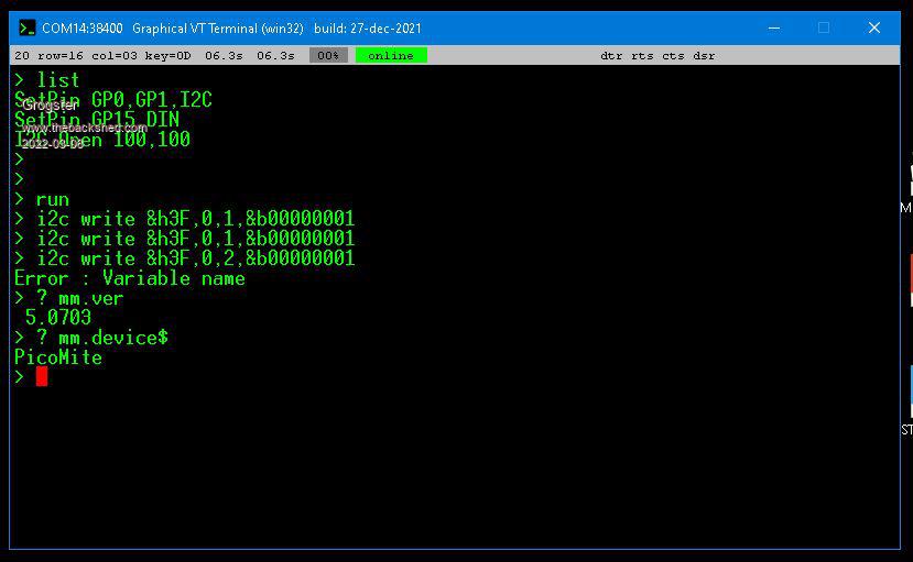 ....but I got an error message(Variable name), which suggests that what I was doing originally was correct in terms of command formatting. If I ? MM.I2C, it replies with 1 - NACK. The I2C slave address IS correct according to the manual. PCF8574 I2C port expander.pdf Page 3 of the PDF states that you only need to send two bytes - the address first, and the port bit-setting next. Page 7 states that only two bytes are needed for complete device programming. Page 4 states that with A0,A1 and A2 high(which they are), the slave address for this device should be &h3F Any ideas of what I am doing wrong? Do we perhaps have a bug in the I2C routines? I would have expected to see TWO bytes in the logic analyzer capture, but we only see one - and it's the wrong slave address..... Help!  Edited 2022-03-08 19:24 by Grogster Smoke makes things work. When the smoke gets out, it stops! |
||||
| matherp Guru Joined: 11/12/2012 Location: United KingdomPosts: 11514 |
Check mm.i2c. You are almost certainly getting a timeout. i.e. the Picomite isn't seeing the ack from the slave so times out rather than sending the second byte. |
||||
| Grogster Admin Group Joined: 31/12/2012 Location: New ZealandPosts: 9975 |
OK, will check that and post back. I2C pullups on this module are 10k, which seems a little high? I thought 4k7 was pretty much the standard for any I2C slave.... Smoke makes things work. When the smoke gets out, it stops! |
||||
| Grogster Admin Group Joined: 31/12/2012 Location: New ZealandPosts: 9975 |
Increased timeout to 250, EXACTLY the same response. Can someone confirm that the logic analyzer output IS the correct address? As it seems that the address byte is all that is ever being sent. I could believe that, if the slave never acknowledges.... But I want to know if the logic analyzer output is indeed a byte of 3F. 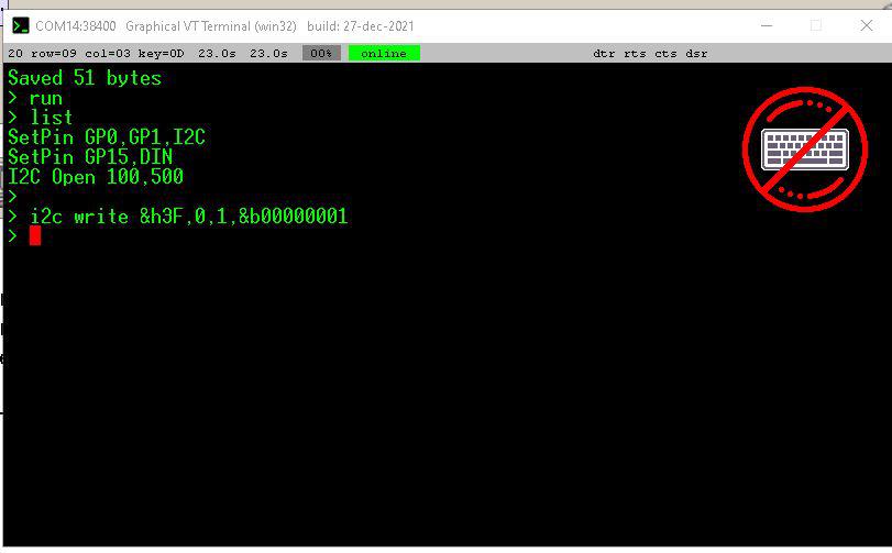 EDIT: Increased the timeout to 500mS - still exactly the same. It's like the slave chip simply isn't responding at all. I still need confirmation of the address byte as being 3F.... Edited 2022-03-08 19:53 by Grogster Smoke makes things work. When the smoke gets out, it stops! |
||||
| matherp Guru Joined: 11/12/2012 Location: United KingdomPosts: 11514 |
run the attached - what does it give |
||||
| Volhout Guru Joined: 05/03/2018 Location: NetherlandsPosts: 5931 |
Note there exists a pcf8574 and a pcf8574A. Both have different i2c adress ranges, so they can be used to create 128 io bits. PicomiteVGA PETSCII ROBOTS |
||||
disco4now Guru Joined: 18/12/2014 Location: AustraliaPosts: 1127 |
Hi Grogster, I have posted some code I used some time ago in the thread below. It had the address as &H40. by default. i.e. no solder blobs on the address selection pins. dim integer PCA9685_ADDRESS = &H40 'default &H40 (&H40-&H7F) See this for some example code Gerry F4 H7FotSF4xGT |
||||
| Volhout Guru Joined: 05/03/2018 Location: NetherlandsPosts: 5931 |
Check what chip you have! 8574 Or 8574A These have different adresses PicomiteVGA PETSCII ROBOTS |
||||
| Grogster Admin Group Joined: 31/12/2012 Location: New ZealandPosts: 9975 |
Hi chums. @ matherp: Results: 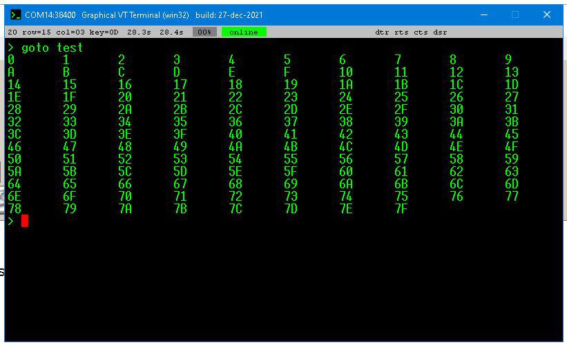 Not sure if that is what you were hoping to see. @ Volhout: This chip is a PCF8574T Not sure if that matters. PDF does not mention anything at all about the suffix and what it is. PDF DOES state it is for the A variant though, so perhaps there is another PDF for the non-A suffix part? @ disco4now: Thanks, I will check out your example code. I found another PDF from NXP this one, instead of Texas Instruments, and the NXP one has much more technical information in it, so I am reading this PDF now... PCF8574 I2C port expander(NXP).pdf Page 5 of THIS PDF gives read, write and 7-bit addresses(without the R/W bit), so it is suggesting that with A0,A1,A2 all high, the slave address is &H27 - totally different to what the TE PDF says for the same part. Confusing.  I will try with an address of &H27 and see if we get talkies. Smoke makes things work. When the smoke gets out, it stops! |
||||
| Grogster Admin Group Joined: 31/12/2012 Location: New ZealandPosts: 9975 |
WORKING!   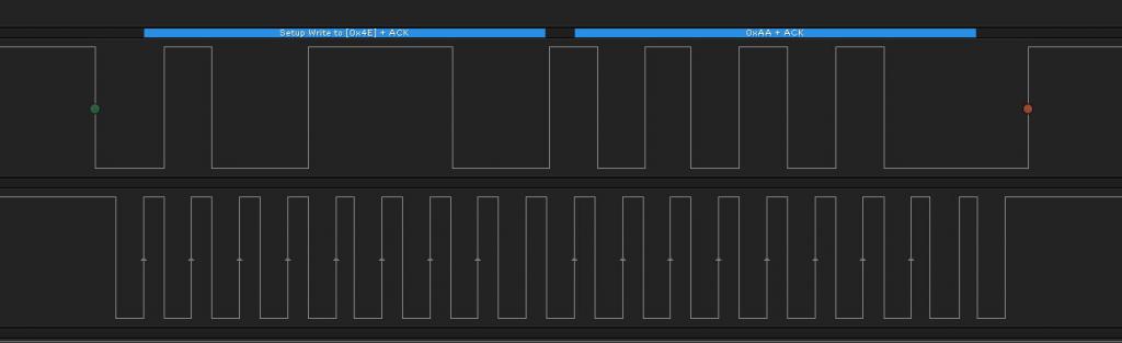 Slave address(7-bit) is indeed &h27. EDIT: The NXP datasheet is FAR superior to the TE one. The TE one only gives you very minimal information, really. As soon as a downloaded and started reading the NXP one, I could immediately see some new things to try, prompted by Volhout mentioning there are two different slave address ranges for this chip, depending on which one you have. The TE one only talks about the A variant and not the non-A variant, so no wonder I could not make it work, as I had no idea at all, that there could be another variant with a different slave address range....  Edited 2022-03-09 08:50 by Grogster Smoke makes things work. When the smoke gets out, it stops! |
||||
| Volhout Guru Joined: 05/03/2018 Location: NetherlandsPosts: 5931 |
Hi Grogster, PCF8574@TI You simply looked at the wrong datasheet. TI has separate datasheets for the 8574 and 8574A NXP has a combined datasheet I only could help you since I (myself) had the same problem years ago.... Volhout PicomiteVGA PETSCII ROBOTS |
||||
| Grogster Admin Group Joined: 31/12/2012 Location: New ZealandPosts: 9975 |
Thanks anyway, Volhout. I much prefer a single datahsheet that covers all variants such as the NXP one. If TE want separate datasheets, it would be nice to mention in BOTH of them, about the existence of the other variant and why, then I would have gone looking for the non-A PDF, but they did not, which is why I thought I HAD the one and only datasheet. Hey-ho. Everything is working now that we have established the correct slave address.  Smoke makes things work. When the smoke gets out, it stops! |
||||
| lizby Guru Joined: 17/05/2016 Location: United StatesPosts: 3784 |
Thanks, Grogs. Here are two PCF8574s toggling LEDs: PCF8574 output to LEDs Dim integer k1=&b10101010,k2=&b01010101 Do �I2C write &h38,0,1,k1: I2C write &h39,0,1,k2: Pause 500 �I2C write &h38,0,1,k2: I2C write &h39,0,1,k1: Pause 500 �If Inkey$<>"" Then Exit Loop I2C write &h38,0,1,255: I2C write &h39,0,1,255 ' turn off FCF8574s use negative logic, so writing a "1" turns a bit off and writing a "0" turns it on. ~ Edited 2022-08-22 00:44 by lizby PicoMite, Armmite F4, SensorKits, MMBasic Hardware, Games, etc. on FOTS |
||||
| lizby Guru Joined: 17/05/2016 Location: United StatesPosts: 3784 |
Well, I've read the data sheet, and read code examples for Arduino and Annex, and I still can't figure out how to read an input with the PCF8574. Does anyone have an example? In the write code I've successfully used (copying Grogster), I2C write &h39,0,1,255 ' turn off, I understand the first byte and the last byte. "0" is "option" (according to the manual), and 1 is the number of bytes to be written. So after I2Cdetect revealed that the PCF8574 is at address &h22, I set it up so that the P2 pin was low. This is what worked for me, but it's so counter intuitive that I wonder if there's an easier way. > dim integer inp(1) > i2c write &h22,0,1,&b00001111 ' set up to read lower 4 bits > i2c read &h22,0,1,inp() > ?hex$(inp(0)) B So it's reading $b00001011, with bit 2 low (meaning active). If I switch my low (just a wire to 0V) to P0 and read again, ?hex$(inp(0)) gives me "E", so &b1110. So apparently when you read, you have to mask out any output bytes (which might be 0 (on) or 1 (off)) and look only to see if any of the bits you have written as "1"s actually have "0"s. Is there a better way? PicoMite, Armmite F4, SensorKits, MMBasic Hardware, Games, etc. on FOTS |
||||
| Volhout Guru Joined: 05/03/2018 Location: NetherlandsPosts: 5931 |
The PCF8574 has bi-directional ports. This is achieved by internal pullup resistors, and an open drain output driver. So any pins that you want to use as input need to be programmed output high. Then you can read the status of the input (either high or low). Non-used pins will appear as logical high because of the internal pullup resistor. Writing a logical low to pin will force it into output low mode. And you will not be able to force the pin high. So to answer your question: - yes, you have to mask the bits that you want to read as input (mask off the output bits, unless this is meant to be a bi-directional pin). - a non used input pin will default to high. Edited 2022-08-25 16:41 by Volhout PicomiteVGA PETSCII ROBOTS |
||||
| lizby Guru Joined: 17/05/2016 Location: United StatesPosts: 3784 |
Thanks for that explanation. I'd much prefer to use the MCP23017 or MCP23008, but prices for those have more than doubled (maybe a crackdown on fakes). PCF8574 remains around $1 or less. PicoMite, Armmite F4, SensorKits, MMBasic Hardware, Games, etc. on FOTS |
||||
| The Back Shed's forum code is written, and hosted, in Australia. | © JAQ Software 2026 |
