
|
|
Forum Index : Microcontroller and PC projects : Adding audio and a RTC to Geoff's VGA board
| Author | Message | ||||
| matherp Guru Joined: 11/12/2012 Location: United KingdomPosts: 11636 |
Geoff's VGA board is simple and effective but it doesn't include an RTC or audio output. 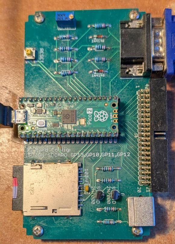 This is easily remedied  Gerbers Gerber_PCB1_2025-01-11.zip BOM and Pick-and-place BOM_Board1_PCB1_2025-01-11.zip Schematic RTCAudio.pdf Cost from JLC USD57 for 5 fully built. Can be hand soldered as no parts smaller than 0805 Edited 2025-01-12 02:26 by matherp |
||||
| Mixtel90 Guru Joined: 05/10/2019 Location: United KingdomPosts: 8964 |
Very nice indeed! :) Mick Zilog Inside! nascom.info for Nascom & Gemini Preliminary MMBasic docs & my PCB designs |
||||
| matherp Guru Joined: 11/12/2012 Location: United KingdomPosts: 11636 |
Oops. Got the pins wrong for the audio. Corrected below Gerber_PCB1_2025-01-11.zip RTCAudio.pdf BOM_Board1_PCB1_2025-01-11.zip |
||||
| Volhout Guru Joined: 05/03/2018 Location: NetherlandsPosts: 5994 |
Hi Peter, It may be me, not understanding the details. But in case you connect audio to GP6/GP7 and I2C to GP14/GP15, VGA reference design 1 configuration is identical to VGA reference design 2. Makes it a lot easier to configure. OPTION RESET VGA DESIGN 2. In stead of manual configuration. Volhout PicomiteVGA PETSCII ROBOTS |
||||
| matherp Guru Joined: 11/12/2012 Location: United KingdomPosts: 11636 |
Good idea. The previous design is still valid though for use on things like the Waveshare 2.8 and 3.5" displays. RTCAudio.pdf Gerber_PCB1_2025-01-12.zip BOM_Board1_PCB1_2025-01-12.zip Edited 2025-01-12 21:59 by matherp |
||||
| matherp Guru Joined: 11/12/2012 Location: United KingdomPosts: 11636 |
The boards have arrived and work perfectly. These were hand soldered and for the first time I used a low temperature solder paste and the heat gun. As you can see it worked perfectly and is pretty much indistinguishable from "factory". The PCBs cost £4.02 for 5 including tax and postage to the UK The 20-way sockets I've installed have long legs so the boards can be stacked  There are two variants of the design as posted above. The last version uses the configuration OPTION AUDIO GP6,GP7 OPTION SYSTEM I2C GP14, GP15 and is compatible with Geoff's VGA board pictured above and on that board can be completely configured with OPTION RESET VGA DESIGN 2 The previous version is designed to be compatible with various of the Waveshare SPI displays like the Pico-RESTOUCH-LCD-2.8/3.5 and is configured with OPTION AUDIO GP4,GP5 OPTION SYSTEM I2C GP6,GP7 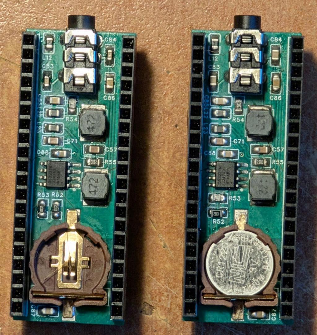 Edited 2025-01-22 02:28 by matherp |
||||
| PhenixRising Guru Joined: 07/11/2023 Location: United KingdomPosts: 2003 |
Can you let us have the product details, please, Pete. Just wanna get it right first time  |
||||
| matherp Guru Joined: 11/12/2012 Location: United KingdomPosts: 11636 |
Solder station Solder paste With the solder paste the thing to look out for is must be Sn42/Bi58 |
||||
| PhenixRising Guru Joined: 07/11/2023 Location: United KingdomPosts: 2003 |
Cheers, I need to start playing with this stuff. The way I understand it is that a stencil can be ordered with the PCB to keep the components squared-up(?) |
||||
| matherp Guru Joined: 11/12/2012 Location: United KingdomPosts: 11636 |
The stencil is just used to apply the solder paste. Then the components still have to be added by hand. Alignment isn't critical as they will self-align when the solder melts. In a perfect world you can use a heated table or oven rather than a heat gun e.g. Heated table Edited 2025-01-22 18:41 by matherp |
||||
| Mixtel90 Guru Joined: 05/10/2019 Location: United KingdomPosts: 8964 |
You could, of course, always get confused (like I did) and end up with 183°C tin/lead rather than 138°C lead-free. :) No, I didn't throw it away, I'm using it anyway. I don't solder SMD LEDs if I can possibly help it. I've never attempted to use a stencil for the paste. The main thing that I've found is don't put too much paste on or you can get Mr Blobby problems, especially around HDMI sockets. :( Mick Zilog Inside! nascom.info for Nascom & Gemini Preliminary MMBasic docs & my PCB designs |
||||
| Volhout Guru Joined: 05/03/2018 Location: NetherlandsPosts: 5994 |
Paste mask is essential for larger IC's, and fine geometies. For individual components as 1206, 0805 or even 0603, the syringe is fine. Also for pin-in-paste application (through hole components). Do not use the bismuth solder paste for power components. Components may desolder themselves and drift off to sandy beaches. (sunny beaches pop up again... wonder why). Volhout Edited 2025-01-22 19:47 by Volhout PicomiteVGA PETSCII ROBOTS |
||||
| The Back Shed's forum code is written, and hosted, in Australia. | © JAQ Software 2026 |
