
|
|
Forum Index : Microcontroller and PC projects : LCD Panel Help Needed
| Page 1 of 4 |
|||||
| Author | Message | ||||
| panky Guru Joined: 02/10/2012 Location: AustraliaPosts: 1111 |
Hi all, I have a need for a large display so after some research, I purchased a 9" TFT LCD panel from BuyDisplay.com. It is based on an SSD1963 controller and has an XPT2046 touch controller. Using OPTION LCDPANEL_7A, it all works after working out the wiring differences on the plug between a real 7" and the 9". Display is clear, no tearing and is centred and touch works fine. The only problem is the colours - green comes out as blue, red comes out as a greenish yellow, grey comes out almost white, white comes out as pale cyan and so on. The display is completely stable and looks great except for the colours. I tried LCDPANEL_7 and again, while the display was fully stable, the colours were off but in a different way. Any suggestions greatly appreciated. panky. Error in above. I did use the correct setups - OPTION LCDPANEL SSD1963_7A,L,48,6 (Explore 100 board) ... and also tried OPTION LCDPANEL SSD1963_7,L,48,6 panky ... almost all of the Maximites, the MicromMites, the MM Extremes, the ArmMites, the PicoMite and loving it! |
||||
Grogster Admin Group Joined: 31/12/2012 Location: New ZealandPosts: 9483 |
I'll be watching this thread with interest, to see what Geoff or Peter say, but it was my understanding that the MM+/MMx/ARMmite/PiCromite don't support LCD's bigger then 8" maximum. You might simply have an LCD geometry which the MM does not support, and so that is what is corrupting the colours. I might well be wrong, but I seem to recall reading that 8" is the current maximum. I also did not think that the 1963 controller chip could support bigger then 8" either, so how they have got a 9" one working on it, could be anyone's guess. Do you happen to have a schematic for your 9" LCD? BuyDisplay are pretty good there, especially if you purchase from them, so ask them to zap you the schematic if you don't already have it. That might reveal something. If you CAN make the 9" display work, that would be ideal for my next project, so yes - watching this one with interest!  Smoke makes things work. When the smoke gets out, it stops! |
||||
| panky Guru Joined: 02/10/2012 Location: AustraliaPosts: 1111 |
G, Yes, I do understand the current limit of 8", however checking the specs of the 7", 8" and 9" panels, they all are 800 x 480, all use the SSD1963 and XPT2046. Looking at the example code for use with Arduino, they all appear to have very similar setups with some minor variations on timing which I assume is just related to physical size. The only major difference is the pinout but I have that worked out and flying leads across to an Explore 100. So I took the chance to have a play around and try to get it to work The fact that the display is completely stable with complex text and GUI elements displayed would indicate that in genereral, it is 99% compatible - the only issue is colour and in fact it is red that is missing although I do get some white (ish) elements displayed. I have tried varying combos of colour using the CLS command but most turn out to blue through green. Could be timing related to passing colour info? Screenshot is as shown below 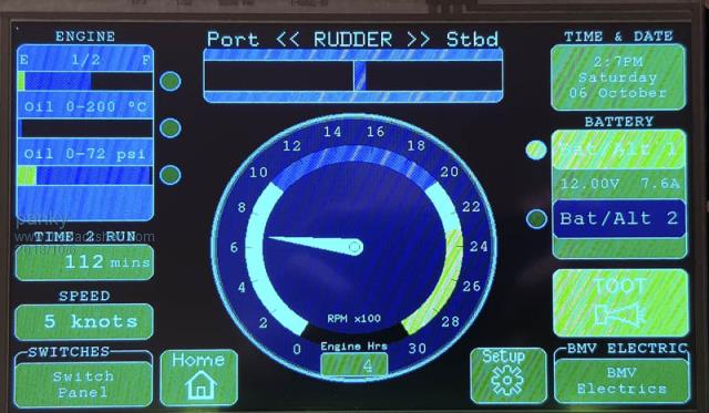 Ignore the striations - they are an artifact introduced by the camera. All colours, while wrong in colour are solid blocks and bright and clear. The needle in the circular gauge should be gray but comes up as off white with a blue tinge. The blue in the centre of the gauge should be darkish gray as should the background on the engine frame and so on and so forth. panky. ... almost all of the Maximites, the MicromMites, the MM Extremes, the ArmMites, the PicoMite and loving it! |
||||
TassyJim Guru Joined: 07/08/2011 Location: AustraliaPosts: 6219 |
It is possible that your display is in the wrong mode. You can have 8080 or 6800 mode. I don't know what mode the 'normal' displays use. Assuming I have looked at the correct board, there is a pair of resistors R3 and R4 on the display board that are used to set the mode. 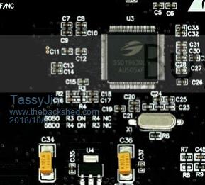 I would check with Peter or Geoff before attacking the board. The pixel data mapping appears to be the same for both modes so I could be wrong. If it can be got working, it will be a popular choice. VK7JH MMedit |
||||
| shallowal Regular Member Joined: 26/07/2018 Location: AustraliaPosts: 58 |
Looks to me like red is not displaying at all. Faulty panel?  Allan Allan |
||||
| TassyJim Guru Joined: 07/08/2011 Location: AustraliaPosts: 6219 |
Something to try is: OPTION LCDPANEL SSD1963_8,L,48,6 The 8inch is not documented but might be in the firmware. Jim VK7JH MMedit |
||||
| panky Guru Joined: 02/10/2012 Location: AustraliaPosts: 1111 |
Bingo Jim  you're a wizard! you're a wizard!I thought I had tried that earlier but obviously not. I can report that the 9" TFT LCD from BuyDisplay.com part number ER-TFTM090 v10 9"-800xRGBx480 Dots TFT LCD Module with SSD1963 and Touch Controller XPT2046 works straight out of the box using OPTION LCDPANEL SSD1963_8,l,48,6 (the last two numbers are for my Explore 100 that I am driving it with). Diagram of the pinout as below 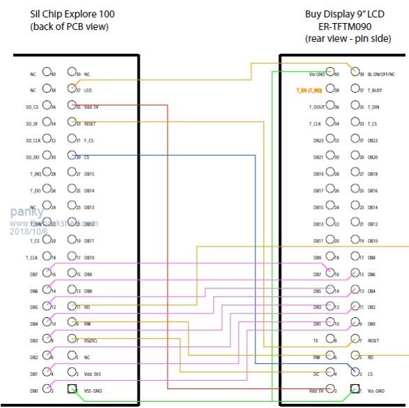 panky ... almost all of the Maximites, the MicromMites, the MM Extremes, the ArmMites, the PicoMite and loving it! |
||||
| TassyJim Guru Joined: 07/08/2011 Location: AustraliaPosts: 6219 |
Good news. One happy Guinea pig. Which interface did you get 6800 or 8080? 3.3V or 5V? They seem to have a few options to choose from when ordering. Jim VK7JH MMedit |
||||
| panky Guru Joined: 02/10/2012 Location: AustraliaPosts: 1111 |
8080 and 5V. Am running the whole thing off 5V that is feeding the Explore 100. Full brightness on the LCD plus the Explore 100 pulls 580mA. The unit can operate as 8080 or 6800 and 5V or 3V3 with both cases settable by jumpers. Default shipping is 8080 and 5V. The unit I ordered initially was the 10" but the controller was different so I emailed BuyDisplay.com and said what I needed was a 9" with SSD1963 and XPT2046 resistive - I didn't ask for the pin header or any font chips but as I had over ordered (and paid for the 10") they threw in the pin header and the touch chip. The BuyDisplay.com folks were extremely helpful and responsive and although it cost extra, they shipped Fedex and it took just 10 days from start to finnish. Good experience all around. I am now working on an adaptor board that will connect to the 7" header and re-map to a header for the 9". Have not had a chance to test on MMX or ARMMite platforms yet but hope to get to that over the next few weeks. Cheers, panky. ... almost all of the Maximites, the MicromMites, the MM Extremes, the ArmMites, the PicoMite and loving it! |
||||
| panky Guru Joined: 02/10/2012 Location: AustraliaPosts: 1111 |
Forgot to add, SD card on the LCD is a 4 bit paralled and I understand this is not supported so if you need an SD card and want to use this unit, you will need one on the main PCB like Grogsters 1D Explore 100 board. panky. ... almost all of the Maximites, the MicromMites, the MM Extremes, the ArmMites, the PicoMite and loving it! |
||||
| matherp Guru Joined: 11/12/2012 Location: United KingdomPosts: 10066 |
You should still be able to use it in SPI mode D0 = MISO CMD = MOSI CLK = CLK D3 = CS D2 = N/C D1 = N/C CD = CD if wired |
||||
| Grogster Admin Group Joined: 31/12/2012 Location: New ZealandPosts: 9483 |
VERY interesting. Please post some new photos if you get time. I might just have to check these ones out. I assume these are the ones you got: 9" LCD LINK EDIT: @ panky: From 9" PDF manual for this display, page 10, section 4.3: 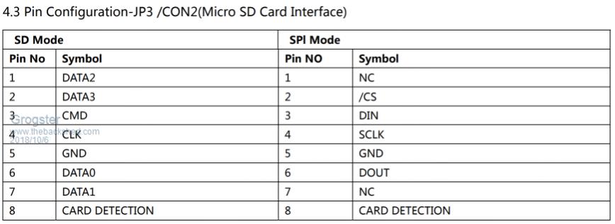 Smoke makes things work. When the smoke gets out, it stops! |
||||
| Geoffg Guru Joined: 06/06/2011 Location: AustraliaPosts: 3269 |
You were lucky that the setup for the 8" display worked. While it looks like all the various LCD panels are similar (ie, 1965 controller, 800x480 pixels, etc) there can be large variations between different manufacturers - even for panels of the same size. MMBasic loads into the graphics controller chip over a dozen different parameters to suit each LCD assembly (called the "glass" in the industry). This includes things like clock speed, pulse widths, clock sequence, etc. Fortunately the Chinese seems to have standardised the parameters for the 4.3", 5" and 7" sized glass so you would be unlucky to get one of these that did not work with the Micromite. But the same is not true for displays based on 8" and larger glass, so you can count yourself lucky. I did consider making all these parameters configurable but it was not feasible. They all interact with each other and given that the Chinese rarely publish detailed specs it is more of a tedious guessing game to get the right setup for any particular display. Not something for the faint hearted. Geoff Geoff Graham - http://geoffg.net |
||||
| Grogster Admin Group Joined: 31/12/2012 Location: New ZealandPosts: 9483 |
Well then, based on that, I think panky has earned a beer.  He's taken the plunge, and found it works, which proves that those 9" ones from EastRising(buydisplay.com) should therefore work on any MM+ if they work OK for him on one. The code to control them is probably exactly the same across all models, so if they work on the MM+, they should work on all the other advanced MM chips. False logic?  Smoke makes things work. When the smoke gets out, it stops! |
||||
| WhiteWizzard Guru Joined: 05/04/2013 Location: United KingdomPosts: 2927 |
@Grogster Any chance of an adapter PCB? It is on my long to-do list. I hard wired several 8" TFTs and it is a right PITA! A PCB would be a massive benefit for many people here. Two 40pin headers; one either end of the PCB, then TFT is effectively 180deg rotated (no problem with L/RL and P/RP parameters in the OPTION LCDPANEL setting). Will only add a slight thickness to the 'sandwich'. Email me if you need more info! WW |
||||
| Geoffg Guru Joined: 06/06/2011 Location: AustraliaPosts: 3269 |
Yes, I could use a couple of them also. Geoff Graham - http://geoffg.net |
||||
| Grogster Admin Group Joined: 31/12/2012 Location: New ZealandPosts: 9483 |
I would, but panky said he was going to do one - perhaps he will share his design? Otherwise, I can whip one up no problems. I might do one anyway, cos if I get one of those 9" LCD's to play with, I will need an adaptor like that, so I either get one of panky's ones, or I produce my own one..... EDIT: @ Geoff or Peter - Could you guys ever make use of the font chip that is an optional extra on the BuyDisplay boards? If you could, or thought you might one day, I could design an adaptor PCB that covers JP1, JP2 and JP3 and remaps all those to the E100 40-pin GPIO port. JP1 gives access to a W25Q128JV flash chip - which I think matherp has already written drivers for, and also one of four types of font chip, those being ER3300, ER3301, ER3303 and ER3304. I am having a wee look at the datasheets for these now. While the font chip may not be something that can be used, perhaps it would still be useful to have access to the optional flash memory IC, yes? EDIT: ER3304 is probably the font chip to go for if any. It contains 14 ASCII fonts. The font chip idea might be a moot point, as the MM has the ability to load whatever font you want via DefineFont. Have I just answered my own question? (rhetorical) Smoke makes things work. When the smoke gets out, it stops! |
||||
| panky Guru Joined: 02/10/2012 Location: AustraliaPosts: 1111 |
Don't go rushing out to order one yet! While it ran all yesterday afternoon without a hitch, coming into the shed this morning and the display is corrupted. Not sure why yet but I did move the "rat's nest" of interconnect wires. Display does not seem to initialise properly at the moment. Am going to wire wrap up an interface board as an interim to continue the testing. Will keep all advised. ... almost all of the Maximites, the MicromMites, the MM Extremes, the ArmMites, the PicoMite and loving it! |
||||
| TassyJim Guru Joined: 07/08/2011 Location: AustraliaPosts: 6219 |
Too late. I ordered mine a couple of hours ago to beat the rush. Jim VK7JH MMedit |
||||
| Grogster Admin Group Joined: 31/12/2012 Location: New ZealandPosts: 9483 |
I THINK you are still safe to order them, but I await panky's follow-up with anticipation. I suspect that the LCD and MM are fine, and it's just you disturbed one of the critical data lines or something to the display. All control lines and the data bus have to be intact for the display to work correctly, as you probably know. Disturbing bit-4 or something like the DC/RS line will cause all kinds of merry hell with the display. Hope you get it sorted. EDIT: Damn, Jim, that puppy is so cute!  Smoke makes things work. When the smoke gets out, it stops! |
||||
| Page 1 of 4 |
|||||
| The Back Shed's forum code is written, and hosted, in Australia. | © JAQ Software 2025 |
