
|
|
Forum Index : Microcontroller and PC projects : Armmite L4 battery miser, first beta
| Page 1 of 8 |
|||||
| Author | Message | ||||
| matherp Guru Joined: 11/12/2012 Location: United KingdomPosts: 11589 |
Please find attached a first beta of MMBasic running on the STM32L432. Recommended platform is the NUCLEO-L432KC. 2018-11-08_184619_ArmmiteL4.zip Use the STM32 ST-LINK Utility to flash the chip Valid CPU speeds and power figures are: [code]CPU Power 80 11.2mA 48 6.43mA default 32 4.44mA 24 3.45mA 16 2.49mA 8 1.4mA 4 0.9mA 2 0.65mA PAUSE 0.57mA - unless PWM is active SLEEP 1.8uA [/code] NB: even when sleeping the RTC is running and the time and date will survive resetting the processor but obviously not power down or reflashing. There are a number of things to understand about these figures: 1: you must cycle the power after flashing the chip otherwise sleep values will be much higher 2: Switching to CPU 80 and then back to one of the slower modes will increase power utilisation slightly as the PLL cannot be disabled without resetting the chip 3: Clocks for COM1, ADC, I2C, DAC, random number generator and PWM are turned off on reset. Using each of these functions will incrementally increase power very slightly during running and sleep. 4. These figures are measured at JP1 on the Nucleo. To use the Nucleo without the ST-LINK being powered remove SB4 and power the Nucleo with 3.3V at the 3V3 pin. 5. The TEMPR commands and functions will transparently increase the clock speed during communication if the CPU speed is below 24MHz 6. The WS2812 command will transparently increase the clock speed during communication if CPU speed is below 80MHz Pinout is as per the attached table. The parameter in quotes is the Nucleo silkscreen identifier { NULL, 0, PUNUSED , NULL, 0,""}, // pin 1 VDD { NULL, 0, PUNUSED , NULL, 0,""}, // pin 2 OSC32_IN { NULL, 0, PUNUSED , NULL, 0,""}, // pin 3 OSC32_OUT { NULL, 0, PUNUSED , NULL, 0,""}, // pin 4 NRST { NULL, 0, PUNUSED , NULL, 0,""}, // pin 5 VDD { GPIOA, GPIO_PIN_0, DIGITAL_IN | DIGITAL_OUT | ANALOG_IN , ADC1, ADC_CHANNEL_5,"A0"}, // pin 6 COUNT/WAKEUP/IR { GPIOA, GPIO_PIN_1, DIGITAL_IN | DIGITAL_OUT | ANALOG_IN , ADC1, ADC_CHANNEL_6,"A1"}, // pin 7 SPI-CLK { NULL, 0, PUNUSED , NULL, 0,""}, // pin 8 Console-TX { GPIOA, GPIO_PIN_3, DIGITAL_IN | DIGITAL_OUT | ANALOG_IN , ADC1, ADC_CHANNEL_8,"A2"}, // pin 9 PWM2A { GPIOA, GPIO_PIN_4, DIGITAL_IN | DIGITAL_OUT | ANALOG_IN , ADC1, ADC_CHANNEL_9,"A3"}, // pin 10 DAC1 { GPIOA, GPIO_PIN_5, DIGITAL_IN | DIGITAL_OUT | ANALOG_IN , ADC1, ADC_CHANNEL_10,"A4"}, // pin 11 DAC2 { GPIOA, GPIO_PIN_6, DIGITAL_IN | DIGITAL_OUT | ANALOG_IN , ADC1, ADC_CHANNEL_11,"A5"}, // pin 12 SPI-IN { GPIOA, GPIO_PIN_7, DIGITAL_IN | DIGITAL_OUT | ANALOG_IN , ADC1, ADC_CHANNEL_12,"A6"}, // pin 13 SPI-OUT { GPIOB, GPIO_PIN_0, DIGITAL_IN | DIGITAL_OUT | ANALOG_IN , ADC1, ADC_CHANNEL_15,"D3"}, // pin 14 { GPIOB, GPIO_PIN_1, DIGITAL_IN | DIGITAL_OUT | ANALOG_IN , ADC1, ADC_CHANNEL_16,"D6"}, // pin 15 { NULL, 0, PUNUSED , NULL, 0,""}, // pin 16 VSS { NULL, 0, PUNUSED , NULL, 0,""}, // pin 17 VDD { GPIOA, GPIO_PIN_8, DIGITAL_IN | DIGITAL_OUT , NULL, 0,"D9"}, // pin 18 PWM1A { GPIOA, GPIO_PIN_9, DIGITAL_IN | DIGITAL_OUT , NULL, 0,"D1"}, // pin 19 COM1-TX/(PWM1C to be implemented) { GPIOA, GPIO_PIN_10, DIGITAL_IN | DIGITAL_OUT , NULL, 0,"D0"}, // pin 20 COM1-RX/(PWM1D to be implemented) { GPIOA, GPIO_PIN_11, DIGITAL_IN | DIGITAL_OUT , NULL, 0,"D10"}, // pin 21 PWM1B { GPIOA, GPIO_PIN_12, DIGITAL_IN | DIGITAL_OUT , NULL, 0,"D2"}, // pin 22 USART1-DE/COUNT { GPIOA, GPIO_PIN_13, DIGITAL_IN | DIGITAL_OUT , NULL, 0,""}, // pin 23 SWDIO - not broken out on Nucleo { GPIOA, GPIO_PIN_14, DIGITAL_IN | DIGITAL_OUT , NULL, 0,""}, // pin 24 SWCLK - not broken out on Nucleo { NULL, 0, PUNUSED , NULL, 0,""}, // pin 25 Console-RX { GPIOB, GPIO_PIN_3, DIGITAL_IN | DIGITAL_OUT , NULL, 0,"D13"}, // pin 26 Green-LED/SPI2-CLK { GPIOB, GPIO_PIN_4, DIGITAL_IN | DIGITAL_OUT , NULL, 0,"D12"}, // pin 27 SPI2-IN { GPIOB, GPIO_PIN_5, DIGITAL_IN | DIGITAL_OUT , NULL, 0,"D11"}, // pin 28 SPI2-OUT { GPIOB, GPIO_PIN_6, DIGITAL_IN | DIGITAL_OUT , NULL, 0,"D5"}, // pin 29 I2C-SCL { GPIOB, GPIO_PIN_7, DIGITAL_IN | DIGITAL_OUT , NULL, 0,"D4"}, // pin 30 I2C-SDA { NULL, 0, PUNUSED , NULL, 0,""}, // pin 31 BOOT0 { NULL, 0, PUNUSED , NULL, 0,""}, // pin 32 VSS In all MMBasic commands the Nucleo identifier can be substituted for the pin number e.g. SETPIN D13,DOUT PIN(D13)=1 'light LD3 ? TEMPR(A5) PORT(A0,3,D2,3)=&H3F Very slow clock speeds may compromise activities like editing The command set is the same as the MM2 with the following exceptions: Missing: all drawing, font and TFT capability obsolete commands and functions as per MM2 manual RANDOMIZE command, STM32 has hardware random number generator so not needed LIBRARY command Added: DISTANCE command as per earlier versions of MM2 DHT22 command as per earlier versions of MM2 LONGSTRING commands and functions as per MMX/ARMMITE H7 WS2812 command as per MMX/ARMMITE H7 DAC command as per ARMMITE H7 DAY$ function as per ARMMITE H7 SPI2 commands and functions as per MM+/MMX/ARMMITE H7 Different: TIME$ command sets the value from the RTC TIME$ function returns the value in the RTC DATE$ command sets the value from the RTC DATE$ function returns the value in the RTC MM.DEVICE$ returns "ARMMITE L4" Other: Things I've forgotten |
||||
| circuit Guru Joined: 10/01/2016 Location: United KingdomPosts: 305 |
Bucketloads of appreciation, sir! My board is due in from RS this morning and I am most excited about exploring the potential of this new chip. Peter, your efforts are most valued. |
||||
TassyJim Guru Joined: 07/08/2011 Location: AustraliaPosts: 6541 |
My parcel arrived from Element14 today so something to do tomorrow Thanks Peter VK7JH MMedit |
||||
| lizby Guru Joined: 17/05/2016 Location: United StatesPosts: 3790 |
Great work and thanks. My L4s should arrive next week from Digikey. Are benchmark times at 80mHz still showing about the same as the MX170? If so, any handle on why that may be (e.g., L4 instructions take more cycles, more instructions required for same amount of MMBasic work)? Does your list of instructions included and excluded imply that all SD card interactions are available (that alone would make this a valuable step-up from the MX170 in certain circumstances, even at the same speed)? If so, what does MEMORY show initially? (I personally would be glad to give up some MMBasic memory to gain full SD card use.) Love the wake-up from IR option. PicoMite, Armmite F4, SensorKits, MMBasic Hardware, Games, etc. on FOTS |
||||
| Volhout Guru Joined: 05/03/2018 Location: NetherlandsPosts: 5961 |
amazing !!! less than 2 weeks ago, there was a post called "thinking about...." and today the platform is chosen, and the code is in beta..... matherp, you are a giant !!! Volhout PicomiteVGA PETSCII ROBOTS |
||||
| JohnS Guru Joined: 18/11/2011 Location: United KingdomPosts: 4337 |
Bottom of this thread - looks like no SD. SD card John |
||||
| matherp Guru Joined: 11/12/2012 Location: United KingdomPosts: 11589 |
Longer term my thoughts are to include SPI flash support with SPIFFS |
||||
| matherp Guru Joined: 11/12/2012 Location: United KingdomPosts: 11589 |
I've now included support for drawing functions and user mode display drivers 2018-11-09_022053_ArmmiteL4.zip 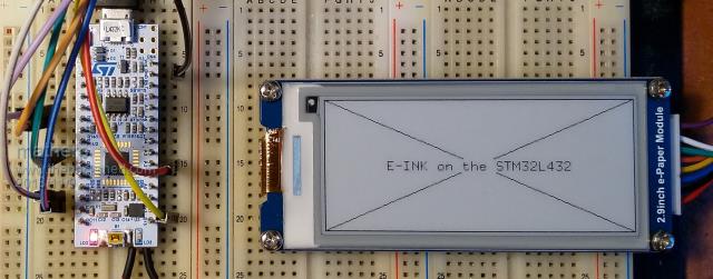 The example program uses the STM to switch power to the display so, as seen in the picture, the display is actually powered off - zero current usage - and the STM32 is sleeping @1.8uA. Based on using a normal 18650 LiFePo cell this should run like this for just over 100 years  2018-11-09_022827_epaper2.9.zip |
||||
| circuit Guru Joined: 10/01/2016 Location: United KingdomPosts: 305 |
Well, I am up and running. Code downloaded okay with ST-Link. I am using MMEdit to communicate and I was able to run direct commands okay. MEMORY declared itself fine, MM.VER also but there seemed to be no response to CTL-C. Then I uploaded a simple DO-LOOP to flash the green LED and it ran fine. Then I set OPTION AUTORUN ON and now I cannot get it to BREAK. I have tried sending breaks in MMEdit and in Teraterm but the green LED just keeps flashing away. I guess that I will just try and reload the code later. |
||||
| matherp Guru Joined: 11/12/2012 Location: United KingdomPosts: 11589 |
Why is the first thing users do with new firmware is tell it to autorun  and why is it that in development it is the one thing you never test as it is completely irrelevant to developing and testing the main functionality  Try this: 2018-11-09_051818_ArmmiteL4.zip |
||||
OA47 Guru Joined: 11/04/2012 Location: AustraliaPosts: 1050 |
Thanks heaps Peter, it looks like this weekend may not be as dull as first thought. OA47 |
||||
| TassyJim Guru Joined: 07/08/2011 Location: AustraliaPosts: 6541 |
ctrl-C works as expected with a running program but if you do crtl-C while at the command prompt, it sits in the input buffer until another character is sent. try ctrl-C NEW and you get I thought MMEdit was broken for a minute. VK7JH MMedit |
||||
| TassyJim Guru Joined: 07/08/2011 Location: AustraliaPosts: 6541 |
I have been experimenting with running the device standalone. I am running it from external 5V I found that as soon as I unplugged the USB cable, the reset pin was pulled low by the powered-down ST-link. I tried a 10k resistor to 3.3V but reset was still pulled too low to run. The manual does tell you to remove SB9 when running of external 3.3V and it is a bit vague about what to do when using external 5V. The link has to be removed! I then tried to re-flash the chip without SB9 in place. By holding the reset button in while clicking on 'connect', I was able to get a connection and proceeded to erase and re-flash without any further need to press reset. I can now plug and unplug the USB without upsetting the running program. Happy chappy! Jim VK7JH MMedit |
||||
| matherp Guru Joined: 11/12/2012 Location: United KingdomPosts: 11589 |
Hopefully fixed now 2018-11-09_212923_ArmmiteL4.zip |
||||
| viscomjim Guru Joined: 08/01/2014 Location: United StatesPosts: 925 |
Hi Peter. This is great and I want to build a battery powered device using this. I noticed you had an e ink display hooked up and I think this would be the perfect combination for a low power device. I want to add a smaller version (1.54") of the e ink display - HERE is the link for the one I want to use. Can you tell me if this smaller display would be useable with the armmite L4? Thanks for this port, very impressive. Can't wait for my boards to arrive from digikey. |
||||
| matherp Guru Joined: 11/12/2012 Location: United KingdomPosts: 11589 |
Yes, it would certainly work with a user driver like my example above but would need the initialisation sequence sorting out. I haven't got this size. Remember though they are V..E..R..Y S..L..O..W and you get artifacts as they update if that matters |
||||
| viscomjim Guru Joined: 08/01/2014 Location: United StatesPosts: 925 |
Thanks Peter, maybe I'll just stick with the small I2C oled and only power it when the user needs to access any info, via a button press or something like that. |
||||
| matherp Guru Joined: 11/12/2012 Location: United KingdomPosts: 11589 |
This version includes some new display drivers 2018-11-10_053808_ArmmiteL4.zip 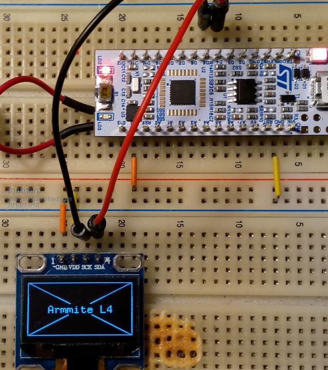 Drivers supported are: Nokia 5110 over SPI2 OPTION LCDPANEL N5110, orientation, DCpin, RSTpin, CEpin and SSD1306 over I2C as in the picture OPTION LCDPANEL SSD1306I2C, orientation [,Xoffset] The optional parameter Xoffset is used to correct the display on 1.3" versions and should be set to 2 in this case. You may also find that ILI9341, ST7735 and ILI9163 work as per the MM/MM+ over SPI2  but be warned these may be removed depending on space considerations as I implement more low power devices. but be warned these may be removed depending on space considerations as I implement more low power devices. |
||||
| OA47 Guru Joined: 11/04/2012 Location: AustraliaPosts: 1050 |
I have had a bit of a scratch around and cant find a reference to how much current the STM32L4 pins can sink/source. Only ref close is "datasheet of the stm32f4xx specifies a sink/source current of 25 mA per pin" Can someone help me out here? OA47 |
||||
| matherp Guru Joined: 11/12/2012 Location: United KingdomPosts: 11589 |
DS11451 page 66 - 20mA |
||||
| Page 1 of 8 |
|||||
| The Back Shed's forum code is written, and hosted, in Australia. | © JAQ Software 2026 |
