
|
|
Forum Index : Microcontroller and PC projects : Just for fun - bad harmonics....
| Author | Message | ||||
Grogster Admin Group Joined: 31/12/2012 Location: New ZealandPosts: 9975 |
Hi all.  Testing an FM transmitter today. Output is set for 1W into dummy load, with spectrum analyser looking at it. Check this out: 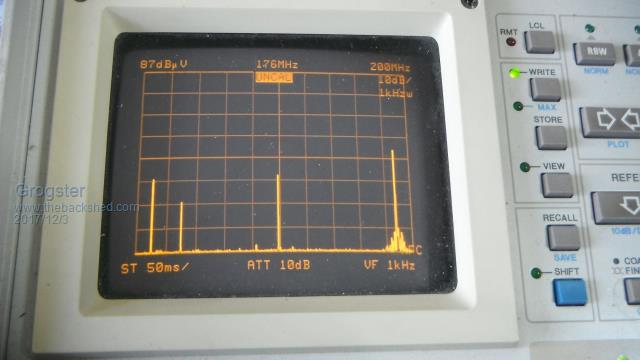 Centre frequency is 176MHz, and is looking at the 2nd harmonic of the carrier frequency which is 88MHz. No modulation, just "Dead-air" carrier. 2nd Harmonic is about 2dB UP on the carrier, and check out that 3rd harmonic at 264MHz! It is about 12dB UP on the carrier - bloody hell - with some kind of spurious signals hanging around either side of it. Nasty.....   This is non-compliant in it's current state. The on-board filter is supposed to be broadband, but it obviously is not. If I reset the output frequency to 108MHz with same 1W output power, the harmonics are much more in line with what I would like to be seeing on the spectrum analyser, although still peaking higher then I would like to see:(2nd is 10dB down, 3rd is 20dB down - more in line with how it should be) 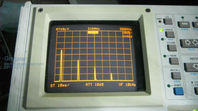 So the on-board filter is obviously designed to favour the upper-end of the FM band, so adding an additional LFP should clean it up enough to use, but not one to put on-air on the low-end of the FM band, that's for sure!!!  Smoke makes things work. When the smoke gets out, it stops! |
||||
TassyJim Guru Joined: 07/08/2011 Location: AustraliaPosts: 6538 |
That's not harmonics, this is harmonics: Electric fence unit 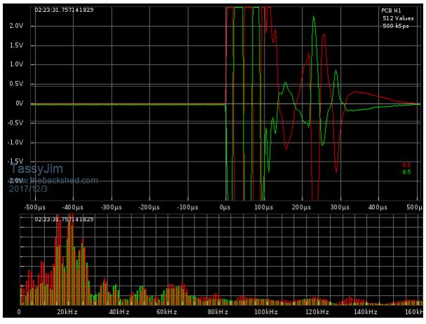 A 'good' fence looks like this 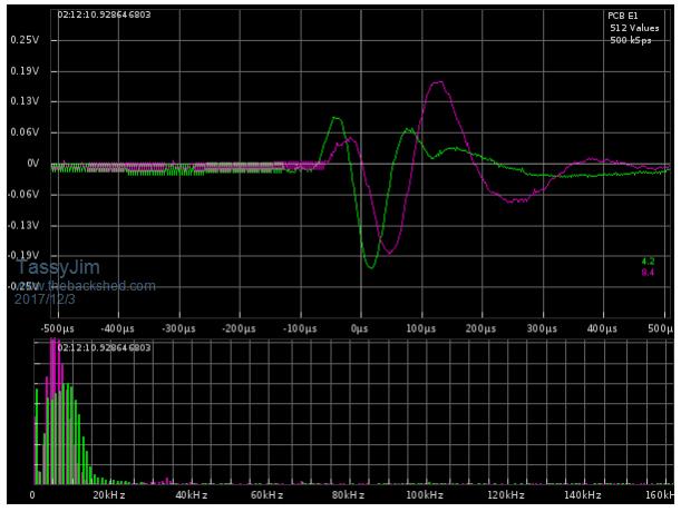 Jim VK7JH MMedit |
||||
| Grogster Admin Group Joined: 31/12/2012 Location: New ZealandPosts: 9975 |
Crikey! Other members feel free to post your nasty scope/analyser shots.  EDIT: Jim - is that a "That's not a knife. That's a knife!" reference by any chance?!  Smoke makes things work. When the smoke gets out, it stops! |
||||
crez Senior Member Joined: 24/10/2012 Location: AustraliaPosts: 153 |
It is behaving as if it requires tuning after a frequency change. Are the any on board trimmer caps or adjustable ferrite coil slugs? I have been designing and building these low power FM broadcast units for years and they don't leave our workshop with harmonics worse than -65dB David |
||||
| Grogster Admin Group Joined: 31/12/2012 Location: New ZealandPosts: 9975 |
One slug, which is the main RF input to the PA from the exciter side of the circuit. I tried twiddling that a little, but it did nothing to the harmonics at all, but it did allow you to peak the output power. The rest of the on-board filter is SMD caps and close-wound inductors. I could start spreading and compressing those inductors as an experiment I guess. Smoke makes things work. When the smoke gets out, it stops! |
||||
| crez Senior Member Joined: 24/10/2012 Location: AustraliaPosts: 153 |
At least you have test equipment so you can see what is going on. Maybe take a picture of the coils before you start so you can go back if you don't get an improvement. What is the output device? |
||||
| Grogster Admin Group Joined: 31/12/2012 Location: New ZealandPosts: 9975 |
The final is marked as "c1971", so I expect that to be a 2SC1971 - a very common RF transistor used in many an FM transmitter kit I have seen capable of over a watt or two. The driver transistor is marked as "C2053", which I also expect that to be a 2SC2053. I was wrong about the placement of the slug thing too. It is in between the driver and the final. Smoke makes things work. When the smoke gets out, it stops! |
||||
| The Back Shed's forum code is written, and hosted, in Australia. | © JAQ Software 2026 |
