
|
|
Forum Index : Solar : Build a Mppt 3 Kw Charge Controller
| Author | Message | ||||
| Warpspeed Guru Joined: 09/08/2007 Location: AustraliaPosts: 4406 |
I agree, 22uH is a pretty good target inductance for this. Saturation tester is a must have, its fast and easy and gives final proof that the numbers have not lied. I still like to work things out first though from published data, especially the potential for excessive core loss and core heating problems. That core has a very soft saturation characteristic. At 80 amps the inductance will be down to around 12uH to 13uH which is where its going to be running with 80 amps of constant dc flowing. Its not ramping up from nothing as it does with the inductance tester. As you can see from the curve, at 42 Orsteads (with 125u material) the initial permeability falls to about 45%. If you had used the 60u material, the initial permiability falls to roughly 77% from an initial 60u. 45% of 125u is more than 77% of 60u. But not by much. The 60u material would require a couple of extra turns to reach the same inductance as the 125u material. 125u material 8 turns for 22uH with 80 amps dc ? 60u material 10 turns for 22uH with 80 amps dc ? I think what you already have there will work very well. 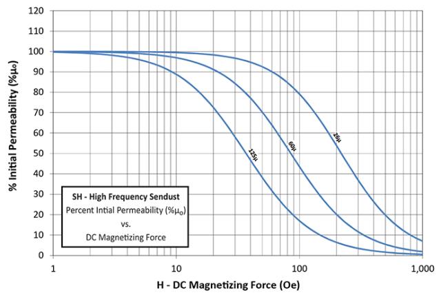 If you can increase the turns count from six to eight, that should get you back up into the 22uH region with full dc current flowing. Cheers, �Tony. |
||||
| Solar Mike Guru Joined: 08/02/2015 Location: New ZealandPosts: 1123 |
Thanks for that Tony, see how I go with number of turns, can always increase the switching frequency somewhat so less L is required, 100Khz was a value I plucked out of the air, so to speak. Cheers Mike |
||||
| Warpspeed Guru Joined: 09/08/2007 Location: AustraliaPosts: 4406 |
With regard to output capacitance, as you say, a very low impedance battery does not need very much at all. My own Lithium battery charger is rather different, 100v, only 8 amps max, and its 20Khz. What I did find was that an output capacitor will resonate with the choke to create a series tuned circuit. (in your case 8,200uF + 22uH = 375Hz). That tuned circuit creates a massive sudden phase shift around resonance and a peak in the loop gain of the control loop. Gain will need to roll off rapidly to below unity at 375 Hz for stability. A battery charger does not need a super fast transient response anyway, but stability in the control loop is somewhat necessary. The less output capacity you can get away with, the easier taming the control loop will be. Cheers, �Tony. |
||||
| Solar Mike Guru Joined: 08/02/2015 Location: New ZealandPosts: 1123 |
Latest update, pcb has been re-designed to allow better current distributions, incorporate automatic switching from sync to async operation of buck converter when charge currents < 2.6amps, allowances have made for higher frequency PWM switching of 150Khz. Circuit is essentially similar to previous. 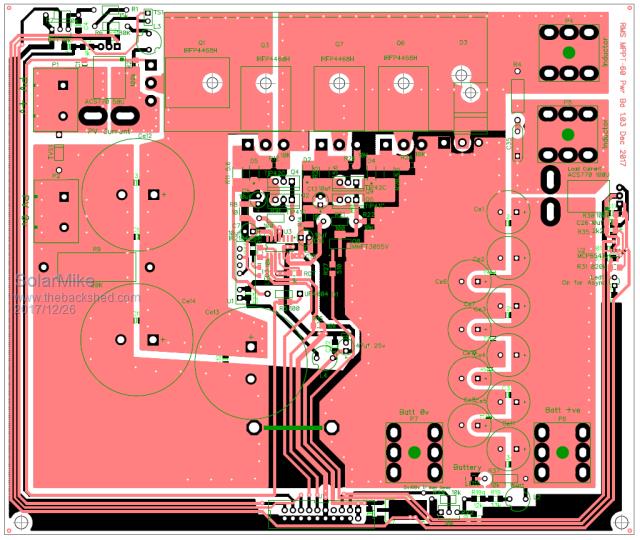 Just waiting on parts to assemble, no control board yet, thats next. Does anyone have any links for online double sided PCB 2oz copper, queried few sellers on EBay and AliExpress, seems all they sell is 1oz or less; have just about used up the remains of a 2m x 1.2m sheet purchased over 30 years ago. Cheers Mike |
||||
Madness Guru Joined: 08/10/2011 Location: AustraliaPosts: 2498 |
https://www.ebay.com.au/itm/10pc-FR4-Blank-PCB-board-200x300mm-t-1-6mm-2-oz-2-side-RoHS-NAN-YA-Taiwan/140925020417?hash= item20cfc92901:g:YJMAAMXQBwlRMaCr There are only 10 types of people in the world: those who understand binary, and those who don't. |
||||
| Solar Mike Guru Joined: 08/02/2015 Location: New ZealandPosts: 1123 |
Thanks Madness, sent the seller an email, they dont ship to NZ by default, see what they say... Used to be a time where you could purchase huge sheets of this stuff from the electrical supply outlets, had to cut it up with a big guillotine, now no one seems to sell it, don't know where the PCB manufactures in Auckland get it from... More changes to the PCB, squeezed it in a bit, now exactly 200x150mm so fits into standard sizes of PCB available for sale. Added extra bridging on top layer where a piece of copper foil can be soldered for better current flow. 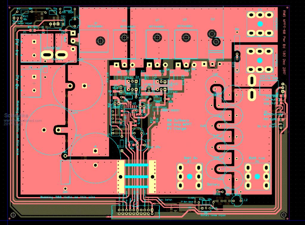 Cheers Mike |
||||
| Madness Guru Joined: 08/10/2011 Location: AustraliaPosts: 2498 |
I have bought at least 5 times from that seller in Taiwan, 10 200 X 300 2oz boards cost me about $110 AUD delivered. Last lot I got each board was in its own sealed plastic bag which is nice. Big sheets would be a difficult to get shipped. Hardly worth etching your own except for prototyping. There are only 10 types of people in the world: those who understand binary, and those who don't. |
||||
| Solar Mike Guru Joined: 08/02/2015 Location: New ZealandPosts: 1123 |
Mine arrived yesterday from the same seller, all nicely packed in individual plastic bags, shipping cost more than the product. Cannot purchase this in NZ any more, no demand I guess or no skills out there to build stuff any more. More of those powdered iron cores arrived at the same time, so now I can test a coil using 5 cores; here are the results from the coil saturation tester. Test coil was 46 turns 1mm dia copper wire wound over 5 stacked cores. Yellow trace shows coil current 5 amps/division, saturation starting to kick in at 15 amps over a time of 570us with 30 volts supply. L = 1140uH or 0.53uH T^2 So 8 Turns = 34uH @86amps, this is perfect for >60 amp charge current output of the 3KW Mppt controller I increased the current to 35 amps and core was still in soft saturation with a decreasing inductance; so I reckon you could use 5 of these with 10 turns for a 5KW OZInverter (48 volts) transformer choke. 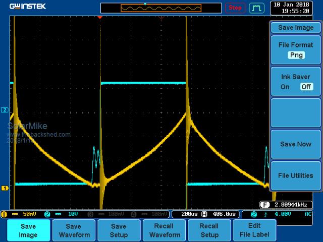 Have been working on cpu driver design, more in next post... Cheers Mike |
||||
| Solar Mike Guru Joined: 08/02/2015 Location: New ZealandPosts: 1123 |
Proposed Controller Schematic: Schematic_Control_Board_1.03.pdf 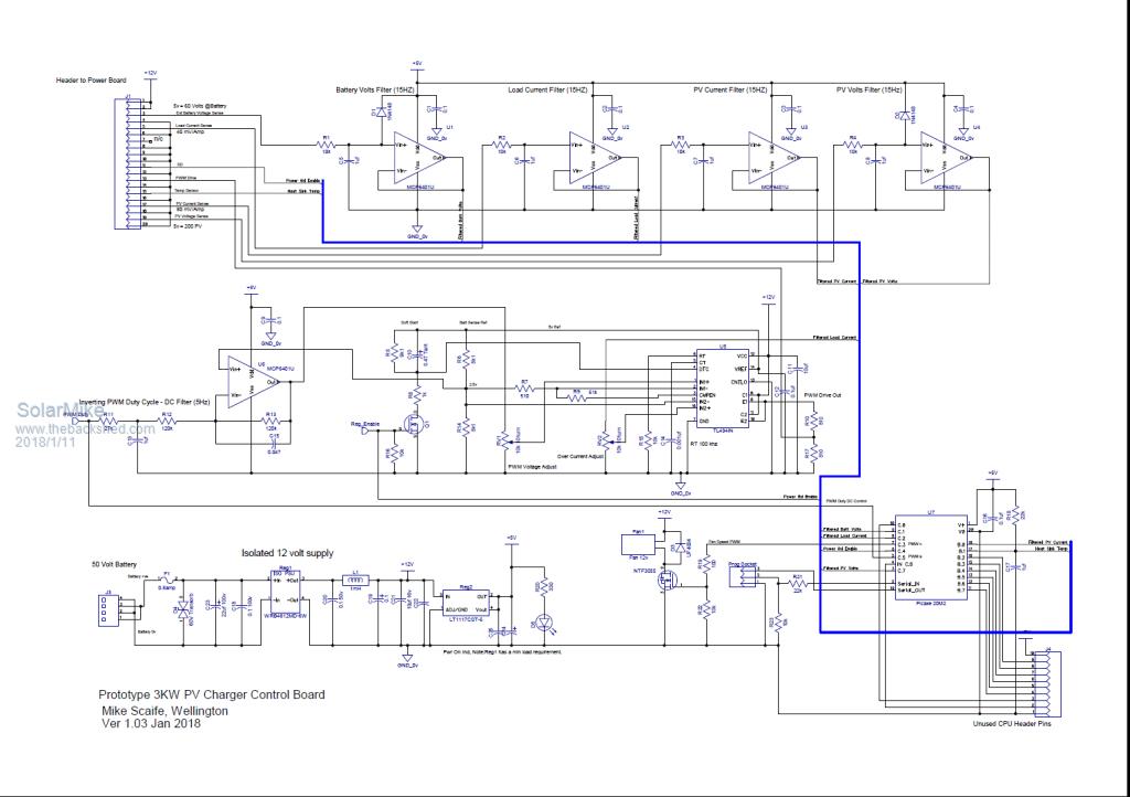 Notes: I want to run the PWM at 100Khz in order to keep the size of the main inductor small as possible, however the common 8 bit controllers dont have enough PWM duty cycle resolution at this speed to enable fine granularity of switching, so have opted here to use a switch mode psu controller TL494 as the main control device. The TL494 has been around for may years and seems very versatile, it has 2 opamp gain stages with a common output that controls the switching dead time comparator, either of these two will affect the main pwm duty cycle. One is normally used for output voltage sensing with some gain, the other can be used for over current control. This makes the MPPT controller somewhat independant of the cpu, have used a picaxe 20M2 here as they are sitting wasting on my bench, all the cpu has to do is sense PV, Battery voltages, PV, Batt Charge Currents. To control the TL494 with 1024 bit resolution a pwm output from the cpu at much lower frequency (31Khz variable duty cycle) is used, this is fed into "U6" an inverting pwm duty cycle to DC filter, the DC output of U6 goes to the output voltage sense input of the TL494. An inverting stage is used here so with no pwm or very low duty cycle the output sits near 4.5 volts, this is enough to stop pwm from the TL494 (100% deadtime), as the cpu duty cycle increases the filters DC level lowers thus increasing output pwm on time, thus the cpu decides what the output voltage will be. The charge overcurrent is sensed by both cpu and the TL494, 494 is set to limit current to approx 70 amps, cpu can override this and set to a lower amount by setting the main voltage output to reduce. Have opted to use MCP6401U rail to rail output opamps in sot23 package as buffer filters, really these need to go on the main power board (next version) Both the power board and the TL494 have an enable signal, when high pwm is active, low off. Control board ver 2, if I use a Picaxe 28X2 with 16 mhz crystal it runs at 64Mhz, this is enough to have a PWM output with 1024 duty cycle resolution at 62 Khz, and if a 20 Mhz crystal is used then it can be over clocked at 80Mhz. I could do away with the TL494, the mosfet half bridge chip with its single PCM input and by using the 28X2 HPWM outputs in half bridge mode drive the main power mosfets directly via high speed TLP2631 opto-coupled isolaters coupled to high current TCA4452 mosfet drivers..... Cheers Mike |
||||
| Warpspeed Guru Joined: 09/08/2007 Location: AustraliaPosts: 4406 |
In a a PWM driving a PWM situation, I have had great success comparing the duty cycles of both directly, and feeding the difference into a PID error amplifier. The error amplifier then ensures the output duty cycle follows the processor duty cycle exactly without any drift or non linearities creeping in. 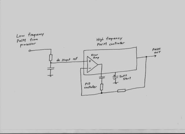 Cheers, �Tony. |
||||
| Solar Mike Guru Joined: 08/02/2015 Location: New ZealandPosts: 1123 |
Thank's, that's interesting, will keep that idea in mind. Actually I realized it would be better to give fine (changing) output voltage control back to the TL494, rather than the cpu have to continually keep modifying its low speed pcm duty cycle. To do this the cpu sets the initial reference voltage for the TL494 to 2.5v by setting the duty to 50%. The TL494 then autonomously modifies the output duty % to keep a constant voltage. The output voltage set point is modified adhoc by the cpu by moving the reference setting as required. See changes to circuit of "U6" 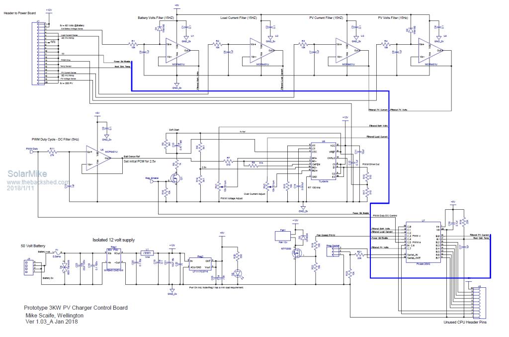 |
||||
| Warpspeed Guru Joined: 09/08/2007 Location: AustraliaPosts: 4406 |
I think you are quite right about making the power board be able to work by itself. There are many reasons for that, including the possible explosive effects of a software crash if you decide to do some software tweaking later on. Just thought I would mention the PWM driving PWM idea, it tracks so remarkably well its a trick worth remembering. Cheers, �Tony. |
||||
| Solar Mike Guru Joined: 08/02/2015 Location: New ZealandPosts: 1123 |
Have made some progress on a controller board, just about to etch one and do some testing. 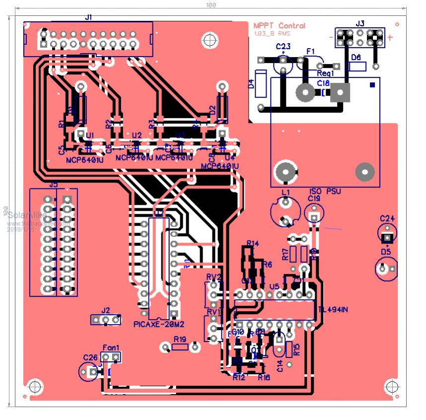 The power board really needs a second IRFP4668 in parallel with the main buck mosfet, if I want to operate it ao 100kHZ the switching losses start to add up, reducing the current in each device by 1/2 will make things nore efficient, so might do this and at the same time drive the fets from TC4452 chips direct from a PicAxe 28X2 running at an over clocked 80 mHZ; those Tip 41c/42c complementary driver buffers are not that fast at switching and will add to the power losses in the mosfets. Lets see if I can blow the current design board up first. Cheers Mike |
||||
| Zibe Newbie Joined: 15/01/2018 Location: AustraliaPosts: 10 |
Looks great, You wouldn�t believe it but I have built almost the same thing about a year ago. It however, is a fair bit smaller, 10*10CM. Some suggestions: � You can do MPPT with just the output current combined with input voltage. � I found a good old IR2110 driver was sufficient, cheap and available. I didn�t need to use any additional transistors for the MOSFETs. � Consider measuring the MOSFET temperature. Well done. |
||||
| Solar Mike Guru Joined: 08/02/2015 Location: New ZealandPosts: 1123 |
Hi Zibe, thanks for the comments. Mosfet temperature taken care of; sensor is already on the main control board. Unfortunately IR2110 drivers are unsuitable for driving parallel combinations of the mosfets used in this design for a number of reasons; they cannot supply sufficient current to switch quickly enough at 100 kHZ, so an additional current buffer stage is required, would like to move to 150 kHZ to keep the inductor size down, the buffers I have used could be better, will sort this in the new design by using TC4452's as buffers. A specific 1/2 bridge driver chip as used here is better suited in this instance as only a single pwm input signal is required and it has programmable dead time. I agree only a single current sensor is required for mppt, may do away with the input one. Am also looking at driving the power board mosfets from the 1/2 bridge HPWM output of the PIC cpu, however at startup the HPWM outputs do some crazy timing in starting up and not guaranteed to start cleanly, so additional shoot through switching protection is required, could use some NAND gates or 2 small mosfets here, I notice some of the Chinese EGS SPWM driver boards have a couple of pairs of transistors to do this, some dont, I know which ones I would be using. Cheers Mike |
||||
| Warpspeed Guru Joined: 09/08/2007 Location: AustraliaPosts: 4406 |
Providing effective shoot through protection can be a very big problem, especially where there can be several different power supply rails that can rise and fall independently at both power up and power down. Things can momentarily go nuts or get into dangerous states. I came up with this idea for my own multistep sinewave inverter. I am using half bridge power stages across +/- 220v dc supply rails. Even momentary cross conduction and its *bang* for sure. I use HCPL 3120 opto isolated gate drivers that have under voltage lockout on the isolated gate driver side. The driver leds are connected in INVERSE parallel and its simply impossible for both leds to be on together whatever else happens. 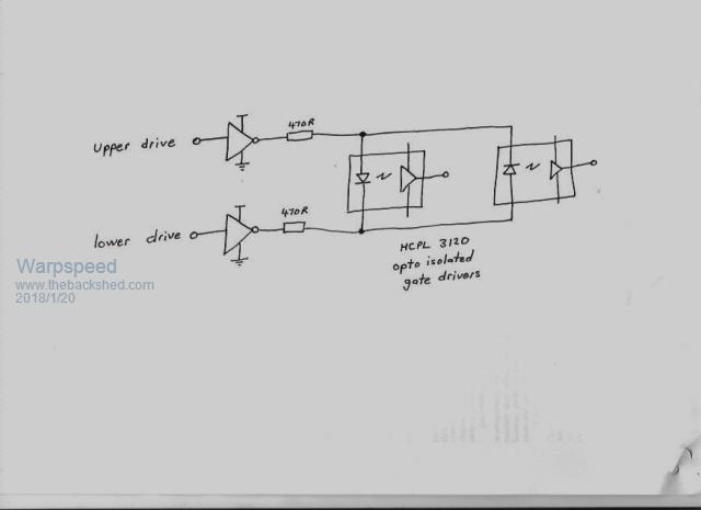 Cheers, �Tony. |
||||
| Solar Mike Guru Joined: 08/02/2015 Location: New ZealandPosts: 1123 |
Well its been some months since working on this project, after further looking at the PV requirements, its very feasible to go with straight pwm switching, assuming I can still purchase the 30V panels at the right price. In hind-sight the original design could be improved and built using a more modular architecture; If I treat this project in a similar way to the 10 Kw inverter and construct a number of mix and match boards, I can use them to either construct a simple pwm charge controller or a full mppt variant, depending on the PV requirements. To that end the PWM main switching board has been up rated to 150 amps, components can be optional depending on the max PV current. The second board contains the synchronous buck switch components and can be turned into a full MPPT device just by bolting it to the main switcher board. The third board connects to either the PWM or Buck boards for current and voltage sensing, the synchronous switch reverts to asynchronous operation at low charge currents to prevent very low duty cycle operation causing reverse power spikes that could cause considerable damage. Main PWM Module: 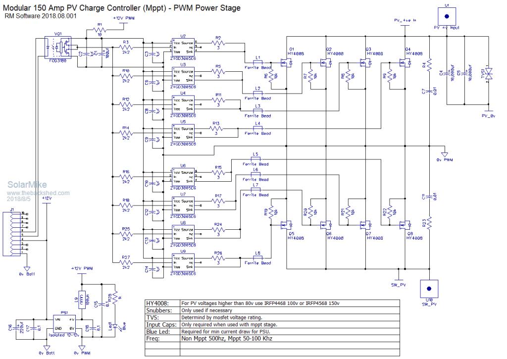 Buck Module: 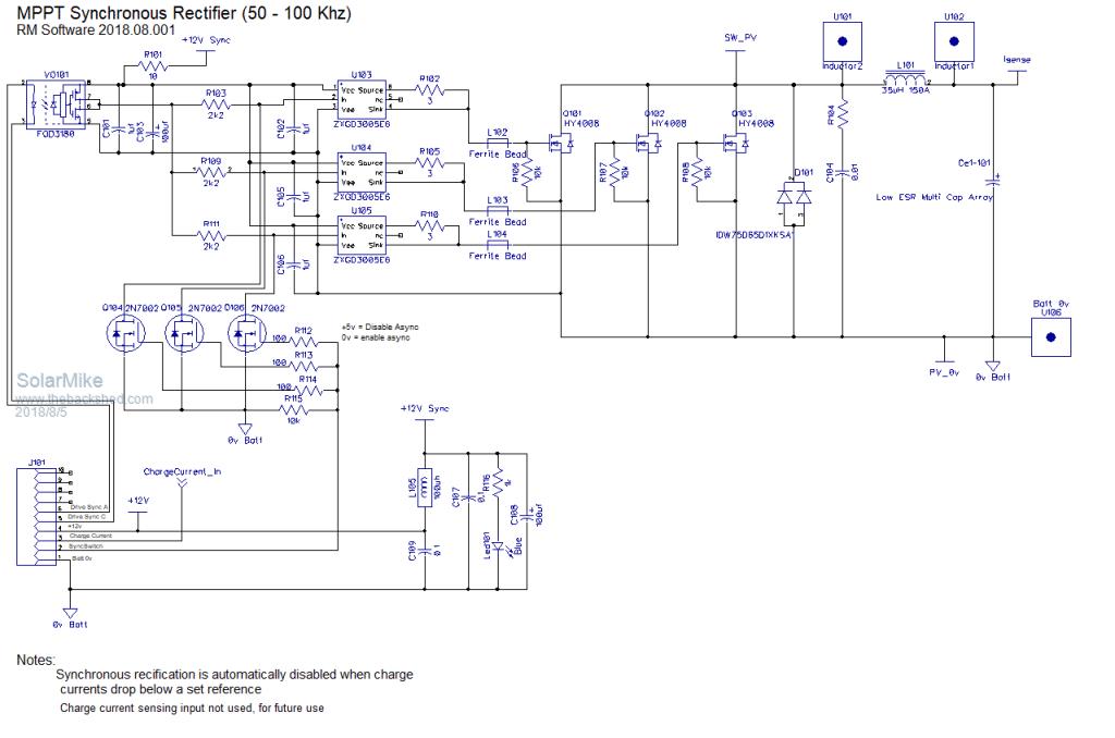 Sensing Module: 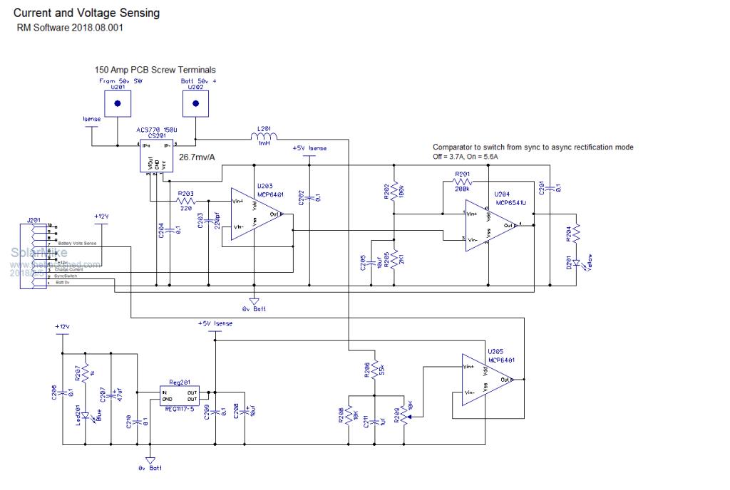 Drive board module has been prototyped, yet to draw it up... more to come. Cheers Mike |
||||
| Warpspeed Guru Joined: 09/08/2007 Location: AustraliaPosts: 4406 |
That is going to be quite a monster. Looking really good Mike. Cheers, �Tony. |
||||
| Solar Mike Guru Joined: 08/02/2015 Location: New ZealandPosts: 1123 |
I agree Tony it might be a monster, but hopefully manageable, in that some components can be left off if not required. Changes to the sensing board: Addition of anti-aliasing low pass filters for battery and PV voltage measurement and temperature control sensing. Hopefully this part is now sorted, driver next, unfortunately it will have an associated CPU but this could be any type as most of schematic will be analog - logic components, CPU functionality will be limited to mppt voltage settings etc, display and alarms, the basic controller will be able to be tested/setup with no CPU installed; that's the intention anyway. 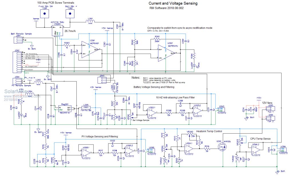 Cheers Mike |
||||
| Solar Mike Guru Joined: 08/02/2015 Location: New ZealandPosts: 1123 |
OK, here is a first cut of the PWM driver, suitable for either the PWM only module or the combined MPPT. Because I want to use 50-100 khz pwm on the MPPT module, most of the common cpu's don't have enough granularity resolution for setting the pulse width, ideally full 10 bit ie 0 to 1023 should be available; most can only do this only at much lower frequencies ( I stand to be corrected here... ). A 32 bit cpu would be ok to use, but I don't have any to play with. The schematic allows a lower frequency PWM be used by converting a PWM drive input to a voltage control of a PWM generator chip, the chip requires 0 to 1 volt input for 0 to 100% duty cycle at any carrier frequency to 2 Mhz, the frequency is easily set by 3 resistors. For dead time I have opted for some common logic that allows both delays be set independently when measured at the final end point, ie at the power mosfet gates. For non MPPT use, the synchronous rectifier module is not used and only a single output from the drive module, the PWM frequency can be set much lower eg 1Khz by altering the frequency setting resistors. Guess any suitable CPU could be used for controlling this, I have a bunch of PicAxe's here gathering dust, so will use a 20pin type. 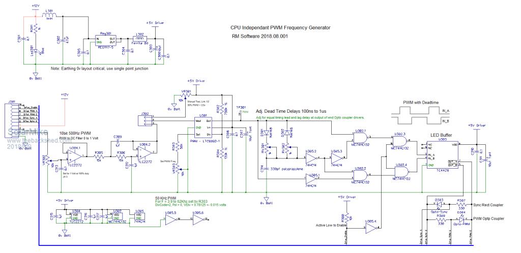 Cheers Mike |
||||
