
|
|
Forum Index : Solar : Build a Mppt 3 Kw Charge Controller
| Author | Message | ||||
| Warpspeed Guru Joined: 09/08/2007 Location: AustraliaPosts: 4406 |
Have to agree Mike. I am using one of the larger through hole Hall sensors myself, but for measuring much lower current by fitting a multi turn coil through the hole. A fifty amp rated sensor with five turns is perfect for measuring ten amps. If later on I change my mind, I can have any measurement range I want by simply adding or removing turns without changing the sensor. Cheers, �Tony. |
||||
| Solar Mike Guru Joined: 08/02/2015 Location: New ZealandPosts: 1129 |
Yes if size isn't an issue then the contact less ones as suggested are better. I have ordered a couple of these Sensors , they are reasonably small and seem good value; but require +- 12 or 15 volts supply, the center hole is 10mm x 20mm, there are lots of others out there with larger sized apertures, perhaps better suited for multiple turns. Will make another pcb for the other devices when they turn up, as will require something to measure the battery load currents which in my case will be around 300 amps. Cheers Mike |
||||
| Warpspeed Guru Joined: 09/08/2007 Location: AustraliaPosts: 4406 |
The +/- split supply type of Hall sensors are better in one respect, the output voltage is ground referenced, and zero measured current equals zero output voltage. Most have a 1,000 turn winding so that say, 50 measured amps = 50mA output. That 50mA may be sourced from the +ve dc supply only. The negative supply will only need to source a very few milliamps, and that minimal supply current never changes. The negative dc supply can come from a very low power charge pump circuit such as an ICL7662, so its not a big deal. Fitting multiple turns is not usually a problem because a lower measured current that requires a multiturn winding can use thinner wire in proportion anyway. For me it has been a good solution for lossless fully isolated current measurement with a very stable zero point. Single supply Hall sensors are easier to power up, require much less supply current, but will probably require a zero adjustment potentiometer somewhere, which is an inconvenience and one more thing to worry about. Cheers, �Tony. |
||||
| Solar Mike Guru Joined: 08/02/2015 Location: New ZealandPosts: 1129 |
Correct, but when measuring charge and discharge currents with the same device, +- supply types have a -ve below 0 voltage for discharge currents, which has to be transformed to a +ve above 0v value for measuring with an A-D converter in the cpu etc, so trade-offs everywhere as far as extra pots and circuitry required. Zeroing output at 1/2 rail volts (2.5v) for 0 sensor current will be required, unless two devices are used; guess at US$10 each its cost effective to do that. Mike |
||||
Madness Guru Joined: 08/10/2011 Location: AustraliaPosts: 2498 |
Mike have you played with a ADS1115 they are very useful for getting high resolution and handles + & - values. There are only 10 types of people in the world: those who understand binary, and those who don't. |
||||
| Solar Mike Guru Joined: 08/02/2015 Location: New ZealandPosts: 1129 |
Hey, no I haven't, but that chip with its differential mode maybe ideal for what I need. Most CPU's have an I2C interface now, so that isn't an issue. Cheers Mike |
||||
| Madness Guru Joined: 08/10/2011 Location: AustraliaPosts: 2498 |
It's the ducks nuts for the job plus you get other inputs as well to get high resolution for your battery voltage as well. You can buy them for about 1/3 of Adafruits price from Aliexpress. There are only 10 types of people in the world: those who understand binary, and those who don't. |
||||
| Solar Mike Guru Joined: 08/02/2015 Location: New ZealandPosts: 1129 |
More progress on the synchronous rectifier module: Mosfets mount on an alloy 30x30x6mm right angle as input from the power pwm switch module, no insulators, copper bars bolt to underside bottom end of pcb for +ve output and current sense module, copper bar bolts to source connections mid of pcb as 0volts rail, 12 x 820uf low esr caps used for filtering. Main 35uh inductor bolts from top to bottom of the pcb. IR1672 synchronous controller chip controls the on period of the parallel mosfets for synchronous rectification autonomously of the pwm power stage, so in theory the module could be retro-fitted to any pwm controller to make a mppt controller, with a suitable software change. 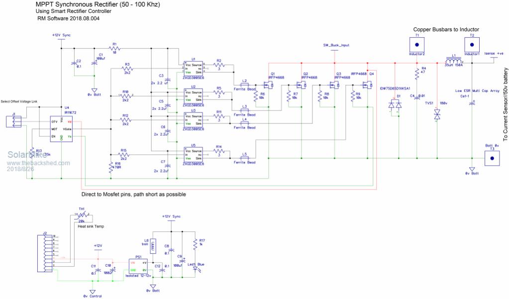 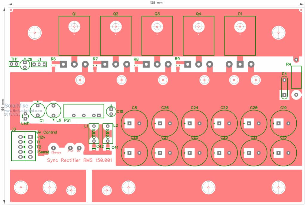 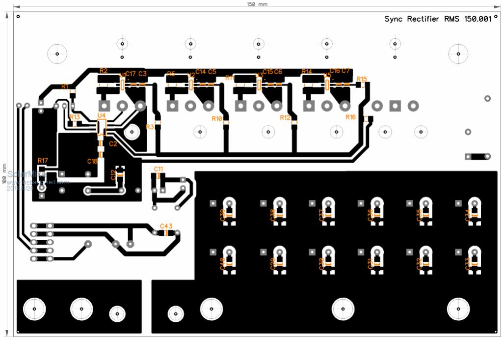 Its going to be fun making these prototypes, some of the traces are quite small. Edit: C9 has to be moved, its too far away from main 0v rail. Cheers Mike |
||||
| Solar Mike Guru Joined: 08/02/2015 Location: New ZealandPosts: 1129 |
Have made adjustments to the pwm driver schematic, now that the synchronous rectifier is autonomous and has no requirement for a dead-time controlled signal, the driver design can be simplified. The rational for using this driver is to allow 1024 or 10 bit resolution of the pwm output at any frequency, ie. 50 to 100 khz range, unless I go for an exotic cpu this isn't really possible direct from the cpu output. Instead we use a drive frequency that the cpu timers can easily generate with full resolution, generally around 1 - 3 khz is fine. The driver converts the input pwm duty cycle to a voltage between 0 - 1 volts and applies this to a precision pwm modulator chip, by changing a couple of resistors any frequency between 60 hz to 1 mhz can be output. The higher the pwm frequency, the smaller the buck converter choke, of course higher switching losses also occur, thus the suggested max of 100 khz. For mppt operation an extra logic input is provided to enable the static PV isolation mosfets, when only pwm is used (no mppt) the drive signal has a link on the totem driver chip to allow for this mode. 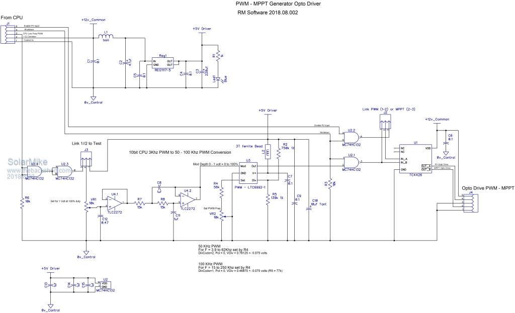 Cheers Mike |
||||
renewableMark Guru Joined: 09/12/2017 Location: AustraliaPosts: 1678 |
Good work Mike, do you plan to make boards available when finished? Would this mppt work down to 90v? Cheers Caveman Mark Off grid eastern Melb |
||||
| Solar Mike Guru Joined: 08/02/2015 Location: New ZealandPosts: 1129 |
Yes, will post final pcb gerbers here when its all working, the mppt function which is software dependent will work as long as the PV voltage > battery by a reasonable margin. Cheers Mike |
||||
| renewableMark Guru Joined: 09/12/2017 Location: AustraliaPosts: 1678 |
Good stuff, mine is 48v batt and would run 3 in series for 90v. Cheers mate Cheers Caveman Mark Off grid eastern Melb |
||||
| Solar Mike Guru Joined: 08/02/2015 Location: New ZealandPosts: 1129 |
Ok, have reached the point where I need some processing capability to start testing some of these modules; have quite a few Picaxe chips floating around looking for a project or two, micro-mite also looks like a great option, will have to get one to play with, Arduino would also be a candidate except have never used one before. So will start with what I know first, the Picaxe chips all have different pin outs for similar port configuration IO, so what I want is an adapter pcb that has a standardized set of IO pins and a piggy-back socket to plug the pic into, then I can mix and match various chips without having to do a pcb re-design. Have come up with these 3 pcbs that take Picaxe 14M2, 18M2+, 20M2. 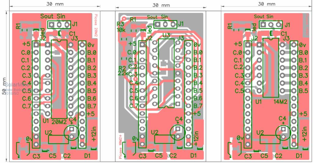 Would have thought these or similar would be readily available, not so... Cheers Mike |
||||
| Madness Guru Joined: 08/10/2011 Location: AustraliaPosts: 2498 |
I have code ready to go if you want to try Arduino. There are only 10 types of people in the world: those who understand binary, and those who don't. |
||||
| Solar Mike Guru Joined: 08/02/2015 Location: New ZealandPosts: 1129 |
I might take you up on that offer Mad, will get it running with PicAxe basic first, then porting it over to Arduino would be a great learning exercise and will perhaps suit others here who want to build it with their own code. Right so this 3 - 7.5 KW controller is still rolling along, to keep with the modular design concept, have made the CPU adapter boards above, and the MPPT PCB, next to etch is the synchronous rectifier PCB and Mppt driver interface PCB. For the Mppt driver board, have made it a plugin PCB, that will with right angle connector plug in to a mother board hosting the CPU and IO sensing/display boards. Input signals are 0v, +12v, PWM drive from CPU, Enable PV, Shutdown; outgoing connections are the 2 x 12 volt opto-coupler drive signals. I may have gone over-board a bit on the small chokes used in all these designs, the PWM oscillator chip puts out a huge amount of RF hash, thus the ground planes and small ferrites. Theory being that if the design requires changing - most likely will - then a re-design of a huge complex main board wont be required, bit like how we write software, break it down into manageable testable modules. 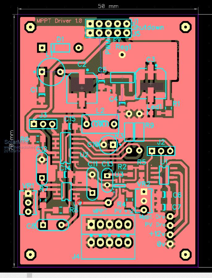 Cheers Mike |
||||
| Solar Mike Guru Joined: 08/02/2015 Location: New ZealandPosts: 1129 |
Who would have thought controlling the speed of some fans would be so temperamental, I did try the circuit used in the OZInverter and that works, but it doesn't fit with my design requirement. I need to read the various heat-sink and air temperatures using the PICAxe and make decisions based on the measurement, one of these being to vary the fan speed proportional to temperature, normally I would use a DS18B20 1-Wire device, but using this slows down the PIC to 4 MHz, normally running at 32 MHz and this stuffs up the PWM outputs that are controlling the MPPT switching. Have opted for a LM35 (10mv/degreeC), that works well and seems pretty accurate, allowing the cpu to run at full speed. Those 2 wire 120 - 140mm 12v fans don't like being PWM'd, they make strange noises, so have designed the circuit below, a 7 KHz pwm is input, converted to a voltage to vary the speed in a smooth manner from stopped to full speed, the last op amp drives the mosfet in a linear mode by sensing the fan current using a 1R resistor, for 2 parallel fans use 0.5R If anyone has a better solution, please let me know. 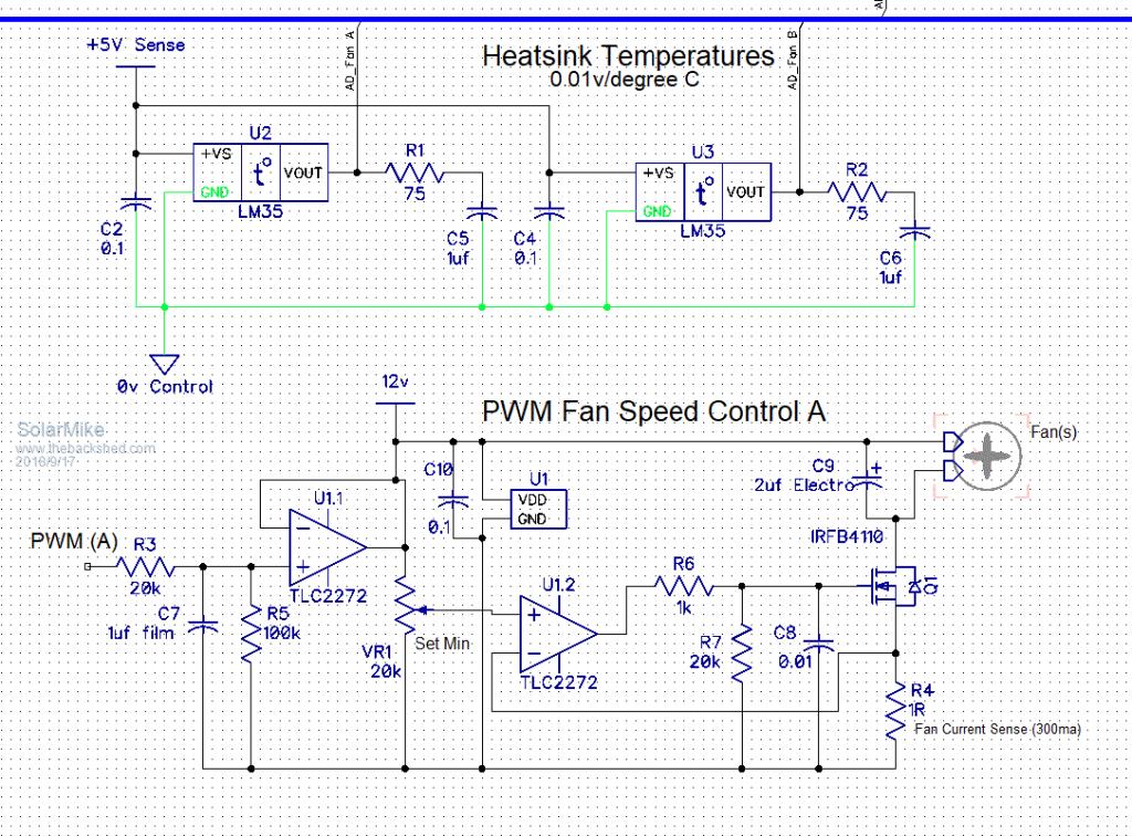 Cheers Mike |
||||
| Warpspeed Guru Joined: 09/08/2007 Location: AustraliaPosts: 4406 |
Those brushless dc fan motors definitely need a stiff steady dc supply which could be provided by a decent sized electrolytic directly across the motor. You should then be able to PWM the power into the electrolytic via a choke in the usual way. I would expect that to require a reasonably high voltage to start the fan turning, but it may then run faster than you may wish for. Many of these brushless fans have a third wire which is a tachometer output from the commutator position sensor. This may require two control loops, a slow outer loop for actual temperature sensing, and a faster responding inner loop using the fan tachometer as an input. Fan voltage would then ramp up to get the thing moving initially, then ramp back down to hold some required rpm demanded by the temperature control loop. Its complicated, but I can see that low speed operation may be a bit erratic otherwise. Cheers, �Tony. |
||||
| renewableMark Guru Joined: 09/12/2017 Location: AustraliaPosts: 1678 |
I don't have a clue how it works but the mad arduino software runs two sets of fans independantly and will vary the speed. Code is top of p43 Cheers Caveman Mark Off grid eastern Melb |
||||
| Solar Mike Guru Joined: 08/02/2015 Location: New ZealandPosts: 1129 |
Agree, would be better if I had 3 wire fans, however the above cct works well, vary the duty cycle from 70 (very slow) to 400 (full speed) Cheers Mike |
||||
| Madness Guru Joined: 08/10/2011 Location: AustraliaPosts: 2498 |
I use PID to control the fan speed so as the temperature rises and triggers the fan to start the PID will ramp up the PWM until the temperature is reduced. This overcomes the starting issue as the temperature only has to rise slightly above the set point and fan speed will increase to 100%. There are only 10 types of people in the world: those who understand binary, and those who don't. |
||||
