Notice. New forum software under development. It's going to miss a few functions and look a bit ugly for a while, but I'm working on it full time now as the old forum was too unstable. Couple days, all good. If you notice any issues, please contact me.
Tinker Guru Joined: 07/11/2007 Location: AustraliaPosts: 1904
Posted: 08:36am 19 Jun 2018
Copy link to clipboard
Print this post
You are doing very well here tinyt.
Its interesting to see how different people do things differently. I wound my toroids with the wire coming 'up' from the hole, found that worked for me, doing it left handed.
What did you do at the inside of the bicycle rim to stop the spoke holes scratching the wire? I did not have a bike rim handy so used black poly tubes, slit to get the wire in & out. That was nowhere near as rigid as your rim, used lots of tape to keep it together
You may not have read a tread on toroid winding, posted some time ago, where it was suggested to arrange the wires on the outer rim of the toroid in pairs. This has the advantage in subsequent layers, where the next 'pair' locates in the gap of the layer below. Of course. through the hole all wires are side by side to fit the maximum turns.
So, it only requires one marking on the circumference for the wires to lay neatly radially, all the following layers fall in place automatically for a neat spacing.
Keep up exercising those finger & arm muscles you did not know you had .Klaus
tinyt Guru Joined: 12/11/2017 Location: United StatesPosts: 431
Posted: 01:48pm 19 Jun 2018
Copy link to clipboard
Print this post
Thanks for the complement Klaus.
Yes, I noticed the machining burrs on the spoke holes when I was dis-assembling it. So I filed them smooth, round file on the spoke nut heads side and flat file on the spoke wires side. Then I used masking tapes on both surfaces (you can see the masking tape covering the spoke holes nut heads side in an earlier picture where I was loading the bike rim). After applying the tapes, I cut the rim and then filed the rough edges of the cut. After the rim is inserted through the toroid, I used masking tape to keep the cut ends together.
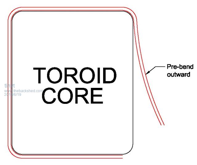
I "discovered" that if you pre-bend the wire outward prior to laying on the flat surface of the toroid, it will no bulge outwards.
I will keep the wire pairing in mind next time, if there is one.
After this I think my fingers will no longer be rheumatic and maybe nimble enough to play the piano. LOL Edited by tinyt 2018-06-21
Madness Guru Joined: 08/10/2011 Location: AustraliaPosts: 2498
Posted: 09:17pm 19 Jun 2018
Copy link to clipboard
Print this post
The aluminium bike rime I use has a hollow lip that I was able to insert some wire in with a bend so about 30mm protrudes. Then the other end slips over those wires and makes it very rigid.There are only 10 types of people in the world: those who understand binary, and those who don't.
tinyt Guru Joined: 12/11/2017 Location: United StatesPosts: 431
Posted: 11:06pm 19 Jun 2018
Copy link to clipboard
Print this post
Finally got the first 115vac layer wound. It takes 118 turns to make the turns per volt the same as the half of the existing original 230vac inner layer. With 115vac applied to half the existing winding, the voltage difference vs the new layer is only 10 millivolts. Idle current is 0.093 volts or 115 x 0.093 = 10.7 watts. I wish it is lower.
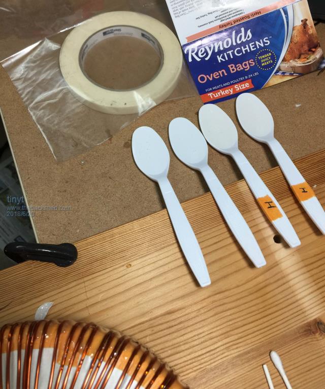
Started epoxy. I used disposable spoons for measuring. Did not have paper cups, so I used whatever is available for mixing (poly bag sheets and Q-tips).
Warpspeed Guru Joined: 09/08/2007 Location: AustraliaPosts: 4406
Posted: 11:28pm 19 Jun 2018
Copy link to clipboard
Print this post
Ten watts is actually pretty good for a transformer of that size.Cheers, �Tony.
johnmc Senior Member Joined: 21/01/2011 Location: AustraliaPosts: 282
Posted: 12:27am 20 Jun 2018
Copy link to clipboard
Print this post
I am watching your build,well done. cheers johnjohnmc
tinyt Guru Joined: 12/11/2017 Location: United StatesPosts: 431
Posted: 03:06am 20 Jun 2018
Copy link to clipboard
Print this post
I guess I have a slight advantage of living where the power frequency is 60Hz.
I connected all three 115vac windings in parallel and idle current is 0.097 amp or 115 x 0.097 = 11.15 watts. Luck is still with me.
tinyt Guru Joined: 12/11/2017 Location: United StatesPosts: 431
Posted: 04:23am 20 Jun 2018
Copy link to clipboard
Print this post
Thanks, will post as much info as I can.
tinyt Guru Joined: 12/11/2017 Location: United StatesPosts: 431
Posted: 04:36am 24 Jun 2018
Copy link to clipboard
Print this post
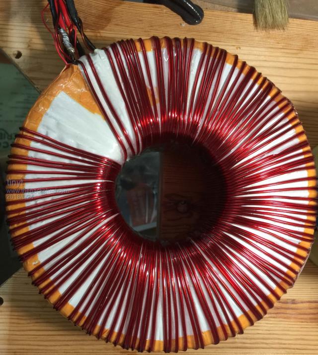
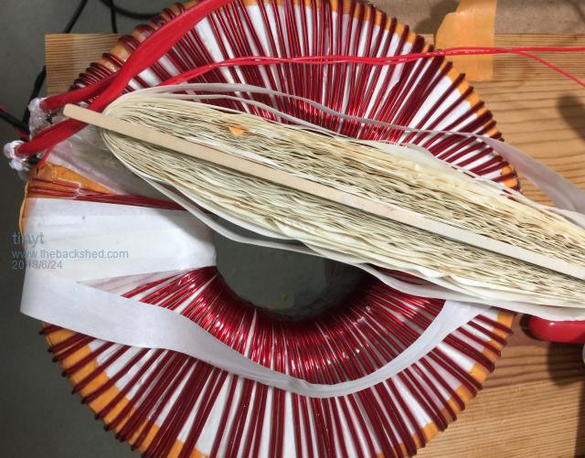
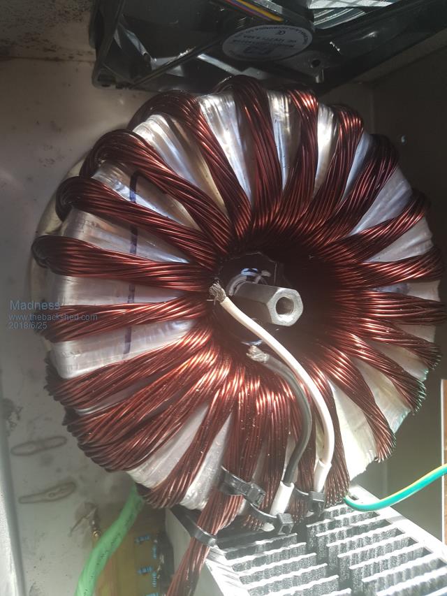
Just a photo gallery:
Here the first added 115vac winding is already covered with the insulating tape. The epoxy I used in that winding is a single thin coat of a thinned down regular epoxy. I then added a 12vac winding. The wire is too thin (awg #26) but that is what I have. I then varnished it and then covered it with insulating tape.
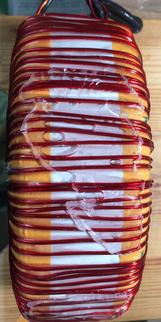
Here is the second added 115vac winding. Same awg as the first, but the 118 turns still fit in the toroid ID with room to spare. The wire is softer than the earlier one I used, so I was able to pull tighter together.
Since there is a gap in the winding, I might as well use it. Was able to buy awg #22 wire, so I added a second 12vac winding.
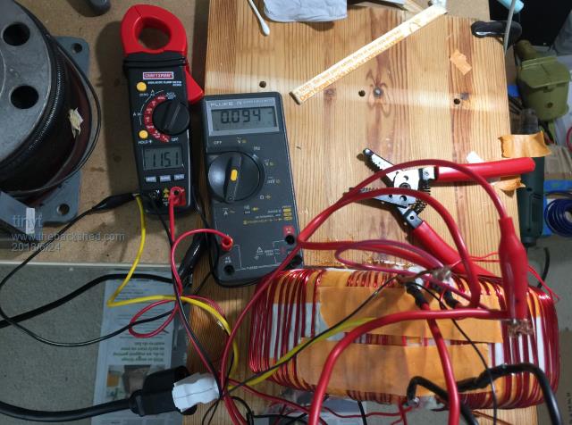
With all four windings in parallel, I measured the idle current at 115vac, still very close to the earlier measurement (0.093 amp.), 0.094 amp. I used series amp measurement with the fluke (10A range) instead of the clamp meter with its 40A range. I think it is more accurate.
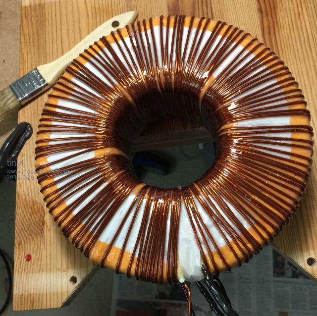
The boat epoxy came which is much thinner and that is what I used on this second added 115vac winding. I covered everything in one application, set it on the table to dry. The epoxy oozed down. Good thing I placed a poly sheet on the table, otherwise I would have ended with a boat anchor glued on the table. Next time I think I am going to hang it to dry.
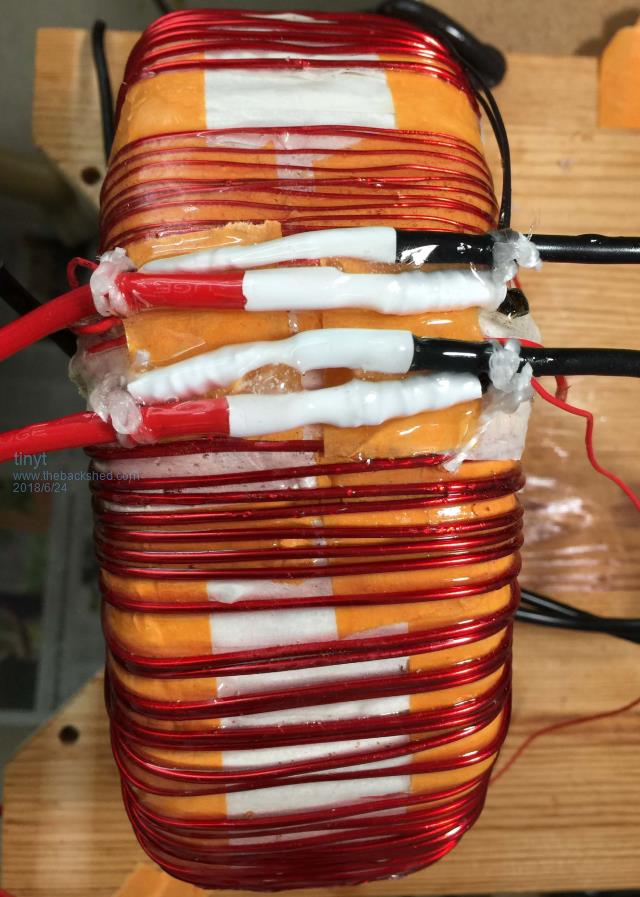
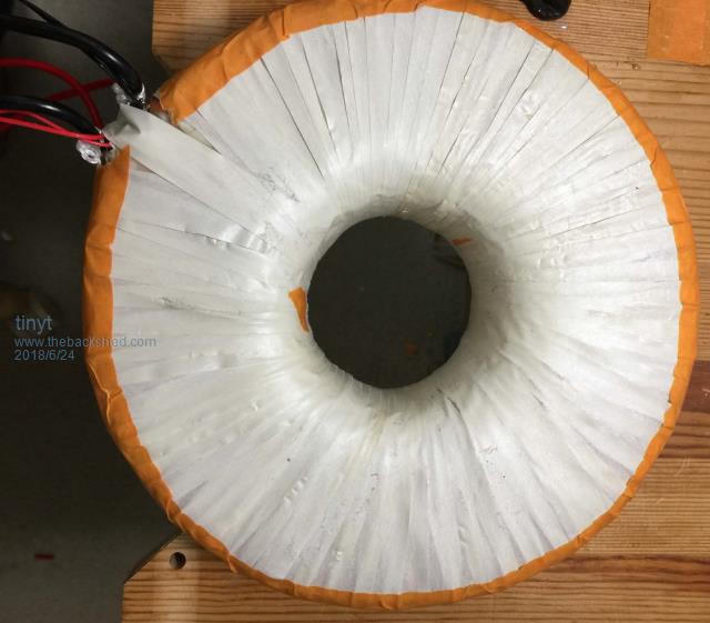
I now cleaned up the connections of the 115vac windings. The thinner magnet wire is the second 12vac winding. Flux was cleaned later.
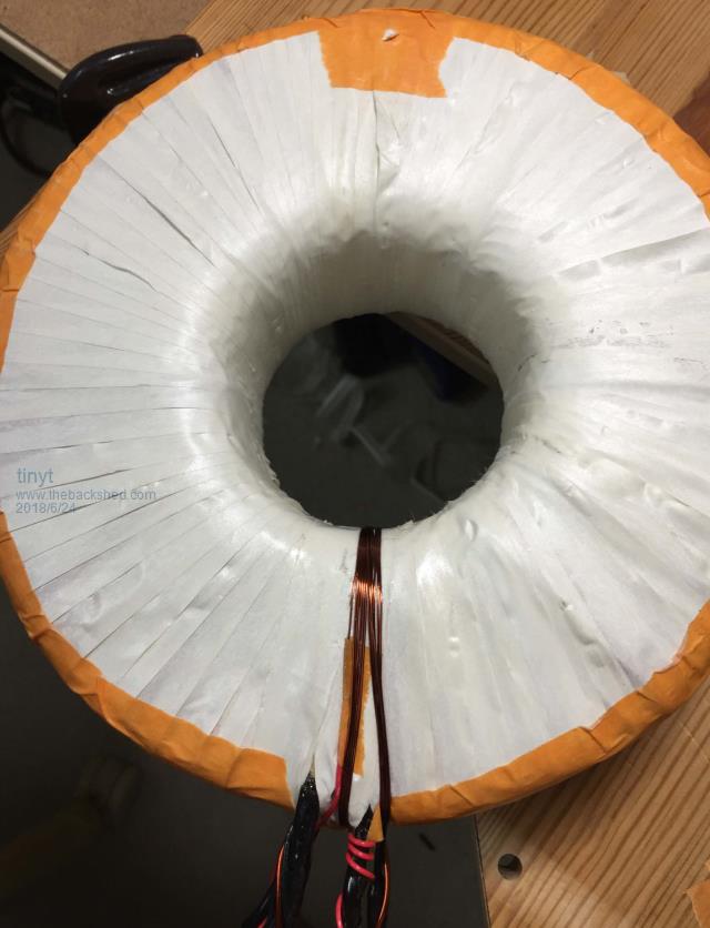
I now started covering with the insulating tape.
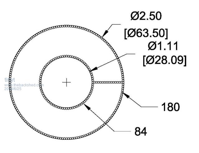
It is now ready for the primary. The ID now is about 2.5" (63.5 mm). I have to figure out what copper wire(s) to use and how to fit it. I think I will have to use multiple strands of small gauge soft annealed copper magnet wires.
Edited by tinyt 2018-06-25
tinyt Guru Joined: 12/11/2017 Location: United StatesPosts: 431
Posted: 08:10pm 24 Jun 2018
Copy link to clipboard
Print this post
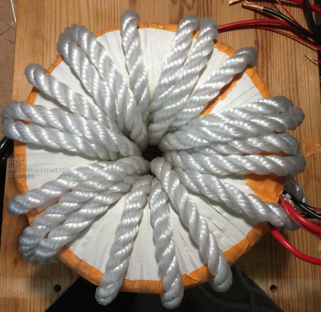
I have a 12.7 mm dia. rope and did a trial winding, I was able to fit 20 turns. This rope diameter is bigger than what I will need.
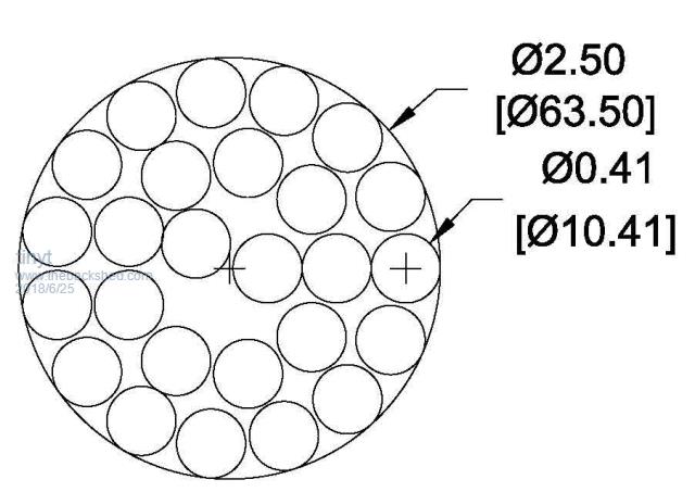
Doing some calculations: The secondary is composed of 4.17 mm sq. and 2.08 mm sq. wires giving a total of 6.25 mm sq. Using the 9:1 ratio, the primary should have 6.25 x 9 = 56.25 mm sq. I am waiting for my purchased 0.91 mm wire (0.653 mm sq.) to be used for the stranded primary. This requires 56.25 / 0.653 = 86 strands. For 26 turns there will be a total of 86 x 26 = 2236 strands inside the toroid. If the 86 strands were arranged in a perfect circle that is completely filled, the nearest number of strands is 91 with a circle diameter of 10.41 mm, this is rounding up the 0.91 to 0.94 mm strand dia. Drawing a polar array of these 10.41 mm strand groups inside the 63.5 mm inside diameter of the toroid shows that the needed 26 turns will barely fit under ideal conditions.
If the strands were evenly distributed inside the toroid, I will still have 28 mm dia. empty hole for the toroid mounting bolt. I think I will use this approach, and also no insulating sleeving on the strands. I will just have to make sure that all the strands will be covered by the boat epoxy.
Edited by tinyt 2018-06-26
Tinker Guru Joined: 07/11/2007 Location: AustraliaPosts: 1904
Posted: 09:01am 25 Jun 2018
Copy link to clipboard
Print this post
I do like your rope idea to test for number of turns space, very practical.
I feel sorry for you when you get to wrestle 86! strands into a neat round wire. That would be in the 'too hard' basket at my workshop. Good luck, I think you might need it And I'm looking forward to learn how you managed this task.
9:1 cross section area is the ideal value, most builds here are not very close to this. Those using insulated welding cable might get a 6-7:1 ratio. I think my double stack comes very close to 9:1 but there were less than half of your turns and I used 6 in hand of 15mm sq rectangular enameled winding wire for the primary. Klaus
Madness Guru Joined: 08/10/2011 Location: AustraliaPosts: 2498
Posted: 09:33am 25 Jun 2018
Copy link to clipboard
Print this post
9:1 Is do able Klaus, I have done it on a single core as well with home twisted wire. One key to it is to comb the wires out so they are all in parallel then I put small cable ties on to keep the bundle together until they are twisted. Once twisted remove the cable ties and fit a length of heat shrink over the wire and heat it. Works well but does require some grunting to get it twisted well.There are only 10 types of people in the world: those who understand binary, and those who don't.
Warpspeed Guru Joined: 09/08/2007 Location: AustraliaPosts: 4406
Posted: 09:56am 25 Jun 2018
Copy link to clipboard
Print this post
If you twist it when its straight, and then try to wind it around the toroid, you may be in trouble. Wires on the outside of the bend will be a bit short, and wires on the inside of the bend may buckle and bulge outwards.
May be best to keep the wires parallel and wind it on like that. Each wire will assume some kind of radius around each bend, and the wires can slide over each other and be happy. Heat shrink will then bind the whole thing together in a neat bundle.
See how this goes, but I have not had a lot of success with really large twisted bundles of wires.Edited by Warpspeed 2018-06-26Cheers, �Tony.
Madness Guru Joined: 08/10/2011 Location: AustraliaPosts: 2498
Posted: 10:44am 25 Jun 2018
Copy link to clipboard
Print this post
If they are not twisted they want to flatten out at the corners and take up a lot more space preventing getting enough turns on. When they are twisted it holds them together and different wires get to go around different radiuses sort of randomly. My own experience is that it works when twisted. There are 24 turns on the primary below and 9:1 ratio in turns as well as total wire cross-section. Also they all fitted snug against the inside of the core leaving plenty of space for mounting.
Edited by Madness 2018-06-26There are only 10 types of people in the world: those who understand binary, and those who don't.
tinyt Guru Joined: 12/11/2017 Location: United StatesPosts: 431
Posted: 05:34pm 25 Jun 2018
Copy link to clipboard
Print this post
Klaus, the rope trial winding also gives me a rough estimate of how long the winding will be (about 780 cm. + lead outs). The wire size I picked is much thinner than what I see being used here, still it needs to be 86 strands. Like Tony suggested, I don't intend to twist them into a round bundle. Will post picture whether it is a success or failure.
I like Gary's use of cable ties to secure the lead outs and use of a stand-off(long nut?) instead of a mounting bolt.
Warpspeed Guru Joined: 09/08/2007 Location: AustraliaPosts: 4406
Posted: 08:25pm 25 Jun 2018
Copy link to clipboard
Print this post
Beautiful work there Mad, and I believe Mark made a splendid job of his too.
It can certainly be done, but much depends on the number of wires in the bundle, and their thickness, and the total length of wire required. It does become a lot more difficult beyond a certain point.
Cheers, �Tony.
Madness Guru Joined: 08/10/2011 Location: AustraliaPosts: 2498
Posted: 09:01pm 25 Jun 2018
Copy link to clipboard
Print this post
Soon I will be doing another bigger one with 37 X 2mm diametre wires.
That long nut is there for a bolt to screw through the top plate into it.Edited by Madness 2018-06-27There are only 10 types of people in the world: those who understand binary, and those who don't.
tinyt Guru Joined: 12/11/2017 Location: United StatesPosts: 431
Posted: 06:39am 26 Jun 2018
Copy link to clipboard
Print this post
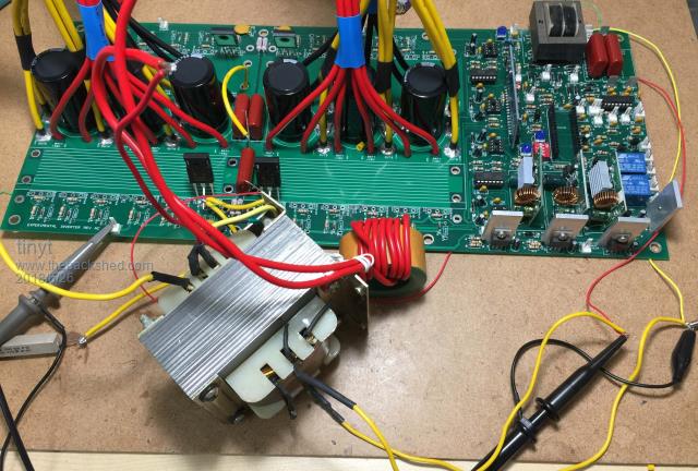
I have a small EI transformer that has 110vac primary and several secondaries. I was able to configure it for 26vac input and 115vac output. I used it for the first mosfet testing: Four mosfets, 10 ohm series resistor, bulk capacitors bypassed. 1.5 ampere power supply set to 54vdc. ICs on board are two IR2010s and one modified EGS002. The transformer has no load. See picture below.
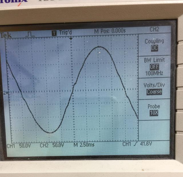
With the EG8010 SPWMEN at gnd, the current draw from the 54vdc is 0.01 amp. With the SPWMEN at +5vdc, the current draw is 0.18 amp. Connecting my old 'scope at the output, I get this screen picture. Note the often seen distortion near zero crossing.
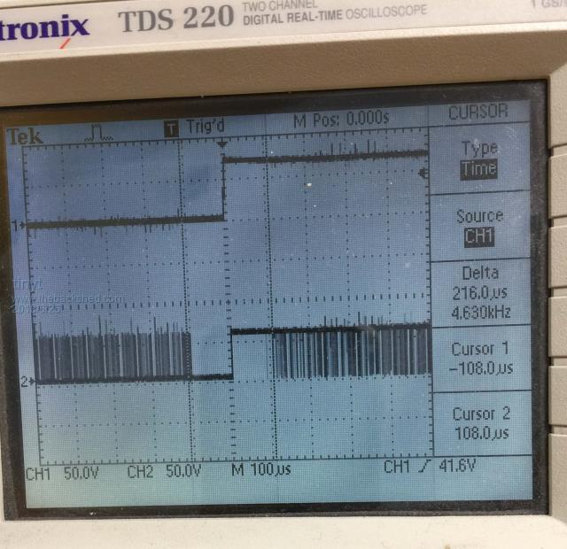
I attached CH1 probe to the fumdamental mosfet gate drive and CH2 to the junction of the mosfet SPWM output and series choke and I get this screen picture. Looks like the SPWM pulses starts and end 108 microseconds from the fumdamental zero crossing. I am guessing that this 'quiet' time is causing the distortion. I don't know about the distortion midway between peak and zero.
I have several surplus 54vdc 5 ampere power supplies I bought a long time ago, I need to look for them in my junk garage and see if I can use them for load testing. I think I need to buy the batteries now.
Madness Guru Joined: 08/10/2011 Location: AustraliaPosts: 2498
Posted: 06:44am 26 Jun 2018
Copy link to clipboard
Print this post
Well done, try changing the turns on your choke to see if that cleans up the 0 crossing blip.There are only 10 types of people in the world: those who understand binary, and those who don't.
wiseguy Guru Joined: 21/06/2018 Location: AustraliaPosts: 1000
Posted: 02:37am 27 Jun 2018
Copy link to clipboard
Print this post
Hi Tinyt great work so far & on your toroid wind. Does altering the VFB trimmer change the 108usec gap timing relative to the fundamental zero ? (ignoring change in Vout) Would love to know - still waiting impatiently for my EGS002 boards.....If at first you dont succeed, I suggest you avoid sky diving.... Cheers Mike


 .
.