
|
|
Forum Index : Electronics : another inverter project
| Author | Message | ||||
| Warpspeed Guru Joined: 09/08/2007 Location: AustraliaPosts: 4406 |
A few points to ponder... If you connect up a pwm inverter with little or no series choke, the transformer voltage waveform will follow fairly closely the desired sine wave shape. The output waveform should look quite reasonable. The big disadvantage of this will be the HUGE peak currents through the mosfet bridge. Every time it switches it has to charge and discharge all the capacitance of the transformer and any additional capacitance that you have connected across the secondary, through a very low series impedance. While this can and often does work, it will be very stressful for the mosfets. So people say "never fitted a choke and my inverter works fine". I really cannot argue with that. As you add more series choke inductance, the switching peak current spikes greatly reduce, and the mosfets work under much less stress. But adding series impedance between the switching bridge and the transformer tends to decouple the transformer from the pwm drive waveform slightly. The transformer then tends to do its own thing with regard to any self resonances or core saturation problems. So we may start to see wiggles and bumps on our waveform. The natural reaction to that is that the big new high inductance choke is bad because it creates all this new waveform distortion, and its not an improvement. We have fixed one problem (the huge destructive mosfet killing current spikes) and replaced it with a different problem (waveform distortion). The solution is to keep the big choke and fix the problems that the transformer is creating at the transformer. The biggest problem with the transformer is the high voltage secondary winding which has a lot of capacitance down to the steel core because its one very wide layer. It also has a very high inductance, due to the massive core size and the high permeability of the really good grain oriented steel. This results in a low self resonant frequency in the low Khz region, something we can do nothing about. Harmonic distortion in our 50Hz can excite this resonance and create stationary ripples in the waveform. The more choke we add, the higher the amplitude of these ripples become. The solution surprisingly is to deliberately add more capacitance across the secondary and lower this resonance. The lower we go, the better the waveform becomes, but this introduces yet another problem !! This all assumes that the series choke is large enough to allow the adding of this extra extra capacitance. Without the choke, extra capacitance might kill our mosfets from lethal current spikes. Anyhow, as we tune our transformer resonance closer to 50 Hz, the wiggles go away, but we might find that the voltage feedback now has problems controlling the output voltage at light loads. There can be a massive buildup of resonant energy which can cause the voltage to run away beyond the ability of the feedback to control. There is a solution to that problem too... If the transformer is deliberately tuned to exactly 1.5 times the inverter frequency, any tendency to build up resonant energy is defeated by the stored energy being out of phase. Its a kind of magic self damping effect. So tune your transformer secondary to 75Hz +/- 1Hz (90Hz in America) and you will have a very clean waveform. There is another issue that is completely separate. Some people have observed a kink in the waveform at or soon after the zero crossing, but in one direction only. This appears to be transformer staircase saturation caused by the negative and positive half cycles not being of identical area. It could be due to many things, unequal pwm due to unequal delay in the gate drive circuitry, faulty pwm waveform due to software, or even unequal rds on of the upper and lower mosfets. The flux in the transformer ratchets up to saturation in one direction. Maximum flux is at the zero crossing point, not the voltage peak, so we see the effect at or soon after the zero crossing. There is not a lot you can do about it, so unless there is something seriously wrong, it can probably be ignored. So in summary: 1/ fit a big high inductance non saturating choke, which will probably introduce some distortion. 2/ tune your transformer to exactly 75Hz (90Hz in the US) to get rid of the distortion. Cheers, ĀTony. |
||||
| Warpspeed Guru Joined: 09/08/2007 Location: AustraliaPosts: 4406 |
Nick, I found some of those ferrite U cores in my junk drawer. And a couple of them already had 22 turn windings on them ! So I fitted up one U core with 22 turns and another U core without any turns and measured 2.16mH with zero air gap. My ferrite data book only has inductance figures for one U core and one I bar in combination of 6.2uH for one turn. 6.2uH x 22 x 22 = 3.0mH Two U cores have a lot longer magnetic path than a U and an I, and will produce much less inductance, so 2.16mH is probably about right. Anyhow, tried a 15mm gap and measured 110uH with just the one 22 turn winding plus one bare core. My data book only has Hanna curves for 20mm square cores and 30mm square cores, not the 25mm square cores. But even the much larger 30mm cores might be right on the limit to get to 120 amps at 50uH before saturation. If I draw a line between the two curves and assume that might be something like a 25mm square core set, then I squared L of 250mJ with a 5mm gap might be about the limit which may end up at about 71 amps saturation for 50uH. The data book is probably a bit conservative, but its going to saturate well before 120 amps even with a 15mm gap. Only way to know for sure would be to build a choke testing rig. 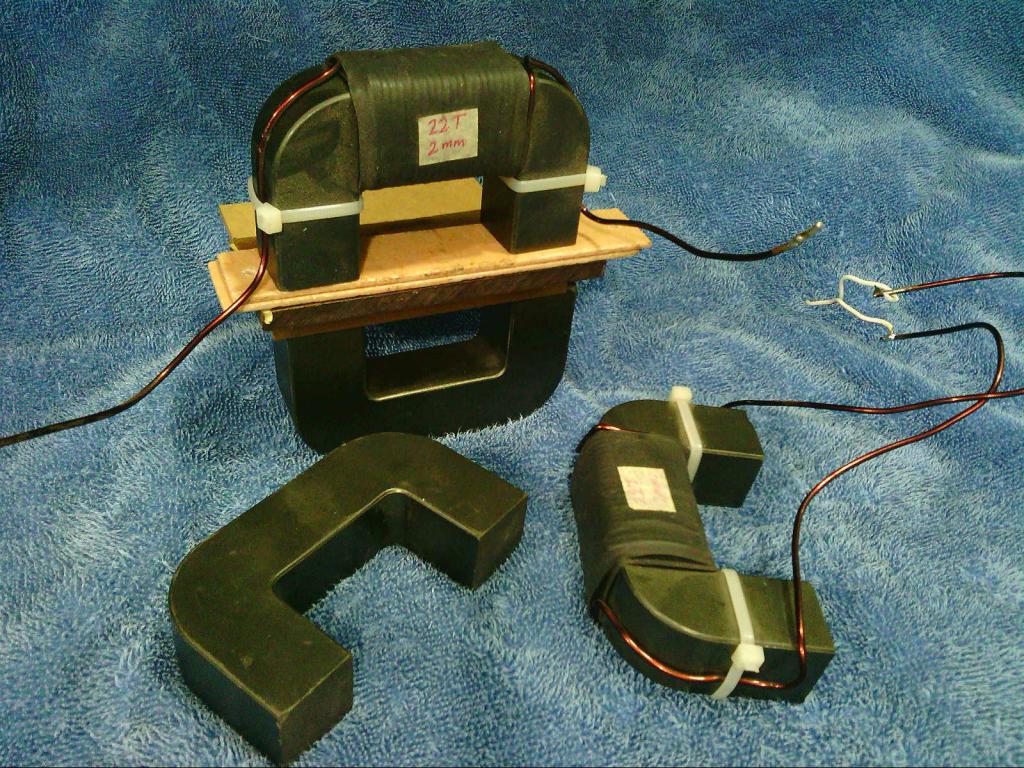 Cheers, ĀTony. |
||||
| Warpspeed Guru Joined: 09/08/2007 Location: AustraliaPosts: 4406 |
Ferrite is definitely the thing to use for high frequency transformers and chokes that operate at both very high voltages and very high frequencies. You will find that most commercial switching power supplies use a ferrite cored transformer, and a powdered iron toroid for the choke. Powdered iron is a lot cheaper, much more lossy, but can take a lot more ampere turns before saturation. Its the preferred material for chokes that operate at low voltages and very high dc current, even at very high frequencies. Now the twin evils we are trying to avoid in our choke are core saturation and excessive core heating. Ferrite saturates at around 0.3 to 0.35 Teslas. Powdered iron saturates at around 1 Tesla. Silicon steel about roughly 2 Teslas plus. So right away we see that steel can run about six times the dc ampere turns than with a ferrite core of the same cross sectional area. Ferrite is also very expensive in the larger sizes. Now we come to core loss, especially core loss at high frequencies. Core loss is composed of two parts, hysteresis loss and eddy current loss. Hysteresis loss is mainly frequency dependent, but is also flux swing dependent. It rises very steeply with frequency. Eddy current loss is also dependent on flux swing and frequency, and also rises steeply with frequency. We can burn up a choke from just core temperature rise by having both a large ac flux swings combined with a high frequency. Now a transformer works from flux swing to generate voltage in the secondary. That is inescapable. ĀSo a high frequency transformer MUST have an efficient core to do what it must do. On the other hand, a choke can be designed to have an absolutely minimal ac flux swing by using a relatively lot of turns, and a comparatively large core cross section. Now all of this depends on the current flowing through the choke. If its pure dc, core loss will be zero. All the heating comes from resistive heating in the wire. Imagine we had a choke of infinite inductance, the current would always be pure dc, no matter how high the applied ac voltage or the frequency. If our choke has enough turns, and enough core cross section, the inductance will be high enough to create a high Xl or inductive reactance. The ac ripple current could be very low, like 100mA rms with 50 amps of dc flowing. In fact as the frequency rises the inductive reactance rises too, and that can greatly offset the relative rise in core loss with frequency. Its perfectly reasonable to use a laminated steel core in a high frequency choke provided its large enough in core cross section and has ample turns. It would never work in a high frequency transformer though !! There is another bad effect of high frequencies, skin effect in the wire. This too is a magnetic effect where the alternating magnetic field forces current to flow along the surface of the wire. ĀAs with the core, we can build a high frequency choke with solid wire because the ac ripple current is very low, low enough to flow along the surface while the bulk of the dc current uses the entire wire cross section. Again, high frequency transformers are very different to high frequency chokes. Transformer windings at very high frequencies are often thin foil, or multistranded litz wire. Chokes can work perfectly well with solid round wire, because the choke predominantly carries only dc. Its the high frequency ripple current the choke is there to limit in the first place. If its designed and working properly, there should be very little ac component in the dc current the choke carries, so high frequency effects in both the wire and the core are nowhere near as severe as in a transformer. All the commercial inverters run steel or sometimes powdered iron chokes. Never ferrite its just not cost effective in the very large sizes that would be required for a high powered inverter. It would certainly work, especially if you can get the ferrite free. But a steel choke will do the exact same job at far lower cost and far smaller size. And that is what you will usually find in the larger commercial inverters, and sometimes powdered iron in the smaller commercial inverters. *edit* Here is a further thought. The choke is directly in series with the primary of the inverter transformer, and both carry the exact same identical current. Why is it that the choke must have a ferrite core, while the main inverter transformer can get away with a steel core ? Remember the current, and the magnetic effects produced by that current in the respective windings and cores will be the same in both. . Edited 2020-01-21 11:59 by Warpspeed Cheers, ĀTony. |
||||
| nickskethisniks Guru Joined: 17/10/2017 Location: BelgiumPosts: 409 |
So you don't see it as a problem the way I wound the inductor? I know the core will saturate @ those current levels. I used an etd59 for more than a year now, considering the size (cross section) that will saturate @ half the current. You motivated me to do some more research, so I found a site where I could do some calculation. This morning I looked back at the bobbin and it "looks" more like 22 turns then 25. So I found this website to calculate saturation of an inductor. http://pigeonsnest.co.uk/stuff/core-saturation.html Datasheet of the core is found here: https://www.ferroxcube.com/upload/media/product/file/Pr_ds/U100_57_25.pdf It doesn't matter one or 2 core halves for the calculation? So if I derrive some information: For a certain airgap with one bobbin I could measure 60uH. AL= L/n▓ =60uH/22▓= 123.97nH/n▓ If I use the tool and use the following data as reference: AL=123.97nH/n▓ Bsat= 0.32T (datasheet) L = 60ĄH Ae = 645mm▓ Then I get 75A for the saturation current. If I do this for my ETD59 core I get about 30.6A for 320mT and 38A for 400mT, if I remember right it was somewhere between 30 and 40A. So these look the right numbers. I could parallel 2 inductors in series to reach my goal. |
||||
| wiseguy Guru Joined: 21/06/2018 Location: AustraliaPosts: 990 |
I havent stirred the pot for a while so here goes. PS Happy New Year All If I had to describe what is going on, first an observation. On a Buck converter operating in the 10's (100s?)of kilohertz, ferrite or powdered iron performs brilliantly whereas iron sucks (technical term). I see the choke and transformer performing quite different jobs even though they share the same series current, the choke is essentially integrating the HF energy into a LF fundamental content of the PWM. The transformer then changes the LF voltage level to the desired voltage. I see the PWM driving squarewaves into the choke resulting in a sawtooth triangular current ramp (in the choke) as energy is briefly being stored and then returning that stored energy to the series choke/transformer circuit. The same 20kHz waveform applied to the transformer meets the reflected very low impedance of the tuning capacitor (resembling a short at 20kHz) so the resultant HF energy dissipation & storage at 20khz of the toroid is very low. I said it a year ago that for my modelling purposes the inverter really resembles an overgrown synchronous bipolar (2 quadrant) buck converter. I dont agree that the magnetic effects of both will be the same though, the transformer has a tuned secondary (50/75Hz) with reflected impedance back to the primary, and the choke is just a choke. The transformer is dealing with the resultant integrated HF energy ( a 50Hz fundamental) the choke is doing the integration work of the 20kHz HF PWM waveform. I sense Tony was setting out to wind someone up and I bit  If at first you dont succeed, I suggest you avoid sky diving.... Cheers Mike |
||||
| Warpspeed Guru Joined: 09/08/2007 Location: AustraliaPosts: 4406 |
Nick, that link to the inductor calculator is pure gold. The data books are a bit limited, because they have no idea what you plan to use their cores for, and they have limited space to include data for gapped cores, or huge extremes in operating frequency. There is also the problem that different manufacturers make similar cores from their own ferrite mix recipe which may be end up being very slightly different. Ferroxcube are the big guns in Europe, but TDK have a huge market in Asia and the east. Their products are pretty much interchangeable but not identical. Published data is certainly a great help initially, but it can never replace the results of actual testing. What you need for choke design are called Hanna curves. This plots total air gap along the X axis and L I squared on the vertical Y axis. The scales are both logarithmic, and the "curve" is actually a straight line which is appropriate for a specific ferrite size and geometry. L I squared is actually the stored energy in the choke, and becomes larger with a wider air gap. Scroll down to page 39 https://www.ferroxcube.com/zh-CN/download/download/21 On the right hand side you will see the Hanna curve for U100-57-25. That curve only extends out to about 3.5mm total gap, but right at the end of the line the quoted energy is 200 mJ. What that means is, that core set with that air gap will always end up with Amps squared times inductance value of 0.2 Joules. So, amps x amps x inductance (in henries) = joules (just below expected saturation). If we put on just sufficient turns to produce 50uH, we get: Amps squared = 0.2 joules divided by 50uH Amps squared = 0.2 / .00005 = 4,000 Amps = 63.24 with the specified 3.5mm total air gap (2 x 1.75mm spacer) Now a 1.75mm spacer is not a lot, and we can do better with a wider air gap but there can be issues with that. The problem is fringing around the air gap. If the air gap is in the middle of the winding, as it will always be with two identical core halves, that can create some odd effects that can make a nonsense of any calculations. It depends on the application. For chokes with a lot of dc and very little ac current ripple component, a central air gap should work pretty well. If its for something like a flyback switching power supply,a big central air gap can create some really nasty effects. There will be horrible ringing and the waveforms will look truly awful. That is all caused by fringing around the airgap influencing the voltages developed in the turns immediately above the air gap. So the ferrite manufacturers do not like to recommend using really huge air gaps for general applications, although you should be able to get away with big gaps in a large over designed dc choke that has a very low ac ripple component. You can get slightly more by extending the line on the Hanna curve, but will quickly run into diminishing returns. Much better to go to a larger core cross section. Cheers, ĀTony. |
||||
| Warpspeed Guru Joined: 09/08/2007 Location: AustraliaPosts: 4406 |
Yes you are quite right. The choke operates in a totally different mode because the inductance is "free" to store and release energy and allow the voltages on each end to be completely decoupled at high frequencies. Its a kind of series high frequency isolator. The transformer is "nailed down" by the very tightly coupled secondary, and has to supply significant power into the inverter load, which effectively loads it right down. But the fact is, the current through both is absolutely identical. Its the ampere turns through the wire that controls the flux in both magnetic cores, and also influences any skin effects in the wire. This current will be a 50Hz sinusoid with some slight imposed triangular ripple at the switching frequency. How much ripple amplitude there is depends on the total series inductance. If the inductance is made high enough, the ripple amplitude can be made so low we can pretty much ignore it as far as core losses in both the transformer and choke are concerned. The voltages across the choke and the transformer are an entirely different matter. High frequency voltages applied across a large inductance just see an open circuit (if the choke is operating below its parallel self resonant frequency). Yup, agree totally. A sine wave inverter is just a fancy buck regulator where the output bounces up and down like a yo-yo at 50Hz in two quadrants. A suitable choke is a vital part of the action in both cases, and its the ac ripple current component determines the core loss in the choke. The only real difference is a dc buck regulator usually has a massive energy storage electrolytic across the dc output, so we can use a smaller less costly choke designed for a much larger ripple component. That choke will be more lossy so we need to use reasonable material. We obviously cannot use a huge electrolytic in our sine wave inverter! so the choke needs to be made larger, and that comes with the added bonus of reducing the ripple current through the choke so we can get away with using an even more lossy type of choke without having it burn up. Not trying to bait anyone, just trying to explain why the commercial inverters use steel cored chokes. I think most of us have grave robbed a dead grid tie inverter at some time, and salvaged the steel U cores from the original choke. It worked for them, and it will work perfectly well in your inverter too. Switching power supply design, especially the design of the magnetics is a fascinating field of study, and something very few people know a lot about. Just trying to light one small candle to illuminate the darkness. Why don't we see steel chokes used in commercial switching power supplies ? Because its smaller and cheaper to use a big electrolytic for smoothing dc, and use a lower inductance choke with a powdered iron core. Edited 2020-01-22 08:10 by Warpspeed Cheers, ĀTony. |
||||
| Warpspeed Guru Joined: 09/08/2007 Location: AustraliaPosts: 4406 |
Sorry Nick, forgot to answer your questions. The way its wound is fine. It could have been wound with solid round wire, but the main aim is to get as much actual copper onto the core as possible. Rule of thumb: Work out what wire gauge is needed to carry the current without it burning up. Stuff as many turns as possible onto the core. Then tweak the air gap for optimum inductance versus saturation limit. Don't worry about the choke wire being a thinner gauge than the transformer primary wire. The transformer may have ten metres or more of wire on it, the choke maybe one metre length of wire. The voltage drop loss along the primary is far more serious than the voltage drop across the choke. So we can run the choke up to a higher working temperature with thinner wire without losing significant efficiency. If there is no deliberate airgap the magnetic path length directly effects the inductance. A U and an I core will give a higher inductance per turn (Al value) than a pair of U cores. That can make a significant difference when designing a transformer. As soon as you gap the core for a choke, even minimally, the introduced air gap effects things so hugely you can ignore the ferrite path length altogether. Its kind of like having a dc series circuit and measuring the current with a one ohm resistor. Then putting a 2K resistor in series. The permiability of ferrite might be around 2,000 with respect to air. So it does not matter if we use one U core (1 ohm) or two U cores (2 ohms) and then introduce a series air gap of 2K ohms. The air gap just totally dominates things. So the Al value only has meaning when we have no air gap. So for chokes we need to think in terms of just the air gap. Cheers, ĀTony. |
||||
| nickskethisniks Guru Joined: 17/10/2017 Location: BelgiumPosts: 409 |
Again thanks for all the comments! I was running out of time, the current inductor allmost lost all his smoke. But I was just in time to notice, there was a little bit to much power consumption, the induction stove, oven, microwave... 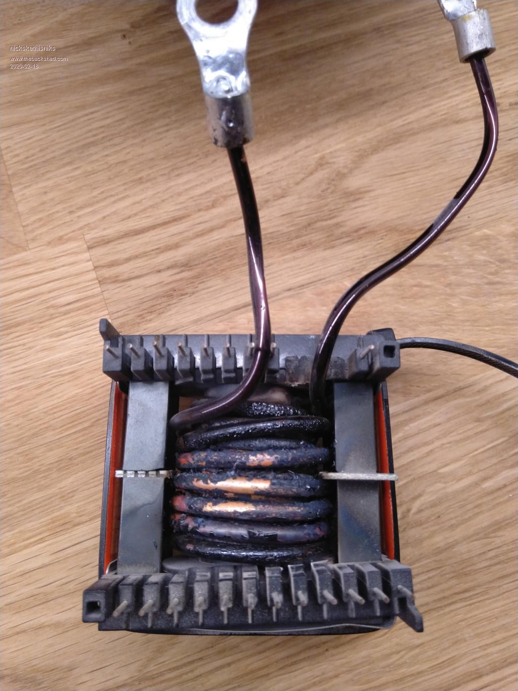 So had to speed up things and mount a more robust inductor. I just went for it and had the spare mosfets closeby ( fortunate not needed  ) )So I had to put in about 36mm airgap (2*18mm, it's more like an aircoil :) ) to get my 50ĄH, it's functioning about 2 weeks now. Fingers crossed it holds, sinewave does not change a lot under load. Now it's 30mm▓ instead of 10mm▓ should run a lot cooler with heavy loads. 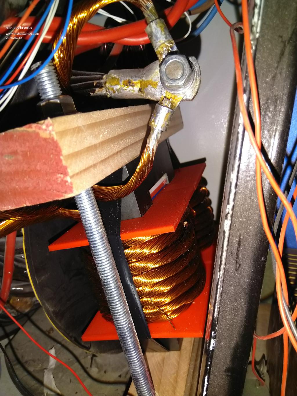 It will be temporary, It dropped to my mind the pla from the coilformer is only rated for about 50░C, that is to little. I must make a new coilformer with abs. The new coilformer will hold 6halves and will be suited for the whole powerrange this inverter can take. The airgap will be a lot smaller so should keep surprises away. This inductor will move to a spare inverter or other project. Sorry forgot to take a picture before mounting it in. Edited 2020-02-18 00:44 by nickskethisniks |
||||
| nickskethisniks Guru Joined: 17/10/2017 Location: BelgiumPosts: 409 |
So speaking of the new inductor, I let my wife draw the CAD files for my new coilformers.  Then I let a colleague print the formers in abs, this is the result: 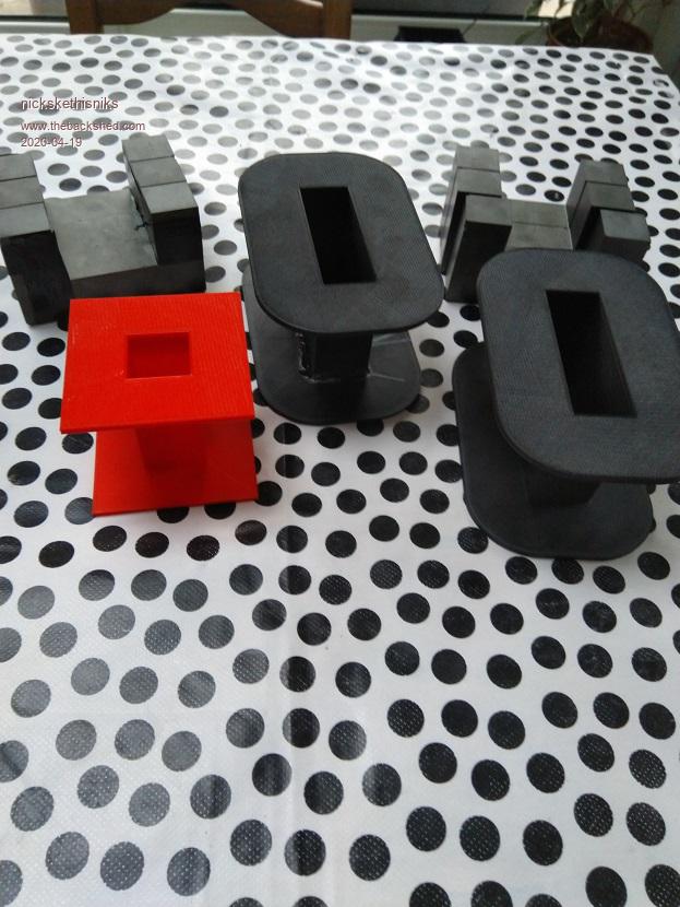 (So small mistake, Āthey are a little to big, but the grinder will help me with that.) 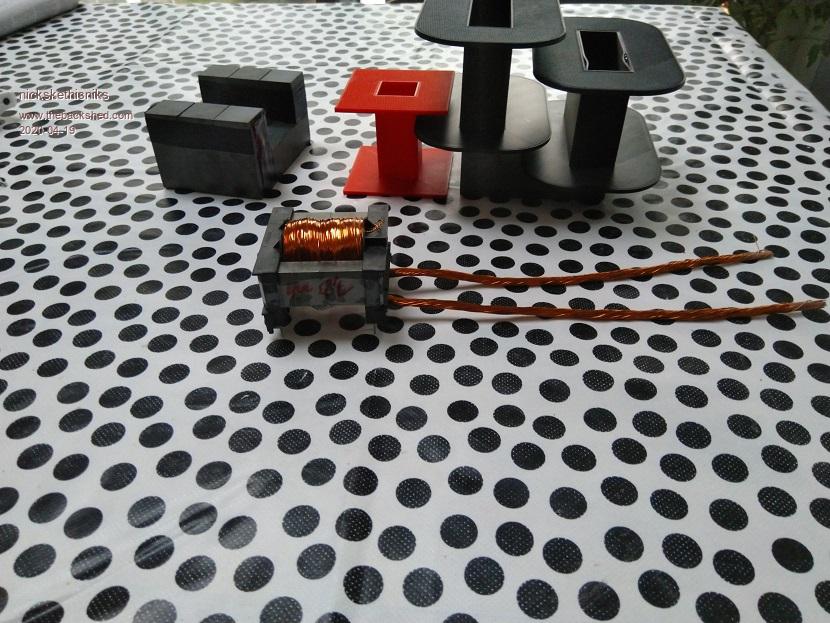 Edited 2020-04-19 20:41 by nickskethisniks |
||||
| Warpspeed Guru Joined: 09/08/2007 Location: AustraliaPosts: 4406 |
Very handy to have friends that can do things like that  Cheers, ĀTony. |
||||
| BenandAmber Guru Joined: 16/02/2019 Location: United StatesPosts: 961 |
Amber bought a bunch of dell laptops Text me if you would like one I thought you was new to back shed when You done that board for me Be nice to be able to return the favor and send you a lap top Most have i5 8-16 gig ram some have solid state hard drive some DVD burners some no cd rom All need reloaded or password cracked be warned i am good parrot but Dumber than a box of rocks |
||||
