
|
|
Forum Index : Microcontroller and PC projects : How to learn RF remote codes?
| Page 1 of 5 |
|||||
| Author | Message | ||||
Grogster Admin Group Joined: 31/12/2012 Location: New ZealandPosts: 9982 |
I have a need to use some little 433MHz transmitter units. Matching up a suitable receiver is no problem, but reading the data and learning the remote codes IS. I need to be able to learn new transmitter codes into the MicroMite in the next crazy idea I have. There are learning receivers all over eBay and AliExpress for only a few bucks, but they can only remember ONE code - I need to be able to learn up to 20 different ones. Here is a simple 2-page PDF for the RT1527 encoder chip: 2018-03-10_115403_RT1527.pdf Here is another datasheet for the same encoder, with a little more detail: 2018-03-10_115502_RT1527_HS1527_20-bit_remote-control_encoder.PDF Receiving the data from the transmitter is dead easy using something like an SYN470 Receiver Module Here is the datasheet for the SYN470R receiver chip. The 470 receiver is a lovely little chip, and is my go-to receiver device these days, and I have had much sucess with it, cos all the receiving and processing is done for you in this device. What I need to be able to do, is connect the data output line from the receiver chip to the MM, and read the data so as to learn the codes. That SOUNDS easy, but the problem is HOW. The data stream from the 470 device is not in any kind of pre-established protocol, it's just a stream of bits. Does anyone here have any bright ideas as to how I might go about reading the data stream into the MM? Once I have it in the MM, the rest is easy, but reading the data is going to be the tricky bit.  Smoke makes things work. When the smoke gets out, it stops! |
||||
crez Senior Member Joined: 24/10/2012 Location: AustraliaPosts: 153 |
after the sync bit is received, assuming an 80khz clock freq on the encoder for each data bit you would have to: wait for a rising edge wait 0.6 ms read the level and store it in a 24 bit buffer increment the buffer pointer all this happens in 1.6ms I think a cfunction would be required |
||||
| Grogster Admin Group Joined: 31/12/2012 Location: New ZealandPosts: 9982 |
Wow, yes, that is rather fast.  The 470 chip does have a useful pin - #12, WAKEB, which goes low when the device detects incoming RF signal, which could perhaps be used to trigger and release the Cfunction - if I end up doing it that way. Cfunction Gurus - what are your thoughts? Smoke makes things work. When the smoke gets out, it stops! |
||||
| Grogster Admin Group Joined: 31/12/2012 Location: New ZealandPosts: 9982 |
I hooked up a 470 receiver to my logic analyser and this is the output: 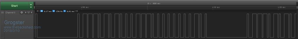 The sync seems to be about 6ms in length, followed by the data. This repeats like this: 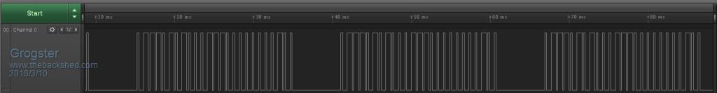 When no button is being pressed, the data is just white-noise. EDIT: Forum software is compressing these images, so they look a little fuzzy. Let me know if you want me to link to un-squeezed versions on Dripbox. (Dropbox) EDIT: Each of the bits in the packet appear to be 0.8ms each, regardless of if they are zeros or ones. Smoke makes things work. When the smoke gets out, it stops! |
||||
| WhiteWizzard Guru Joined: 05/04/2013 Location: United KingdomPosts: 2991 |
Hi G, This reminded me immediately of the Apple IR de-coding I done a few years back; and it looks like a similar technique can be used. Is the RXd data in the above image (according to the expected Tx stream datasheet) 24 bits as: 0111 0101 0001 1100 0000 0010 ? Also, please confirm the mS time between the start of each bit. In the meantime I will remind myself of my Apple decoding program written without a C-Function (but you may need to use a C-Function if the mS time is small) WW |
||||
| WhiteWizzard Guru Joined: 05/04/2013 Location: United KingdomPosts: 2991 |
If I understand you correctly, then you just want the MM to 'learn' (i.e. de-cipher) the 24bit values such as the one above I interpreted from your image? |
||||
| WhiteWizzard Guru Joined: 05/04/2013 Location: United KingdomPosts: 2991 |
Hi G, Check out this post - scroll down a bit and see an image 'identical' to your waveform  |
||||
| Trevorc Newbie Joined: 26/02/2017 Location: United KingdomPosts: 22 |
Hi, Some time ago, I needed the codes from a stair lift to be able to replace the remote. I came across this site, http://arduinobasics.blogspot.co.uk/search?q=RF+Remote+Capture You need to be a bit of a detective and able to use a spreadsheet, but it worked for me then. Good luck |
||||
| PeterB Guru Joined: 05/02/2015 Location: AustraliaPosts: 669 |
G;Day Grogster. That code was used many years ago in all sorts of places. One version was Hi for 80%, LO for 20% for a 1 and HI for 40$, LO for 60% for 0. I never understood why it was 80/20 & 40/60. When I used it I used 80/20 & 20/80 over a radio link with about 100 bits and repeated for error detection. To read the data you use a mono set to half the bit period and strobe. Good luck. Peter |
||||
| Grogster Admin Group Joined: 31/12/2012 Location: New ZealandPosts: 9982 |
@ WW - As per the 2nd datasheet which has a bit more information, they say that each word consists of a sync bit, 20 address bits, and 4 data bits, so 25-bit. 24-bit if you don't count the sync bit. Your interpretation of the data is how I see it, yes. Basically, looking at the datasheet, a short pulse-width is a zero, and a long pulse-width is a 1. Here are images of the first two bits following the sync bit: 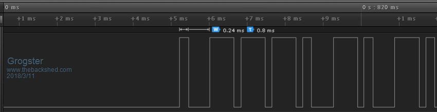 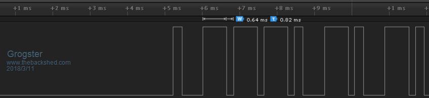 [Quote=WW]If I understand you correctly, then you just want the MM to 'learn' (i.e. de-cipher) the 24bit values such as the one above I interpreted from your image?[/Quote] Correct. Once I know what the 24-bit word is, the MM can save it permanently via VAR SAVE. I would probably do that via a single-dimension array of 20 elements. So I need to be able to 'Read' the code of a new remote into the MM and save it. The system will then respond to that remote as the MM has memorized it. At any point in time, a routine can be entered to re-learn remote codes, which will overwrite the old ones, allowing new ones to be programmed into that same 'Slot'. @ Trevorc - Thanks, I will read that link. Smoke makes things work. When the smoke gets out, it stops! |
||||
| Grogster Admin Group Joined: 31/12/2012 Location: New ZealandPosts: 9982 |
Yes, that appears to be what they are using for 1 and 0 in this data stream.  Can you please elaborate on your comment that "Use a mono set to half the bit period and strobe." - Confused. Smoke makes things work. When the smoke gets out, it stops! |
||||
| PeterB Guru Joined: 05/02/2015 Location: AustraliaPosts: 669 |
G'Day If the bit period is 0.8 ms, trigger a mono set to 0.4 ms with the rising edge of the data. Then fire a second mono on the trailing edge of that mono set to "skinny" to strobe the bits. The 1's will be HI and 0's will be LO. That was in the days before micros and you probably. Peter |
||||
| PeterB Guru Joined: 05/02/2015 Location: AustraliaPosts: 669 |
But wait there's more. I think you young blokes would set up an interrupt to fire on a rising edge and then read the data 0.4 ms later. But this is getting a bit clever for me. Peter |
||||
TassyJim Guru Joined: 07/08/2011 Location: AustraliaPosts: 6541 |
Grogster, Do you have control of the frequency setting resistor? If so, you can slow the pulses down a bit if needed. When I want to do small timing intervals, I make my own high precision timer. Set a PWM output to 100kHz and feed that output into one of the counting pins. Read the counting pin as required and you have 10 uS resolution. You still have the problem of program execution time but this UNTESTED test program is the way I would try first up. Assuming a 28 pin micromite, Connect pin 4 (PWM 1A output) to pin 15 counting input. Connect your signal to pin 16 I have taken 200uS as the short time and 600uS for the long time. The program does as little as possible: On a rising edge trigger, reset the counting variable. On a falling edge trigger, check the time since the last rising edge trigger and determine if it is a long or short pulse. Send a code then press any key to see the result. I have not bothered stripping sync pulses out or clearing the string at any stage. Jim VK7JH MMedit |
||||
| Grogster Admin Group Joined: 31/12/2012 Location: New ZealandPosts: 9982 |
Very clever!  Thanks. I will set that up and play with that concept later tonight. As the sync pulse is just a 'Long-low' to overcome the receiver white-noise, then the first pulse the MM should see, should be the rising-edge of bit-1, correct? Smoke makes things work. When the smoke gets out, it stops! |
||||
| TassyJim Guru Joined: 07/08/2011 Location: AustraliaPosts: 6541 |
I think the sync pules will be a short high followed by the long low. It won't matter. This is just to see if the mite can work fast enough. Jim VK7JH MMedit |
||||
| Grogster Admin Group Joined: 31/12/2012 Location: New ZealandPosts: 9982 |
code$ is all 1's, till the string is too long. No matter if I press the button or not. Does that mean the MM is not fast enough within the interpreter? Also, when NOT pressing a button, the receiver outputs white-noise, so I woluld love some pointers on how to deal with that. I am looking at another transmitter unit, which uses the MUCH easier to use SC/PT2260 transmitter and matching SC/PT2270 receiver chip. They are easier, as the decoder chip has a VT(Valid Transmission) output which the MM can use to know when there is a transmission coming in, and four data output pins that reflect what you code the transmitter for. The 1527 chip is a pain in the arse, actually......  Smoke makes things work. When the smoke gets out, it stops! |
||||
| TassyJim Guru Joined: 07/08/2011 Location: AustraliaPosts: 6541 |
You said earlier that your receiver had a squelch pin. Use that to enable interrupts when there is a signal and disable when no signal. The other device you are considering sounds easier to work with. Jim VK7JH MMedit |
||||
| PeterB Guru Joined: 05/02/2015 Location: AustraliaPosts: 669 |
Did you try my method? You would need to detect the long period of nothing to initialize the system but after that it should be easy. Peter |
||||
| Grogster Admin Group Joined: 31/12/2012 Location: New ZealandPosts: 9982 |
Yeah, Jim, I think you are right. There are other choices and the 2260 matched with a 2270 or 2272 is a beautiful thing, as the 2260 does the encoding, and the 2270/2272 does all the decoding for you, just driving output pins(on the decoder IC) which can directly interface to the MM. I have done this before in the past, and it worked a treat. The only REAL limitation, is that you can only have 15 transmitters, as you only have four data bits/pins on the decoder chip to play with. However, reading the four-bit data is DEAD easy with the PORT command..... Time for a rethink, perhaps. The 1527 unit is cheaper then the 2260 unit, but only by a couple of bucks. Smoke makes things work. When the smoke gets out, it stops! |
||||
| Page 1 of 5 |
|||||
| The Back Shed's forum code is written, and hosted, in Australia. | © JAQ Software 2026 |
