
|
|
Forum Index : Microcontroller and PC projects : Nixie clock PCB design for MM2
| Author | Message | ||||
| matherp Guru Joined: 11/12/2012 Location: United KingdomPosts: 11512 |
Prompted by redrok's thread I've designed a PCB for a MM2 based Nixie clock. The requirements I designed to were as follows: Low cost Nixie tubes Easy to solder 12V supply GPS or DS3231 as clock source IR or push button control Minimum off-PCB connections The layout I've come up with is as follows: 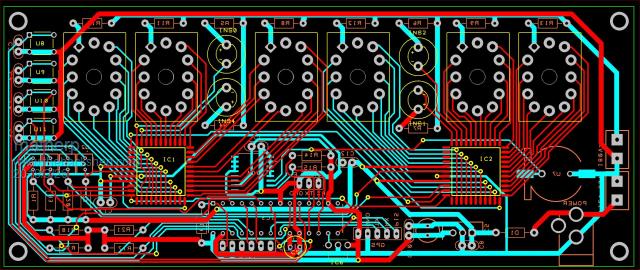 All components are through hole except for the HV5530PJ-G which are 1.27mm pin pitch (easy to solder) and the DS3231 if fitted. Power supply is 12V feeding a cheap high voltage converter like this. The Nixie tube set is also cheap. This is the set I have ordered These can be soldered direct to the PCB or connected using standoff sockets The PCB is 167mm * 69mm � cost USD55 for 10 including HK post shipping (PCBGogo) The circuit is: 2018-03-26_202109_Nixie_-_Project.pdf The key component is Microchip's high voltage 32-bit serial to parallel converter HV5530PJ-G This is an SMD part but is on a 1.27mm pin pitch (easy). This runs on 12V logic and coupled with the MOSFET level changers completely isolates the MM2 from the high voltage supplies to the Nixie tubes and allows three tubes to be driven by a single chip. The 4-dots comprising the "colons" can be individually driven allowing alarm setting and status to be indicated by your software. I'm currently waiting on parts to prototype the key bits of the circuit. Assuming this is OK I'll get some PCBs made. If you are interested in a PCB, WW has agreed to stock them but please note: WARNING HIGH VOLTAGES This project uses high voltage (180VDC) to drive the Nixie tubes. If you want to build this or other high voltage projects you should ensure you are fully familiar with the safety requirements of working with high voltages. The 12V supply to this project must be fully isolated from the mains. I believe the track to track clearances on the PCB are adequate for the 180V low current supply, certainly they are greater than the pin spacings on the driver chip but any builds based on this design are at your own risk |
||||
redrok Senior Member Joined: 15/09/2014 Location: United StatesPosts: 209 |
Hi Matherp; Very Nice!!!!! I see there are Console and ICSP connection, very handy. I might suggest breaking out at least 1 of the unused pins for use with a precision 1 pulse per second input. Although, I see, one could use the ICSP connector for this. I suggest this because I have been using a cheap U-BLOX GPS receiver which supplies a 1PPS timing pulse. I have been using the internal uMITE RTC, Real Time Clock, for time counting. Of course this is not very accurate. By watching the 1PPS and switching between 2 "Option Clocktrim" values the internal clock is disciplined to very high precision. ( Btw, I assume this is "Legal" as I've been doing this once per second for about a week. Clearly this operation hasn't "Worn Out" anything yet. Am I correct about Clocktrim not wearing out?) A kind of "Poor Mans" phase locked loop synced to the GPS timing pulse. Works very nicely. Technically there is up to +- 10mS timing jitter due to my software but plenty good enough for a clock. redrok |
||||
| matherp Guru Joined: 11/12/2012 Location: United KingdomPosts: 11512 |
There is one on the GPS connector which matches the pinout of the GPS module I'm using. Yes, it just writes to a memory register so can be used as often as wanted with no impact |
||||
| redrok Senior Member Joined: 15/09/2014 Location: United StatesPosts: 209 |
Hi Matherp; I guess I hadn't seen the GPS connector. I have that same GPS, works very reliably. I have a little 555 timer "Missing Pulse Detector" watching the 1PPS pulse from the GPS. Its been running for over a year without missing a single pulse. (Except, of course, when I'm messing about with it. :^) ) How do I get the PCBoard? Put me on the list for 2 please. Thanks!!! redrok |
||||
| bigfix Senior Member Joined: 20/02/2014 Location: AustriaPosts: 130 |
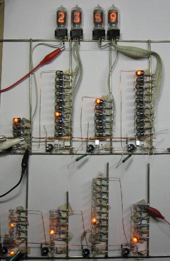 For the hardcore "neon" technology fans - but not stable in the end... All Nixie/Bulb Clock cheers Guenter |
||||
| matherp Guru Joined: 11/12/2012 Location: United KingdomPosts: 11512 |
The Nixie tubes arrived yesterday and...... The footprint was upside down on my layout and I want them at the top of the PCB so had to do some serious rework.  However, other than that the circuit seems to work nicely when prototyped. However, other than that the circuit seems to work nicely when prototyped.I've also put a footprint for a TEMT6000 light sensor on the front of the PCB so the clock can be auto-dimming. 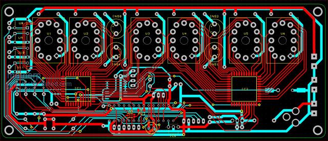 2018-04-13_013313_Nixie_-_Project.pdf |
||||
| redrok Senior Member Joined: 15/09/2014 Location: United StatesPosts: 209 |
Hi Matherp; I wish I had caught that as I did look over the layout when you first posted it. I have a text file I have been using in my Nixie Clock design. This has been very useful so I don't get things confused. ------------------------------------ redrok IN-12B IN-12B Number sequence Front to Back 3 8 9 4 0 5 7 2 6 1 ()=Pin# Top View Top Of Number 6 (6) 6 5 (7) ^ (5) 7 4 (8) /|\ (4) 8 3 (9) IN-12B (3) 9 2 (10) | (2) 0 1 (11) | ->(1)Anode d.p. (12) ()=Pin# Bottom View Top Of Number 6 (6) 6 7 (5) ^ (7) 5 8 (4) /|\ (8) 4 9 (3) IN-12B (9) 3 0 (2) | (10) 2 Anode(1)<- | (11) 1 (12)d.p. ()=Pin# Bottom View d.p.(12) 1 (11) | ->(1)Anode 2 (10) | (2) 0 3 (9) IN-12B (3) 9 4 (8) \|/ (4) 8 5 (7) v (5) 7 6 (6) 6 Top Of Number ------------------------------------ IN-2 IN-2 Number sequence Front to Back 3 8 4 7 9 5 2 0 6 1 ()=Pin# Top View Top Of Number 7 (7) 7 8 (6) ^ (6) 6 9 (5) /|\ (5) 5 0 (4) | (4) 4 Anode (11) IN-2 (3) 3 Bump | (2) 2 (1) 1 ()=Pin# Bottom View Top Of Number 7 (7) 7 6 (6) ^ (8) 8 5 (5) /|\ (9) 9 4 (4) | (10) 0 3 (3) IN-2 (11) Anode 2 (2) | Bump 1 (1) ()=Pin# Bottom View (1) 1 Bump | (2) 2 Anode(11) IN-2 (3) 3 0 (10) | (4) 4 9 (9) \|/ (5) 5 8 (8) v (6) 6 7 (7) 7 Top Of Number ------------------------------------ |
||||
| RyanHammond Newbie Joined: 29/03/2018 Location: United StatesPosts: 15 |
Hello, this is a pretty cool project. I am hoping you are willing to share the time clock code. I am working on something similar, not using nixie tubes, but using shift registers to drive regular common anode 7 segment leds for a clock. Your ideas would be of great help. Learning lots on this forum and the micromite is a great tool. I am somewhat amazed that this isn't as widely known as it deserves to be. Thank you for your help. |
||||
TassyJim Guru Joined: 07/08/2011 Location: AustraliaPosts: 6538 |
Saw this in an "antique" shop today. 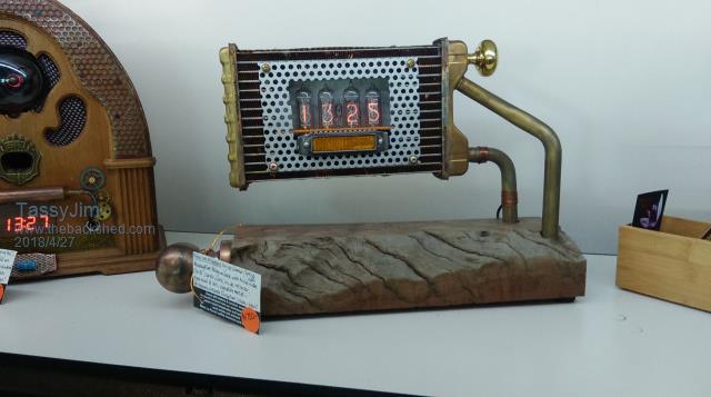 It's still on the shelf it you are interested. The price is over the top - $1750.00 Beside it is a fake (or butchered) radio with an old digital clock planted in the center. Jim VK7JH MMedit |
||||
| RyanHammond Newbie Joined: 29/03/2018 Location: United StatesPosts: 15 |
Has there been any progress on your project matherp? Dying to see the end game here. This is beyond cool!!! |
||||
| CaptainBoing Guru Joined: 07/09/2016 Location: United KingdomPosts: 2171 |
just seen this... https://www.youtube.com/watch?v=ge_9CNiZZ_A |
||||
| The Back Shed's forum code is written, and hosted, in Australia. | © JAQ Software 2026 |
