
|
|
Forum Index : Microcontroller and PC projects : Micromite to Micromite using serial
| Author | Message | ||||
| RyanHammond Newbie Joined: 29/03/2018 Location: United StatesPosts: 15 |
I have something in mind that I think would work great using the Micromite system. I want to have 1 micromite designated as a "master" and a few "slaves" and I want the slaves to just listen for them to be addressed and do something the master says to do. I would like to use the serial port, maybe at no more than 9600 to 19200 baud because I have to have relatively long cable runs to each slave from the master. So basically the slaves would only sit there and wait for their address to be sent, and if recognized, the next data sent would be and instruction, and then maybe one or two bytes of "data". The slaves would not ever respond to the master, so there would only be one way communication. So what I was thinking is to be able to use regular Ethernet cable to connect everything together and because of the long cable runs and also employ using something like the 75176 differential line driver transmitter on the master and all the slaves would use the receiver side of the chip. I would only have to use 2 of the lines for the communications and one for common ground. So that leaves me with 5 lines left over. So I was thinking that I could use 2 for power and 2 for power ground. If I send 12v over the Ethernet, I could use a 3.3v voltage regulator to power the slave micromites. So the master would basically send an address byte, then a command byte, and possibly one or max two data bytes. The slaves would all just "listen" to the master and if the slaves address was relevant, then it would wait for the next 2 to 3 bytes to know what to do. So, my question finally is... Can the slaves just sit in a loop of some kind and wait to "hear" their address. If they hear their address, they know that the next byte would be their instruction, and the next byte or two would be the data for that instruction. Is the BASIC fast enough to react to that type of serial data? Again, there would be no response from the slaves back to the master micromite, just one way communication. All the "processes" that the slaves would do would be done relatively quickly and independently and they can just do their thing and go back to "listening" for the next instruction if they hear their address. I just want to be able to create basically a one way network I guess. Is this even the right way to go about that? I want to keep it very simple, yet, effective. I was hoping that at a slow speed, the serial information would keep its integrity. Or maybe the master would have to transmit the information twice just so the slave would know that the data was proper. (not sure here). As an example, the master would send and address like "A1" and then an instruction like "I5" and then data like "10". The A1 would mean micromite at address 1. The instruction I5 would be something like "count up" and the data "10" would be 10, ie, count up to 10. The master doesn't care if it happened or when the slave was done. It just sends the instruction and data info and goes about its day and the slave does what its told and then goes back and listens for more instructions if it hears its address again. Sorry for the long post. I think this process may work, but without completely building it just to test, I want to make sure that this is even a feasible thought or if there is a better way to go about this before acquiring parts and trying to figure out the program. Has anyone tried to do this type of "networking" with micromite and if so, am I thinking about this the right way? Has something already been developed for this simple type of networking? Thank you for any help. |
||||
TassyJim Guru Joined: 07/08/2011 Location: AustraliaPosts: 6538 |
I do something very similar. You need to decide what system you are going to use for the 'multidrop' serial line. The TX from the master goes to all slave RX pins OK. The TX from the slaves has to be multiplexed. I use diodes on each slave TX to the common wire and a resistor on the master. Cheap and nasty. I also use MAX232s to isolate the micromite a bit and give me 5V to play with instead of 3.3 for the data lines. I use the console ports which lets me use INKEY and do software updates over the same line. The COM1 or COM2 could be used just as easily with interrupts for data received instead of INKEY. A typical command sent would be $9LL24 where $9 is the slave address LL is the command to "List Last" and 24 is the number of records to list I also reserved $0 for the global address which could be used to update all slave clocks at once. This is a cut down example of one slave Once the main loop detects a character arriving, it calls the doKey sub which waits for an end of line (or overflow) It then calls the doCmd sub which checks if the command is for it, what the command is, and any other data associated. It then PRINTs the reply. To allow for software updates, you need to disable ^C and there is a command to put the slave to sleep for a while so it doesn't see the software intended to a different slave. This is not a feature I have tried in earnest. It is simpler (and safer) to use the COM ports for data interchange and a laptop to do software updates. Jim VK7JH MMedit |
||||
goc30 Guru Joined: 12/04/2017 Location: FrancePosts: 435 |
hi Ryan Your problem is classic. it can be solved with the MODBUS protocol. This protocol works in master-slave mode, with the first byte defining the address of the slave (and 0 if message for all the slaves - without answers), then a function code and as the case 1 or more bytes, with at the end of the frame, a crc that makes sure the right message. The master questions, the slave answers. The following exchange is initiated by a time out In your case of local use you can define your own function codes on 1 byte, but the simplest is to stay at the standard see here : http://modbus.org/docs/PI_MBUS_300.pdf this systeme work in half-duplex. you can use a modem on 2 wires but you can also use in tcp/udp mode with network connexions |
||||
| MicroBlocks Guru Joined: 12/05/2012 Location: ThailandPosts: 2209 |
Micromite manual page 84 is about IEEE 485 which does exactly what you want. Microblocks. Build with logic. |
||||
| Turbo46 Guru Joined: 24/12/2017 Location: AustraliaPosts: 1693 |
Hi Ryan, As goc30 says the MODBUS protocol is absolutely suitable for your application as also is RS485 (IEEE 485) but there is no reason that you can't make up your own protocol as you describe. Depending on how critical your application is you should consider a CRC at the end of your message to ensure that it is not corrupted. Also consider two-way (full duplex) communications where the slave answers with an acknowledge (ACK) code (with slave address and CRC) to confirm that it has performed the command and also that the slave is still alive! The RS485 signal can be 'daisy-chained' from one slave to the next with the last one having a terminating resistor - it can be used on quite long runs (100s of metres). If each of your slaves will have a separate run and are not daisy-chained then you should use a separate 75176 (or similar) (MAX485?) for communication with each slave. See Here for a discussion on the MODBUS CRC - you don't have to use the MODBUS protocol to use the CRC - it can just as easily use with your proposed protocol. Bill Keep safe. Live long and prosper. |
||||
| CaptainBoing Guru Joined: 07/09/2016 Location: United KingdomPosts: 2171 |
the problem with using serial as a bus is the conflict of signals. This can be solved with a mixture of open collector/drain outputs and pull-ups. Using a radio link provides an open medium that can support many devices without any hassle caused by conflicts. I developed an addressed serial network using HC-12 433MHz links, but any would do. fruitoftheshed.com/MMBasic.Short-range-radio-network-not-WiFi-SLAVE-module-Uses-cheapie-433MHz-modules-or-HC-12.ashx this has a master + upto 998 (as written) slaves with discovery and multiple message types/formats - the radio traffic is encrypted. It's not a heavy duty encryption but stops basic snooping. I had RC4 but the smaller micromites could struggle to keep up in the 1.5 second window response times. |
||||
| RyanHammond Newbie Joined: 29/03/2018 Location: United StatesPosts: 15 |
Tassy Jim, I like that example. I would probably wind up using the com port instead of the console. Your example gives me great insight. I was also looking at the GPS clock example code on Geoff Grahams website. The way he polls the gps units serial stream looking for certain characters, at first seemed like a good way also, but your example shows how waiting for an address works. Thanks for that! Also thanks for all the other responses, but I really am just trying to keep it simple one way communication at this point. The CRC is just way over my head at this point. I noticed in the manual the pulse command and pwm, etc. are handled in the background and once instigated, your program just continues to run. Is this the case with serial communications also, as there are buffers? For example, if I tell the micromite to send out a string of characters on the tx pin, will the next line of code not execute until the entire string is sent out, or will the string send out in the background and the next line of code executes immediately? One more question for those that have used rs485 (or rs422). I see differing opinions on the web as to having a common ground connection between the master and slave devices. Even on amazon, I see usb to rs485 converter modules that have just 2 terminals for the differential twisted pair connection between two units, and some have 3 - 1 extra for a ground. In this particular application, I might have up to 100 foot cable runs between two units, each having its own power supply. My data rate will be relatively slow, maybe I will try to go as high at 100k-ish baud if possible. Is the common ground connection necessary with rs485 or rs422? Thanks again, this is a very helpful forum. |
||||
| CaptainBoing Guru Joined: 07/09/2016 Location: United KingdomPosts: 2171 |
hmmm... busted link. Dunno what happened there. http://fruitoftheshed.com/MMBasic.Short-range-radio-network-not-WiFi-SLAVE-module-Uses-cheapie-433MHz-modules-or-HC-12.a shx?HL=radio |
||||
| RyanHammond Newbie Joined: 29/03/2018 Location: United StatesPosts: 15 |
After a bit more thought, being able to have 2 way communication might be desirable. I did a bit of reading thanks to MicroBlocks suggestion and in the manual it reads... "The 'DE' option in the OPEN comspec$ for COM1: specifies that the Data output Enable (ENABLE) signal for the IEEE 485 protocol will be generated. This signal will appear on pin 7 on the 28-pin chip and is normally high. Just before a byte is transmitted this output will go low and when the byte has finished transmission the output will go high again. Note that this polarity is the opposite of that used in the Maximite family and an inverter is normally required to drive the DE input of an IEEE 485 transceiver." Does the last sentence mean that an inverter is normally required for the Maximite or is it required for the Micromite? If worse comes to worse, instead of trying to use just one pair in the ethernet cable for RX and TX, I could use 2 pairs, one for the Master TX to all the slave RX and the other pair for all the Slave TX to the Master RX. I am assuming that the Master TX to Slave RX can all be daisy chained together, but I would have to use the DE on pin 7 when a Slave is going to talk back to the Master, which from the description sounds like the micromite handles this automatically. The slave would only talk to the master if the master actually asks the slave for a response. Is my logic correct here? Since the slaves would only really say, "OK, got it" back to the master, is it a waste to use the extra twisted pair just for that, would it make more sense to use the DE line on both the master and slave to "share" the one twisted pair? I know I am asking a lot of questions, I just want to figure out my approach before breadboarding anything and start off on the right foot. I appreciate all replies very much. |
||||
| Turbo46 Guru Joined: 24/12/2017 Location: AustraliaPosts: 1693 |
I have experience of using RS485 in electricity substations. These are fairly noisy environments especially during high voltage switching and fault conditions. Earthing the RS485 signal was never done. The RS485 signal is best sent over a single twisted pair shielded cable, the shield of which is earthed ONLY at one end, usually at the master end. Each end of the cable is terminated with a 120ohm resistor (from memory). Communications between devices is implemented using MODBUS or more sophisticated protocols incorporating event timestamping. CRCs greatly reduce the risk of message corruption causing errors. An acknowledge (or back indication) message confirms that the command has been received and acted upon or if an error has occurred. There is no risk of signal conflicts because the slave only responds when it is spoken to. You could consider transmitting the command twice as you suggest and make the slave check that the two messages are the same before acting on it, that may be secure enough for your application. BUT, without an acknowledgement message how will you know? One of the messages may have been corrupted and the command was not carried out. RS485 is made for two way communication; no additional hardware is required except maybe an inverter to drive the DE/RE lines. Consider using one byte in the message to tell the slave how many bytes the message contains or perhaps use a fixed message length to simplify the message handling. Sorry, this was written before I saw your last post. Yes, use only one pair for the RS485 and I believe the inverter is required for both the Maximite and the Micromite. It could be a simple transistor inverter rather than using an IC. Bill PS Using a separate pair for master transmit and receive would mean using an additional transceiver chip at each end. Keep safe. Live long and prosper. |
||||
| Phil23 Guru Joined: 27/03/2016 Location: AustraliaPosts: 1667 |
I'd Second Wireless with 433Mhz. Using HC-11's here. The Master requests data from 4 slaves. Wiring those 4 units together would be a nightmare. Add to that I have two E100's that collect the responses the masters collect & display the data. One up in my office & the other floats about the house & yard with a battery pack. A 4th slave will be added in the next week or so. That MM will simply live at it's location only needing connection to the device it reads. Phil. |
||||
| TassyJim Guru Joined: 07/08/2011 Location: AustraliaPosts: 6538 |
With the length of the cable run, even I would consider Wireless (and I much prefer wired). If you do stick with wired, IEEE 485 is definitely the preferred physical link. I am a bit concerned with your wish for "100k-ish baud". That will get interesting. Jim VK7JH MMedit |
||||
| RyanHammond Newbie Joined: 29/03/2018 Location: United StatesPosts: 15 |
The 100k is a hope and a prayer, but for what I'm actually doing, 9600 to 19200 will be more than sufficient. During the testing phase, I will try to see what the actual limitation is just for fun over a very long cable run and try to gather some results. At this point the wireless is pretty much out of my league, but this particular project is a wired permanent setup so no choice there. The thought of using wireless is however very interesting and I will want to pursue that in the future. How have people implemented inverting the pin 7 DE signal to control the rs485 chip? Would a simple transistor do, or do I need to use an logic inverter IC? Not sure if speed is an issue. Instead of using pin 7, can I just use any pin to "manually" control the DE pin and not have to worry about inverting pin 7? Parts are coming in tomorrow and I will start the testing. I opted for the 3.3v version of the 75176 which is the MAX3485 so I can get away with just one voltage regulator. Thanks for all the great help! |
||||
| Turbo46 Guru Joined: 24/12/2017 Location: AustraliaPosts: 1693 |
Hi Ryan, have a look Here for a post on the DE signal. A transistor inverter is shown but no component values are given. I would suggest a 100k base resistor, a 10k collector resistor and any small signal transistor you have to hand. The resistor values are not critical at all just make the base resistor (say) up to 20 times the value of the collector resistor and choose a collector resistor that will not draw too much current from the power supply. Bill Keep safe. Live long and prosper. |
||||
| RyanHammond Newbie Joined: 29/03/2018 Location: United StatesPosts: 15 |
That is an interesting thread, thanks Turbo46. In a last ditch effort to not have to add parts... Is it possible that since you can read the state of an output pin, would it be feasible to use something like... setpin XX, Dout and then right before you send the print to the com port do... pin(XX) = Not pin(7) and use pin XX to control the DE input of the RS-485 driver chip? Or can there be a function of some kind that simply reads pin A and inverts pin B as an option. It would just follow one pin and inverts another pin? I know it would mean one less pin to be able to use, but it would eliminate having to add extra circuitry. Since the serialTX added function can transmit serial data on any pin, could it have an option that would use another pin the toggles the DE with the correct polarity maybe? I guess you would have to use the serialRX function with the same DE pin if you were doing 2 way communication if this is possible. Again, just a last ditch effort... I just noticed reading the serialRX function PDF it says... Parameters The SerialTx function (created by adding the above code) takes four to six parameters: r = SerialTx( pin, baud-rate, string$, timeout, maxchars, termchars) I think the SerialTX should read SerialRX. I just re-read the SerialTX and SerialRX added functions docs again and it says... The function will not return until all of the characters in the string have been sent. Does this make it feasible to simply set an output pin to control DE one line before issuing these commands and then inverting that pin in the next line of code? |
||||
| Phil23 Guru Joined: 27/03/2016 Location: AustraliaPosts: 1667 |
From that post, I've gone with the 2nd module pictured & it's working just fine. It does the directional switching it's self. Phil. |
||||
| Turbo46 Guru Joined: 24/12/2017 Location: AustraliaPosts: 1693 |
Hi Ryan, I doubt that your first suggestion would work, Geoffg or matherp would know but if I am reading your second suggestion correctly I think that WOULD work i.e. - Choose your own DE pin and set it as Dout. Set DE high Transmit your data... Set DE low I would leave Comspec$ as the default and go with that. In that case DE is not defined by the OPEN command and baudrate is 9600. I have not done any of this with the MM so I would have to defer to those with more knowledge and experience. I'd love to know how you go. Bill Keep safe. Live long and prosper. |
||||
| CaptainBoing Guru Joined: 07/09/2016 Location: United KingdomPosts: 2171 |
Please don't be put-off. HC-12s contain a processor that does all the tedious mucking about. This really is so easy you'll wonder why you never played before. All you do is have two radio modules... HC-11 or HC-12, say. You take the TX/RX at one end into the correct pins on the module and do the same at the other end. Whatever goes in at either end pops out at the other - it really is that simple. The only gotchas are getting the tx/rx pins the right way round (they are relevant to the whatever you are looking at right at the moment, so the Tx on the micromite is an output so it goes to the Rx pin on the radio module) and getting the baud rate for the distance. I can't speak for HC-11 but HC-12s have a mode on them that will do a mile in open field tests(!) but not at 115K... they will do it at 9600 though and if the area is noisy or lots of walls, just drop the speed. Another might be the channel but they should all come factory fitted to channel 0 (upto ch127 I think) If you projects that want to use wireless but not with each other, you can easily switch the relevant pairs onto another channel. Here is a picture of my wireless link that I knocked together in an hour for access to awkward placed devices. The bit on the left goes into a PC or phone, the bit on the right plugs into any number of micromite devices I have. It is four components and some wires. Told you it was easy. The radio links just remove the need for wires. Now, shoo!, off to ebay with you!  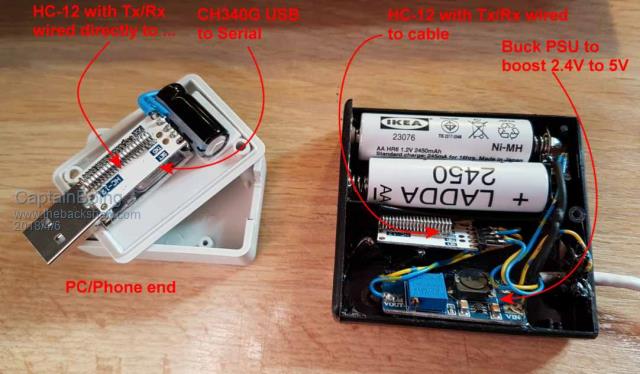 I use this for making my life easier when servicing units in awkward places - for instance, I have about 100 units for Snooker-hall light control (not all at the same place). They are all hidden in the false ceilings so instead of me wobbling about on top of some steps with my laptop, I plug this in and work in comfort with my feet on the ground. When I am done, I unplug and move on to the next. I can even plug the PC end into my phone with a bus master adapter and talk to them from my S7 - great for just snagging some logs etc... |
||||
| RyanHammond Newbie Joined: 29/03/2018 Location: United StatesPosts: 15 |
Thanks everyone for the ideas. I have implemented TassyJims's code, but using the serial port instead of inkey, and I have to say, this works wonderfully!!! I am just checking on the receiving micromite for a start character and then read the rest of the very small string that follows, and execute different commands. I haven't yet tried a long distance cable with differential drivers, just simple breadboard to breadboard using jumper wires at about 2 feet in length, one signal and one ground. I have run tests for days and things are working great. Now to test two way communication using a differential line driver, but the thought of having to invert the DE signal is still a thing. Not a big thing, just a thing. Adding two resistors and a transistor to invert that damn signal. Oh well, there are starving children in this world, so my problem amounts to nothing. After searching for a bit, I figured I could make a cool 10 million and retire, if I could just make the chip with selectable logic on that pin. But the demand for that may be a bit lower than my retirement goals. I am cruising along at 9600 baud, which is plenty fast for what I'm doing, but tried up to 115k. That worked, but errors once in a long while. So very confident that 9.6 to 19.2k will work VERY well for whats happening here. Thanks again for all the help and inspiration. Micromite is awesome! P.S. looked into the wireless option. That is pretty cool so I ordered some of the HC boards. But here in the states, I have a feeling that if I want to sell something like this, the FCC would be on my butt pretty quick. But I will def. try and play with those for some home based stuff. |
||||
| The Back Shed's forum code is written, and hosted, in Australia. | © JAQ Software 2026 |
