
|
|
Forum Index : Microcontroller and PC projects : AC measurement
| Author | Message | ||||
| Alastair Senior Member Joined: 03/04/2017 Location: AustraliaPosts: 161 |
I want to measure some 240vAC mains current & voltages and display them on a MM driven display. I do not want a direct connection to the mains for the wiring that will wend its way to the MM. For the current I will use something like current loop For the voltage I am stumped other than using a voltage divider linked to say an E-28 and then send the result to the main MM by serial with the above current connection. There must be a better way. Cheers, Alastair |
||||
TassyJim Guru Joined: 07/08/2011 Location: AustraliaPosts: 6538 |
The safe way to measure mains voltage is with a low wattage transformer. Any old plugpack that outputs AC will do. When I made a disturbance recorder, I used voltage dividers on the ~7V to bring the peak down to +-1.5V and then used a voltage reference of 3.3/2 for one leg and measured the other leg to give a waveform going from zero to 3.3V This is a link to the discussion https://www.thebackshed.com/forum/forum_posts.asp?TID=7158&KW=disturbance+recorder The same idea for the output of a Current Transformer would also work. Jim VK7JH MMedit |
||||
| Turbo46 Guru Joined: 24/12/2017 Location: AustraliaPosts: 1693 |
Have you seen the Silicon Chip project "Touchscreen appliance energy meter" in the August/September 2016 issues? If not it may be worth a read. Bill Keep safe. Live long and prosper. |
||||
| Alastair Senior Member Joined: 03/04/2017 Location: AustraliaPosts: 161 |
TJ, Yes you are right that a step down transformer is the best way to get the isolation. I should have included that I was looking for a compact solution as I would like about 6 sensing units and want to have minimum alteration to the existing systems. I have been searching for ICs/modules but so far nothing suitable. I thought that there would be an IC that would connect to the AC and produce an isolated output via say I2C with the various parameters like peak, av, freq, etc. So far my search has failed. I will spend a bit more time and then perhaps modify the aim and use a small transformer. Bill Vaguely remember it - will look it out and have a look Cheers, Alastair |
||||
| Alastair Senior Member Joined: 03/04/2017 Location: AustraliaPosts: 161 |
I have done further searching and now found lots of ICs that do power control/monitoring/control/analysis but they all seem to need the voltage step down/isolation to be done externally. I many cases the examples show resistive dividers which I want to avoid to have a higher level of safety. I have spent enough time searching. Will now go look at the SC article mentioned above. The SC unit uses a step down transformer and a hall effect current sensor. It also uses an external A to D which I will look into. My experience with the MM internal ADC has been the one disappointment with the MM. All of the variants I have tried tend to have very noisy results even though I have spent a lot of time with analog ground separation and filtering. In one project I gave up after having tried 3 different MMs and used a simple 12 bit ADC which immediately gave quiet results. Thanks for the input. I will now look for a nice small transformer and check my parts for ADCs. Cheers, Alastair |
||||
| Solar Mike Guru Joined: 08/02/2015 Location: New ZealandPosts: 1213 |
Have a look at this article, it describes a circuit that uses two opto-couplers in a bridge arrangement, one is driven by the high voltage you want to measure, the other is part of an op-amp feedback circuit that maintains a balance in the currents flowing and thus the ratio of voltages. Thus no transformer required. 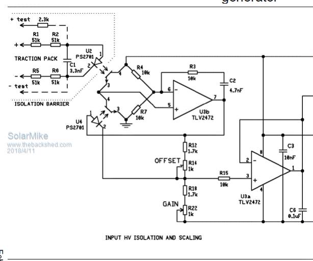 I was going to use something like this to measure 300V DC battery sets powering high voltage inverters. For AC just rectify the supply. Article Here Page 6 Cheers Mike |
||||
| The Back Shed's forum code is written, and hosted, in Australia. | © JAQ Software 2026 |
