
|
|
Forum Index : PCB Manufacturing : Library completely empty a bit confusing
| Author | Message | ||||
bigmik Guru Joined: 20/06/2011 Location: AustraliaPosts: 2870 |
G�day Plover, You need to assign track thicknesses and via sizes as your tracks and vias look way too thin. I use 0.01� for most tracks with 0.01� spacing and I like vias that are 0.03� dia with 0.015� dia hole. Smaller are called micro vias and you will find that either the manufacturer can�t handle them or cost will rise considerably. Mick Mick's uMite Stuff can be found >>> HERE (Kindly hosted by Dontronics) <<< |
||||
plover Guru Joined: 18/04/2013 Location: AustraliaPosts: 302 |
Hi Mick, Ah, thanks for mentioning the track width, yes of course now I can see they are nowhwere near what I used to make, actually I can't even remember the figures. Tonight I was planning on getting the correct comp values put in and probably move the Schematics around. I have spent some time collecting a number of your parts from a TBS topics and also from the Dontronics lair but not had time to look in the zip files. How you got any pointers on hw you catogorize your components, such in one big library file, number of files etc I guess there is no standard way. In Protel was there not an action whereby you could have the program generate a complete copy of all the parts used in a project? My scanning of the DEX manual has not made me stumble over such yet? Last night I removed the massive Library called 'Cat1' when downloaded from the DEX web site but it really slowed my machine down, though the searching would bring many components when looking. I almost think it would be quicker jut looking a component up on the internet and build from that, but it is a bit of re-inventing the wheel. What I have missed finding out so far is if a symbol, say a transistor can have several foot prints associated, for example through hole and surface mount? One symbol many feet plates?? |
||||
| plover Guru Joined: 18/04/2013 Location: AustraliaPosts: 302 |
Hi Mick, I am now rather much in trouble. I very carefully followed your demo exercise when looking at getting board routed. From what i can see Electra now comes installed?? Here is the manual I have set up the directory as shown in the first quote but nothing happens when I start building the board ie the end product is just the nets, no tracks. I guess since a number of updates taken place since your tutorial that the router start icon has move because I find the start here 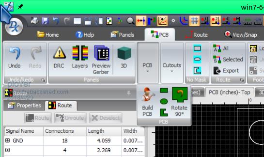 |
||||
| bigmik Guru Joined: 20/06/2011 Location: AustraliaPosts: 2870 |
Hi Plover, It has been a while as I said since the manual was written, If you installed DEX I believe Electra will get installed as a matter of course you may need to register with ELECTRA for the free license.. Mine does it automatically so I havent needed to do anything to get electra going.. If you still cant get electra to route I would pose a question on the DEX forum: DEX FORUM Start a thread with your setup and that you cant get Electra to do anything. Kind Regards, Mick Mick's uMite Stuff can be found >>> HERE (Kindly hosted by Dontronics) <<< |
||||
| plover Guru Joined: 18/04/2013 Location: AustraliaPosts: 302 |
Hi Mick, Thanks, well each time you post I get 'a good idea'. Went to the link site, but is it not defunct? Tried to register but just told 'no invitation'. Guess the feedback channel next but here is what dawned upon me. 1.. Went to Electra directory and clickeded on the start file Got failure message, looked in the event viewer, the result I thought perhaps it is out of date. 2.. Followed your link to ELECTRA and downloaded a file. Going to the Electra site does not give you that option, think because I have not registered. The downloaded file installed, 'somewhere' I traced down the directory and went into DEX and placed this directory in the Electra setup field. 3.. Clicked around a bit 'haphazardly' well guessing that an icon might set Electra Off and it certainly did. Openec up a page full of information, that meant nil to me at the time. I wondered where I should hit the start button, still haven't found it. Looking around found my circuit had been routed faster than I could let go of the mouse click. I was expecting a couple of minutes but then again only 82 nodes ? Not got time look any further now, will have to wait till later tonight. Ahh yes my grace period on this is only 14 days? Again I am guessing because I have not signed up. 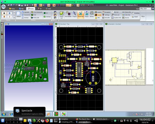 This time I noticed the track width are very narrow, looking into this as well. |
||||
| plover Guru Joined: 18/04/2013 Location: AustraliaPosts: 302 |
Have been experimenting with routing, Electra is very nice. Have not yet opened an account with Electra, must do it before too long. Also been experimenting with using parts from the enormous download from the DEX site. I installed 'the lot' in the library and that almost brought my computer to its knees. The installation just takes too long each time the library is opened. I removed the the directory from the library path. For several days I did not think more about it. When I needed a simple op amp like LM741 (anybody remember the LM709 TO-5) or LM301? Well there are plenty to choose from in the big file, easily found by using a search program called 'EveryWhere' no other reason than I really like that in Windows & and up it is so fast. Use the program to locate items and when found I use a 'Double Pane' file manager, at the moment the one I am testing is a very simple and small program called 'Q-Dir' for Quad, it can handle 4 panes but I have set it to 2 panes. 1st pane is opened to a directory in the DEX library called 'A-Test' and the 2nd pane opened in the big file at whatever point I have a part of interest. I am a bit fan of 'Linear Tech' as I followed the lat Jim Williams from his young days. Copying the LM741-P (seems to be the surface mount footprint) and all fine, symbol fine foot-print (SMC) fine. I guess I did something silly as I opened the part and used Part Builder to change the foot print. Saved the part and opened in a new project, place the symbol on the Schematic. Now the problem, the symbol had been changed to a rectangle terminal magnet but part of the old symbol still in the drawing way out of site. Found by opening view-port to include 'all'. At the moment I am leaving this as obviously I have not found out how to replace a foot print of an existing symbol. Pointers well come. Since I updated DEX twice since my successful routeing exercise, I have run into another more interesting problem, I have a guess that this time some default settings have been changed. Tacks and pads gone underground in 3D boar view, should say looks like under surface, great camouflage took me quite some time before I don't thin this had anything to do with my foot print replacement exercise, but I thought it was related until I realised the pads and tracks are there. It is a test board only, very simple, here is the exploded view and the bits can be seen to be there, 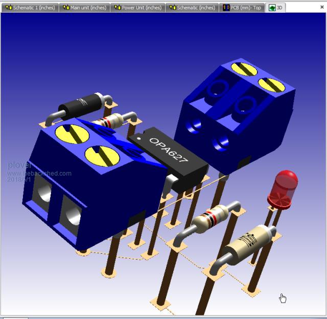 Below is how it looks from the top, bottom simlar no pads or tracks can be seen. 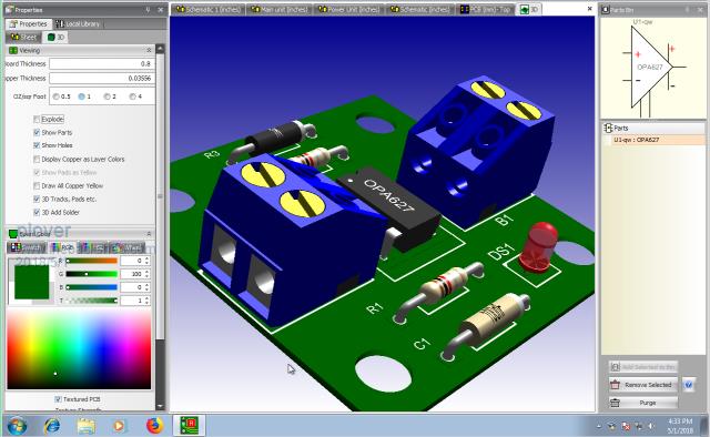 I was scratching my head over the 'small pads' until I realised what I could see was only the through plating cylinders. I will try to attach the DEX project file after zipping. 2018-05-01_172838_180501-Subshet-sch.zip Really that talks better than my explanation, what I would like to know is just me or is there a problem? While I am at it, for my own memory when I archive this thread, here is the background 'Q-Dir' setup to load individual files into my DEX testing library. This works very well but needs care because any click will launch a new DEX instance which may not be what is wanted. Certainly is easy to open a part if the pc system is powerful enough to handle it quickly. 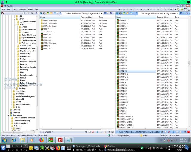 |
||||
| bigmik Guru Joined: 20/06/2011 Location: AustraliaPosts: 2870 |
Hi Plover, That ZIP file comes up as "404 NOT FOUND" Email it to me if you can bigmick58@bigpond.com Kind Regards, Mick Mick's uMite Stuff can be found >>> HERE (Kindly hosted by Dontronics) <<< |
||||
| bigmik Guru Joined: 20/06/2011 Location: AustraliaPosts: 2870 |
Hi Plover, There was an Embedded space in your URL so the ZIp didnt work, Here is the link Plover Project that should work OK. Now I can see your tracks fine without doing anything although your 3D for the screw jacks is missing.. I notice your tracks are still set to very thin, but I realise this is just a test. 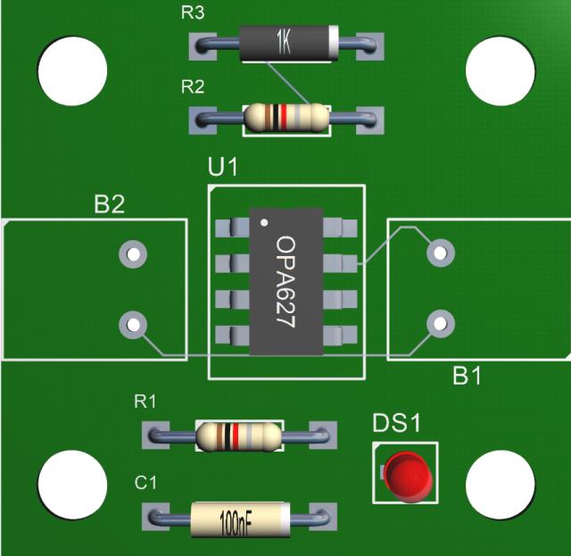 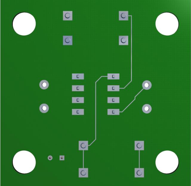 Kind Regards, Mick Mick's uMite Stuff can be found >>> HERE (Kindly hosted by Dontronics) <<< |
||||
| plover Guru Joined: 18/04/2013 Location: AustraliaPosts: 302 |
Hi Mick, I still can't get the tracks and pads to show in 3D (layout is fine of course). I went through your tutorial again last night and whilst the newer DEX versions have slightly different presentation I seemed to have the proper settings but then again I easily overlook something. I think, I am really struggling to remember what is where due to fluid nature of the Ribbon, context sensitive I think is the word. But hey Protel took many a moon out of my calendar as well I think it is the cost of high performance programs. Now focused on battling with parts making but are getting the hang of it, when I have finished a part with foot print, as soon as I make a 3D view I can see if the pads have come 'out of the ground'. So I will live with that until I figure out why as I will assume it is me having wrong settings. Yes I lost the footprints somehow on the two terminal blocks. That was a big surprise, could not find out where I got them from either as have too many places to look I guess. I have worked out to change library pass on the fly so I can link directly to the 'big cat1' file with goodness know how many parts, was it over 100,000 and in my present setup it takes about 30 seconds to connect. Status is that exploding a board always has the pads, they are just inside below the pcb surface. About the link, I will be careful next time and see what happens. Linux do not like spaces at all in file names and Windows don't care. I will look into it, not sure if I have seen a note somewhere to be careful with this on TBS. My local friend and pc wizard suggested last night when we were talking about setting up a RAM drive to be used fot the Windows TEMP and TMP locations to speed up drive access. We found out however at the same time that I had only allocated 2GB of RAM for Win7 in the Vbox and he was adamant that for 64 Bit system that was borderline, when looking at committed RAM of 1700 MB, I admit he is right. I thought I had allocated 3GB so anyway looking at getting another 8GB of RAM for the machine so I can run more than one VBox instance comfortably. Once you havea finished job, say you have used DIP component and decide to use SMC equivalent. That is you have the symbol for your component in the schematic. You just need to swap the footprint? How do you do that? I can do it but must be the wrong way as I screw up both the part and the schematic. Schematic looses all the wires connected to the symbol when I delete same that. I have found that I need to rebuild the symbol as when I try to add a new footprint to the existing symbol in the library. From what I can figure when I do that all the symbol termination points are taken from the old symbol and attached to a rectangular version magnet outline. Here talking about an op amp symbol getting a new symbol border when changing the footprint, which attracts all the terminal points so rebuild of symbo needed . Oh what fun  I will see if I can add visual example, just trying this on a transistor symbol but seem to get stuck unable to get partbuilder to recognise symbol. |
||||
| bigmik Guru Joined: 20/06/2011 Location: AustraliaPosts: 2870 |
GDay Plover, I simply cannot reproduce the `unseen tracks' No matter what I do. in the 3d View play with all the PROPERTY settings like 3D tracks, Copper as layer color, pads as yellow and see what happens. It might be lack of memory on your 3D graphics card.. As to SMD-THP .. yes you can do it but I know what you mean about the schematic being upset to plain boxes.. What I do is copy the part to a new one and then in PCB select SUB Pick and select all pads in turn using SHIFT-CLICK (or is it CRT-Click) and then in Properties change them to SMD (and adjust shape/size) and then unselect and adjust the positions one by one until happy. \ Then save them as a new SMD part. As I have said DEX has some eccentricities but you do get used to the way things work and learn to adjust the way you do things. Be wary of the bulk parts library as there are MANY mistakes, especially hole sizes.. I generally do not use any in the lib but create my own from scratch. (More often I use a similar part with same number of pads and copy it to a new part and then edit that part to suit.. I really struggle getting what I need many times using the part wizard,) When you added the 3D to the terminal jacks did you save the part? There might be an obscure bug there as when I created the RJ12 on DEX forum I found the 3D was missing. I swear I clicked on the little floppy image to do a sve and so I did it again and the 3D did not save again.. I then clicked on the DEX symbol on TOP LEFT and selected SAVE from the menu and this saved the part.. I havent tried reproducing it.. As for your Link not working.. I bet you first copied it as plain text on the forum and them cut and pasted it from there into the Hyper-Link tool. TBS forum adds random spaces in long strings of text (for some unknown reason). Kind Regards, Mick Mick's uMite Stuff can be found >>> HERE (Kindly hosted by Dontronics) <<< |
||||
| plover Guru Joined: 18/04/2013 Location: AustraliaPosts: 302 |
Went through the relevant sections in your tutorial again and explored the properties window more closely, trying more things and started expeimenting with pcb colouring and transparency. I noticed whenever I changed the colour for about just under one second the the layers will show and then disappear. Would be all yellow if that option ticked or it would be blue/red colouring so it looks like trarcks and pads work fine. Further when the 3D window is in the open viewport the picture flicker, as if a fast redraw takes place. Got more curious about the transparency slider as it did not seem to have any effect except for the very very left position where the board material gone all together and only the X-ray part is left, rather impressive. When I have the Library pane open, focus on say my LM311-N comparator chip, in this case I built the part rom the ground up with Partbuilder with success. Library shows nicely the little 'Package' (3D) as below, I notice the pads are correct on the board, ie showing. If I now open the 3D viewport, the library 'Package' window is locked up. I think clearly the 3D plays a part in my problem. I have changed the VBox vitual machine to have more RAM, just over 3G and I added wore graphics memory, 128 MB plus added another processor so it is running total of 2. (I think I can add another two on this system but for testing I am happy with 2 eases the resources.) I had at least 3 severe crashes, not just Windows locking up but the VM closing down completely. At least now I know that by playing with the 3D graphics and transparency changing on off I seem to get a crash very shortly. I am leaning towards the VBox as the weak part, also what I am least comfortable with as it is completely new to me. So today I am going to look at the VBox logging. 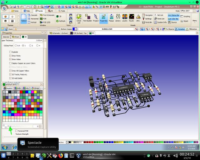 The green arrow marks the very end of the Transparency slider, and at a guess 2 seconds away from something going to crash. Ok, about the parts changing yes we both seem to have trouble with that. Regarding the link I no longer remember how I did that, at the time it seemed easy enough. It certainly does not work, I thought it might have been the underscores which shows up as spaces if not carefully looked for. |
||||
| plover Guru Joined: 18/04/2013 Location: AustraliaPosts: 302 |
While looking at the pcb of a circuit I noticed the grid and rulers do not agree, ther is a linearly increasing distance between grid and rulers away from origo of (0,0) Have tried to show the difference at 2" vertical distance, I have not done the calculation but I am wondering if it has anything to do with the imperial/metric conversion. I do not know but wonder if imperial 1''' (Thou) is the base unit and the metric are conversions. Anybody noticed? 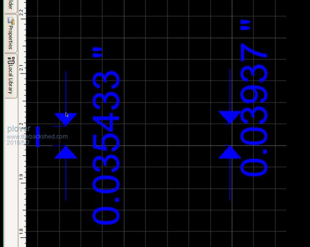 I have marked a segment as best I could do with my mouse, indicating the error at 2" major grid line mark. I have also showed difference between two minor grid lines which should be 0.040" or 40 Thou |
||||
| plover Guru Joined: 18/04/2013 Location: AustraliaPosts: 302 |
The following is just a reminder to myself when I make archive of the topic, for later use. I saw this earlier but could not fine the video again. Then I was looking in the 2017 list of version updates and saw that Feb 2017 DEX update had component replacement. (Not for Multipart Symbols) The trick is, in the Schematic you highlight the symbol first, then drop another the replacement symbol on top of the highlighted old symbol. If succes a window opens and let you fix up connections that may not have been auto connected properly. To me the gain is you keep your wiring connected so less chance screwing up your wiring. If I need to redo them from memory not good. The following example is experimental part creation of a LM311-N and to help getting pins correct I inserted a picture of the pin out. I did try the transfer of pin out text with the copy from pdf arrangement via the clipboard but I failed. Have not worked out why. Here follows the sequence of pics. 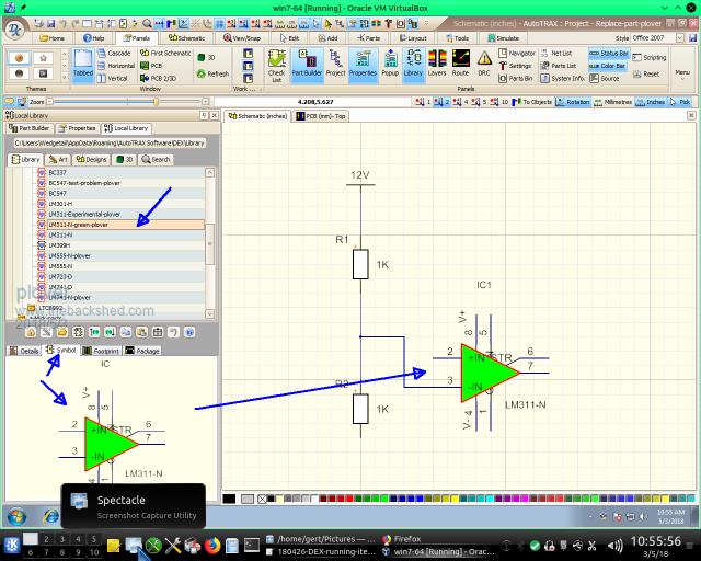 Above is the 'the old' component, in this case want to replace the symbol, which is highlighted, hard to see but must be. 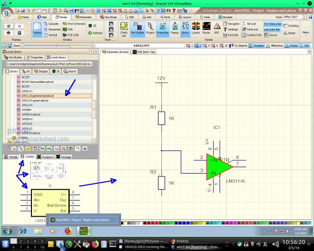 Above is the the new symbol selected in the libray but not placed in the schematic yet 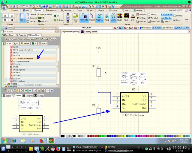 Above after dropping the new symbol, if success the connection check/update window option opens as shown below. 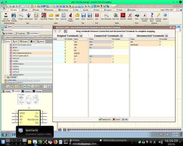 Here wiring ocrrections can be made before final schematic shown. 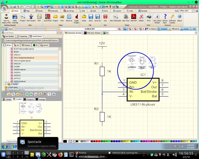 Here just drawing attention to how the part can have a picture attached and it will of course follow into the schematic. I am looking forward to using this, to replace foot prints which I have not yet proven. |
||||
| bigmik Guru Joined: 20/06/2011 Location: AustraliaPosts: 2870 |
Plover, All, The Autotrax Forum has moved to Google Groups.. The new home is here: AutoTrax Forum There Iliya states he is dropping support for XP.. He is wanting responses. Personally I dont ever want to go back to XP so it wont impact me, it may be an issue to you though.. Kind Regards, Mick Mick's uMite Stuff can be found >>> HERE (Kindly hosted by Dontronics) <<< |
||||
| plover Guru Joined: 18/04/2013 Location: AustraliaPosts: 302 |
Thanks for that XP information, then I can forget about experimenting with the small XP footprint. My local pc wizard showed me how small RAM footprint needed. I was expecting that DEX would run lightning on XP. Good news from me, though I was getting rather frazzled. First after having set up a another VM on the hard disk proper in case the USB3 port and external hard drive in docking station was a factor in the crashing problems. Setting up the new VM was a hazzle but did remind me of being carefull in the Guest Additions about selecting 'aero' graphics option, of sourse I had to try and it did work mostly but also became unacceptable to me. After a couple of hours I re-installed the GAs and did not select 'aero' and I can say it is probably best ignored for beginners if you are not crash hot on Windows install what 'aero' does. (I am not good at windows any longer, forgotten too much) When DEX finally got up and running it was quickly established that pad and tracks had gone underground. Hours went by and one good thing I established that the graphics seemed very stable at lest I had real trouble crashing the system (but did succeed once). I went over and over the icons again and when I got to 3D ribbon part I found a solution. The following picture has 3 arrows pointing to 3 icons, the two on the right on my system have a blue colour when selected, ie 'Perspective' is blue meaning it is selected and active. Same goes for the right hand arrow, 'Single' view-port in 3D is active. The left hand arrow point to '3D Copper' and it is blue, ie I assumed it is active and should show the copper on the 3D picture. It is not so I click on it but still no copper. Clicking on the icon toggles it Blue / Not Blue and here is the trick turn it off ie not Blue and then hit the 'Refresh' just below and the copper shows up. I can not figure out if there is a reason why the '3D Copper' Icon alone should not be toggling the copper on and off, seems a good logical choice. 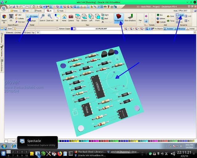 On the following picture clearly seen that '3D Copper' no blue colour and the copper is showing on the 3D picture. 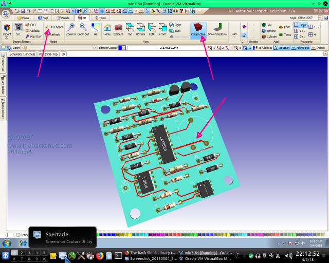 I have selected a 'skin' that shows the '3D Copper' icon fairly big to demonstrate my solution. Other skins have much smaller icons such as '3D' and then you need to know what that button actually do, if you do it is not a problem to use smaller icon. I mention that because I accidentally found out that selection of skin on my system is very important for the 3D stability depending on what windows/Tabs are open are open Following presentation of TABs an viewport can be very disturbing on my system and may be because I run DEX in VM Guest Win 7-64 bit I don't know bur now I know to be a bit careful with what I want to see. The following combination can really give my 3D viewport the jitters when I move the mouse over the footprint shown. There are a number of combinations of docking arrangements that most likely will crash my system but now I am aware of what goes on and where I expect to be able to avoid those combinations. 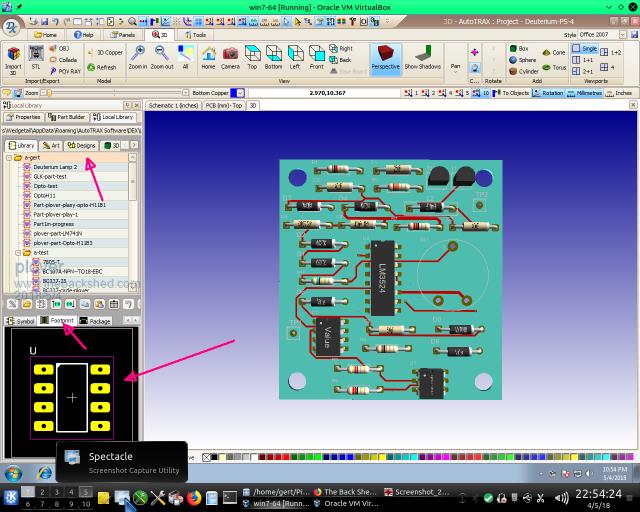 The surprising thing is that I feel there is a distinct speed of operation difference between the external drive and the internal, so the USB3 port is not a hold up as such. So I am back on the external drive to continue with Schematic work. I have got an assembly of 'bigmik' parts from various posts and will work my way through those as learning exercise. |
||||
| plover Guru Joined: 18/04/2013 Location: AustraliaPosts: 302 |
Seems that when making parts soon the need for 3D knowledge is required. Can't be that difficult as I have a big 3D program but it seems there is a problem. Not sure what it may be at this stage. First when I am in DEX 3D or I think I am, I have a blank schematic and blank pcb as starter and start off with the 3D of the blank pcb, nice green 'slate' when trying to place object as seen here on the next pic 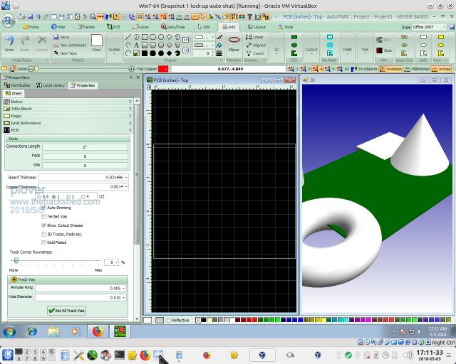 I have my 3D objects but no indication of those being cut by the pcb, pcb window no sign of objects such as what I see in the video I watched as follows 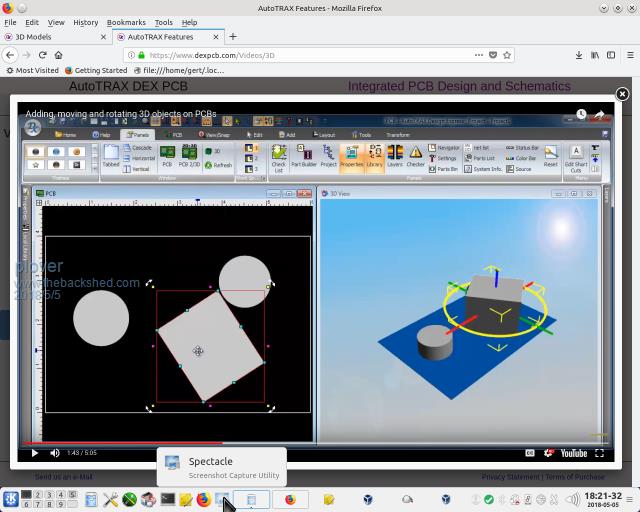 Two things, in the first picture as soon as I click on an object in the ribbon the mouse pointer disappears when crossing into the 3D window so I hve no indication of where I am relative to the green board but as it can be seen I can sill generate the object. The second thing, when placed I can not move the objects. Right click to use 'Pick' will sometimes show the 'Pick option' if so the picture will shudder and blink but return without the nice Axis guides seen in picture 2 A concern as it seems straight forward in the video. No sign of the mouse pointer missing temporarily. There may be something related to the skins not sure. I just noticed my first picture is not really showing the 3D ribbon section, here is where I first created some objects 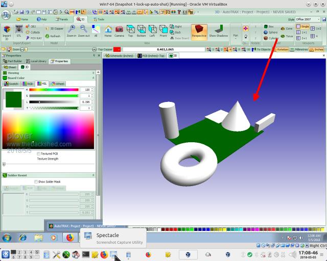 Anybody got suggestions where I am going wrong. |
||||
Chopperp Guru Joined: 03/01/2018 Location: AustraliaPosts: 1032 |
Hi Bigmik Can't get the link to work ChopperP |
||||
| plover Guru Joined: 18/04/2013 Location: AustraliaPosts: 302 |
Chopperp That is interesting, it did work when it was first posted. I visited and found there was only 5 entries, the last one from Ilya about XP. |
||||
| Chopperp Guru Joined: 03/01/2018 Location: AustraliaPosts: 1032 |
Hi Plover Comes up with:- There is no group named �autotrax� What URL comes up when you click the link? ChopperP |
||||
| plover Guru Joined: 18/04/2013 Location: AustraliaPosts: 302 |
I do not understand I run the latest version of DEX and the 3D to me seems to be quite a number of generation back. This of course makes no sense since the cideo demonstrations clearly show that 3D objects can be handled in 3D window. The mouse seems unable to 'grib' any of the objects in 3D. Took a long time before I realised that limited 3D operation can be done in the 2D or pcb window. Focus on pcb window, and selct the ADD TAB in the ribbon see following pictures 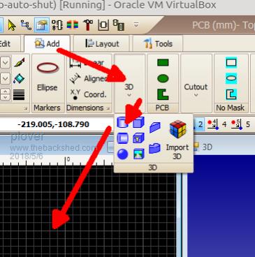 Shown is path I follow to place a cylinder position in the PCB window 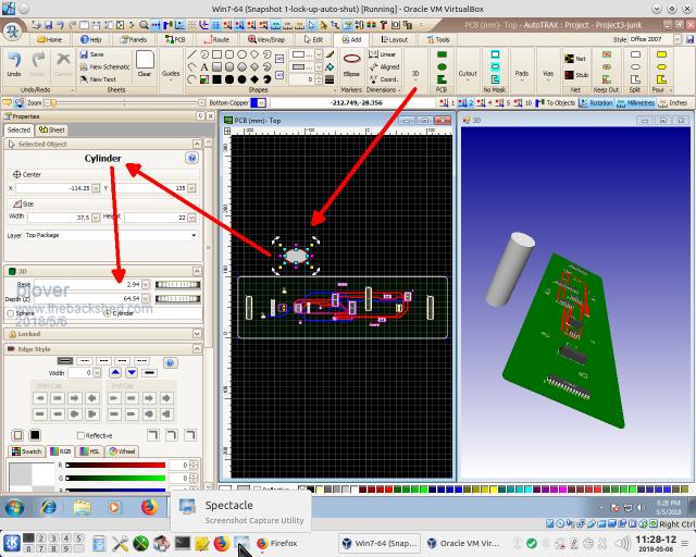 I can then move this cylinder around in the 2D window and watch action in 3D window. To change cylinder dimension use the two wheel fields, I spin the mouse wheel i the numeric field rather than using the graphics wheels which I think perhaps should be used for precision changes. 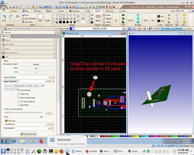 I can only think that my mouse is not suitable, it is only a 2 button plus wheel (recommended is 3 button) or it is because I am running VBox Guest Win7-64. |
||||
