
|
|
Forum Index : Microcontroller and PC projects : MM programmer/debugger 1A...
| Page 1 of 3 |
|||||
| Author | Message | ||||
Grogster Admin Group Joined: 31/12/2012 Location: New ZealandPosts: 9975 |
I found that more and more these days, I need to have both the ICSP pins AND the console pins at the ready. To ease my stress level having to keep reconnecting things between ICSP mode and console mode, I decided to build a special programmer/debugger tool.  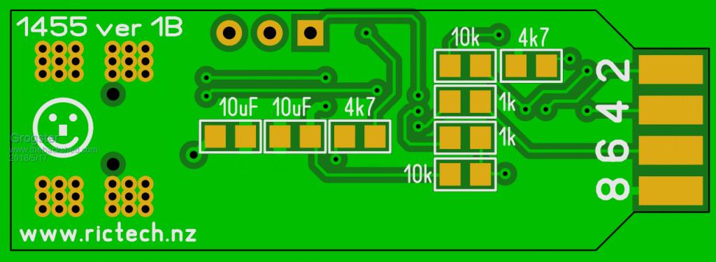 The board is 43mm x 15mm so quite small. The 1455 chip is SSOP. All passives are 0805, regulator is SOT-223. It was after I ordered them, that I thought that the SOD-123 diode on the 3v3 line is probably pointless, as the 3v3 pin will actually be around 2v7. The idea was to stop an externally powered circuit from coming back into the output of the programmer regulator. The 1455 chip does not care about the 3v3 line like the Microchip PK3 does, so I guess it does not matter that much. The business end of the unit has a 2x4 female header mounted with the board in the middle of the two rows of pins. This could be male, and the boards female if preferred, this is just how I do it. It is a standard 2.54mm 2x4 header with the following pinout: 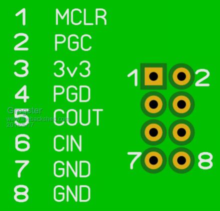 What I like about having the ICSP and the console on one common connector, is that you can program the HEX into the MM using the ICSP pins, and also talk to the console on the same header, all via the one unit. This saves a lot of wire-swapping between ICSP and console on boards that DON'T have the 1455 incorporated. And cos the 1455 chip automatically drops out of ICSP mode back to serial mode when it has finished programming the HEX into the chip, as soon as that is done, you can just open the COM port and start talking to the console without having to change anything.  If there is any interest in this, I can build a constructors pack and publish it on my website so others can download and build their own. Just let me know on this thread if you want me to do that. EDIT: Fix spelling mistakes.  Smoke makes things work. When the smoke gets out, it stops! |
||||
CircuitGizmos Guru Joined: 08/09/2011 Location: United StatesPosts: 1427 |
 Micromites and Maximites! - Beginning Maximite |
||||
| Grogster Admin Group Joined: 31/12/2012 Location: New ZealandPosts: 9975 |
HAHAHA!!!  Smoke makes things work. When the smoke gets out, it stops! |
||||
Chopperp Guru Joined: 03/01/2018 Location: AustraliaPosts: 1126 |
Hi Groggs It took me ages to work out what was going on here. I think I get it. Bit slow!!! There is a double row of male header soldered to the end of the main board with the board between them & they plug into female headers on the MM board which has the ICSP & Console pins wired up as per the "Business End". Is that correct? Also I: Is it possible for your bottom board photos be flipped / rotated end to end. It may make it easier for me to mentally line up the top & bottom components & tracks etc. Also II: How do you load the HEX file using the 1455? Thanks. BTW, you got your workbench tidy yet? ChopperP |
||||
| Grogster Admin Group Joined: 31/12/2012 Location: New ZealandPosts: 9975 |
I do it with a female(what?!) header on the unit, and male pins on the project, but you can have it with male pins on the unit, and female header on the project - up to you. The board images are flipped horizontally, as that is how you would look at the board, if you turned it over horizontally. How about an image showing both layers: 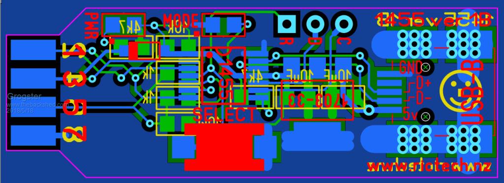 The 1455 is both a USB-serial adaptor for the console, and also a programmer so you can load any new HEX file into the PIC32 chip at the heart of the Micromite, without having to use the Microchip IPE(and it's massive IDE download) or a PicKit-3 programmer tool. Press the SELECT button to put the unit into ICSP mode, and program your HEX file firmware into the PIC32 chip. EDIT: Workbench? What's a workbench? I can't see any workbench for the mess!  Smoke makes things work. When the smoke gets out, it stops! |
||||
| Chopperp Guru Joined: 03/01/2018 Location: AustraliaPosts: 1126 |
Thanks Groggs Not sure with both images together. What do you use to upload the HEX file with? Can it be done with MMEdit? ChopperP |
||||
| Grogster Admin Group Joined: 31/12/2012 Location: New ZealandPosts: 9975 |
Here are both images just for you.  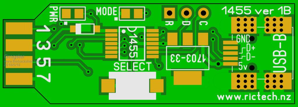 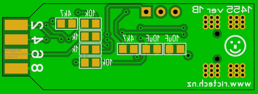 To upload a HEX to a PIC32 chip, you use the 1455 as the programming tool, and PIC32PROG.EXE, which is a command-line programmer co-developed by robert.rozee and Serge Vakulenko. Rob write a nice little GUI for the front-end, so you can do it all with just a few mouse clicks: 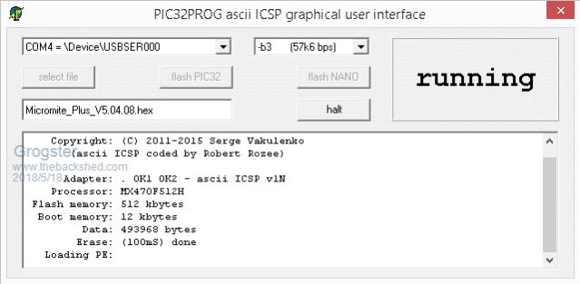 The procedure is: 1) Connect the 1455 to your Micromite chip 2) Press SELECT button to put the 1455 into ICSP programmer mode(LED lights) 3) Run pic32prog GUI, select HEX file and COM port that the 1455 is on 4) Click "Flash PIC32" That's all there is to it. "Flash NANO" is an option for the original concept that used an Arduino Nano as the basis of the programmer. You could click this button to load the code into the NANO module to make the programmer work. You can safely ignore that button, as we don't use it anymore. Smoke makes things work. When the smoke gets out, it stops! |
||||
| Chopperp Guru Joined: 03/01/2018 Location: AustraliaPosts: 1126 |
Ah, thanks very much Groggs for both the images & the instructions. I have seen the program mentioned now & then. Leave you to your bench clean up ChopperP |
||||
plover Guru Joined: 18/04/2013 Location: AustraliaPosts: 306 |
Grogster I am very interested in a kit (even fully built but for the connectors in case a swop is needed when I get to the point of using it. count me in. |
||||
| robert.rozee Guru Joined: 31/12/2012 Location: New ZealandPosts: 2528 |
have you thought of integrating a USB plug into the PCB? either a real plug, or a 'tongue' as part of the board. btw, it is probably more accurate to say that serge wrote pic32prog, while i just wrote some extensions to a small part of it :-) and even then, i was working closely under serge's guidance. cheers, rob :-) |
||||
| Grogster Admin Group Joined: 31/12/2012 Location: New ZealandPosts: 9975 |
No, not really. I don't see the need. In that situation, you WOULD be able to plug the thing directly into the USB port on the host, but then it would be fiddly to get the thing you wanted to program or talk to, to connect to the other end. I stand corrected on the pic32prog.exe note. Serge wrote a brilliant bit of utility exe in pic32prog and your enhancements make it a joy to use to program MM chips.  Smoke makes things work. When the smoke gets out, it stops! |
||||
| Grogster Admin Group Joined: 31/12/2012 Location: New ZealandPosts: 9975 |
The PCB's for this have arrived. I hope to build one in the next few days. Photo of a PCB shown with a PK3 for size comparison: 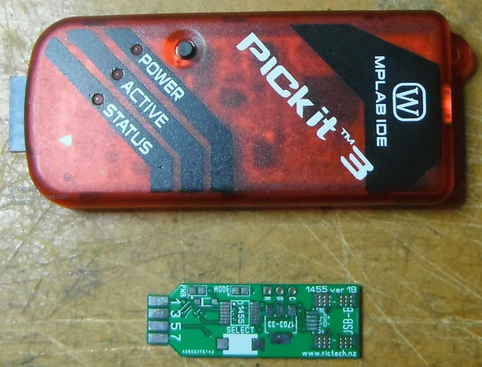 Smoke makes things work. When the smoke gets out, it stops! |
||||
| Grogster Admin Group Joined: 31/12/2012 Location: New ZealandPosts: 9975 |
Updated version 1B2 with standard 5-pin 2.54mm ICSP holes for easy programming of the 1455 and a couple of other minor layout tweaks.   Shown with a PicKit-3 as a size comparison. Smoke makes things work. When the smoke gets out, it stops! |
||||
bigmik Guru Joined: 20/06/2011 Location: AustraliaPosts: 2981 |
GDay Grogs, This looks interesting.. but you have me a bit confused as to how it plugs into a standard 6 pin SIL header? The pinouts do not seem to lend itself for that and look like they require jumper wires to connect to your device Regards, Mick Mick's uMite Stuff can be found >>> HERE (Kindly hosted by Dontronics) <<< |
||||
| Grogster Admin Group Joined: 31/12/2012 Location: New ZealandPosts: 9975 |
It doesn't. The ICSP 5-pin is there just so you can program the 1455 using a PK3.(ignore pin 6) Once programmed, you don't use the PK3 anymore, you use the little board as a MM programmer and debugger unit. The 2x4 female header at the left end in the photos, contains all the connections for ICSP and also the console, so you can program new MM chips AND have the console connected all at the same time. I got sick of swapping wires around between a PK3 and a serial module for the console, so built this thing which does both at the same time thanks to the 1455's ability to do both. I have now started using a 4x2 pin-header on all my projects. It is reasonably small, and gives me the ICSP and the console in the one pinout. EDIT: Here is a photo of how it plugs into a board:  With the ONE connection, I press the SELECT button on the little programmer/debugger thing, program in the MM HEX file. Once that is done, the programmer drops back to serial port mode, and I open a COM port to it - all without having to change anything or move any wires. Smoke makes things work. When the smoke gets out, it stops! |
||||
| CircuitGizmos Guru Joined: 08/09/2011 Location: United StatesPosts: 1427 |
If it were a 5x2 header then one side could be the standard ICSP lines, the other side would be the console com port lines. People with the standard 1x6 header could still make use of your board. RST . VCC RST GND RxD PGD GND PGC TxD (NC) A 2x5 on your board and the target gets you everything. Same with a 2x4 shifted down. 1 1x6 (really 1x5) on your board works with old boards that have 1x6 ICSP. The console com port can be used with a 1x3 header. Micromites and Maximites! - Beginning Maximite |
||||
| Grogster Admin Group Joined: 31/12/2012 Location: New ZealandPosts: 9975 |
I did that kind of idea in version 1A of the PCB, but it was ugly and I ended up with wires coming off the pins on the top of the board. Did not like it.   I hear what you are saying though. Perhaps a version 1C along the lines you mention....... Smoke makes things work. When the smoke gets out, it stops! |
||||
| CircuitGizmos Guru Joined: 08/09/2011 Location: United StatesPosts: 1427 |
Now would be the time to change before the other layout propagates onto other target boards. I will admit that I used your 2x4 layout on a board (even though I don't have your programmer) and it was nice to leave the programmer /slash/ com port USB board in place. The layout I suggest gives backward compatibility for those many boards with the 1x6 (1x5) standard ICSP, yet you can center a 2x4 and get the Grogster benefits. It makes your board and the one I made obsolete... Micromites and Maximites! - Beginning Maximite |
||||
| CircuitGizmos Guru Joined: 08/09/2011 Location: United StatesPosts: 1427 |
Perhaps this would be ever so slightly better? Or allow for vcc to be 3V (normal) or 5V with a jumper? RST 5V VCC RST GND RxD PGD GND PGC TxD 1x5 gets you standard ICSP. RST VCC GND PGD PGC 2x4 gets you GrogPort 2.0. Different pin arrangement from GrogPort 1.0. VCC RST GND RxD PGD GND PGC TxD Micromites and Maximites! - Beginning Maximite |
||||
| CircuitGizmos Guru Joined: 08/09/2011 Location: United StatesPosts: 1427 |
Vcc selection via 1 1x3 header. 5V Vcc (to ICSP) 3V Jumper on pin 1 and 2, Vcc is 5V Jumper on pin 2 and 3, Vcc is 3V No jumper, target board is powered by itself. Micromites and Maximites! - Beginning Maximite |
||||
| Page 1 of 3 |
|||||
| The Back Shed's forum code is written, and hosted, in Australia. | © JAQ Software 2026 |
