
|
|
Forum Index : Microcontroller and PC projects : pi zero w
| Page 1 of 2 |
|||||
| Author | Message | ||||
palcal Guru Joined: 12/10/2011 Location: AustraliaPosts: 2039 |
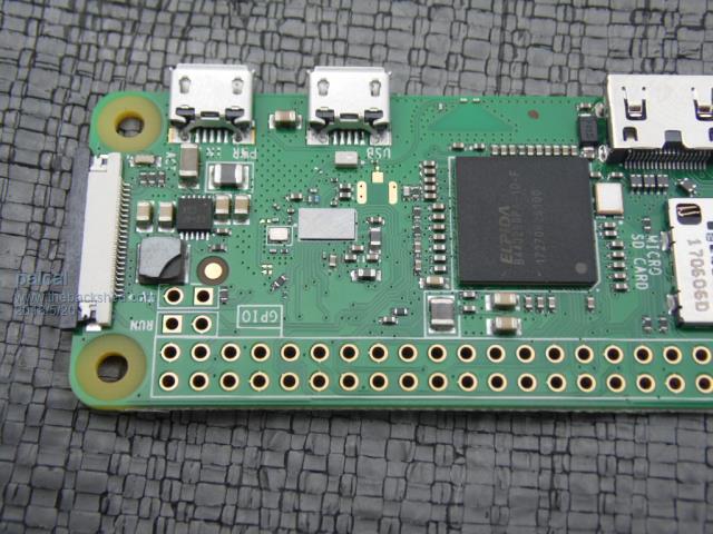  Does any one know what the chipped part is. I have found a picture where it has 4R7 printed on it so I am assuming it is a 4.7 ohm resistor and by its size maybe .5 watt, I thought maybe someone could confirm that. I received this board damaged and the seller is sending a replacement so I thought I would see if I can repair this one. Paul. edit... When I first applied power the green led fickered but now nothing so I am thinking it is a resistor in the power supply circuit. I can't find a pi zero Schematic anywhere. edit again.... the reason the led stopped fickering was because I had removed the sd card. I know nothing about pi zero the led flickered for a while and now it is on steady, was it reading the card. I will have to find a tutorial somewhere. "It is better to be ignorant and ask a stupid question than to be plain Stupid and not ask at all" |
||||
| PeterB Guru Joined: 05/02/2015 Location: AustraliaPosts: 669 |
G'Day Palcal I know even less about Pi Zero but I decided to have a look while the washing gets done. From what I have discovered, earlier versions had an inductor in that place and the W version clearly shows a 4R7. I think it's time for the next load. Good luck. Peter |
||||
plover Guru Joined: 18/04/2013 Location: AustraliaPosts: 306 |
palcal My opinion is also it ought to be a 4.7 ohm resistance high power, then again I believe there are inductors looking like this, find buckets of them in a laptop, I should have been able to remember better. Will see if I can chase something up. In the mean time, have you checked with a multimeter to make sure there is conductivity as you should have independent of being R or L of course may be you need to remove it to be absolutely sure. Yes circuit diagram would be nice, just did a quick look on the internet, here is a pic from some work I did trying to repair a laptop. Sorry about details but it gives an idea of what an inductor may look like They may have more writing than a resistor upon them. PL are inductors, some mosfets above give size idea 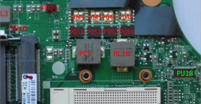 |
||||
| ryanm Senior Member Joined: 25/09/2015 Location: AustraliaPosts: 203 |
I believe that you'll find it's a 4.7uH inductor. The layout with the IC next to it is textbook switching power supply. |
||||
Grogster Admin Group Joined: 31/12/2012 Location: New ZealandPosts: 9975 |
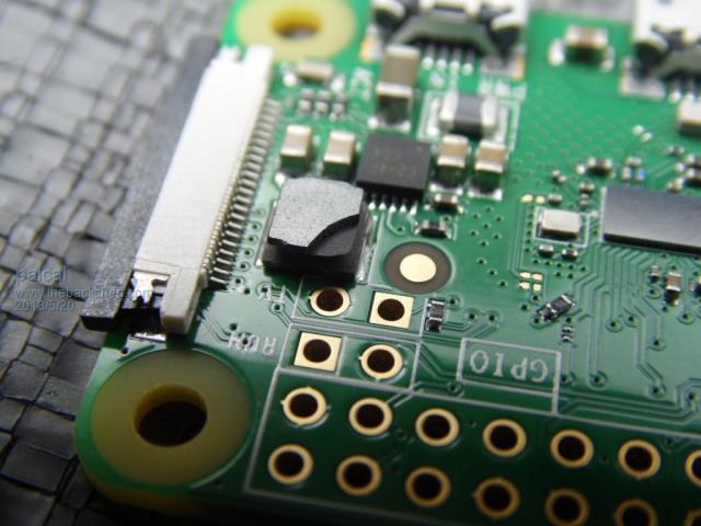
I tend to agree with ryanm. When I looked at my Pi-0 under the microscope, you can clearly see that there is enamelled wire going in one side, and coming out the other. It is sealed up in black gunk, probably to stop any HF resonance from being heard. Smoke makes things work. When the smoke gets out, it stops! |
||||
bigmik Guru Joined: 20/06/2011 Location: AustraliaPosts: 2981 |
Hi Paul, I dusted off my Pi-W and the PCB looks identical to yours except for the broken component, Mine has a clear marking of 4R7 in black printed on the device. Mine has a short across it and connects directly to pin 1 of the header which is 3v3. My guess is it has to be an inductor of 4R7 micro-Henry (??? not sure but I think it might be u-Henry) I reckon you could safely short it out. Kind Regards, Mick Mick's uMite Stuff can be found >>> HERE (Kindly hosted by Dontronics) <<< |
||||
| paceman Guru Joined: 07/10/2011 Location: AustraliaPosts: 1329 |
Hi Paul, Just looked at my Zero-W (which I've yet to fire-up) and I think the 4.7 device is more likely a 4.7uH inductor. Reason is that the 12 pin chip alongside it is a 2306KE (just managed to read it with a magnifier) which is a step-down regulator so that needs an inductor and the smd versions of them look like that one. There's some info on the Pi forums and RPi Stack Exchange here but not a direct answer for you. Greg |
||||
| ryanm Senior Member Joined: 25/09/2015 Location: AustraliaPosts: 203 |
I wouldn't be surprised if it still works once you've loaded an OS onto the SD card. Loosing a chunk of ferrite material will alter the inductance a bit, but I can't see any coil broken. SMPS usually have a fair bit of tolerance for varying inductance values and the chip brand new out of the factory would only have had an accuracy in the +- 20-30% range. |
||||
| bigmik Guru Joined: 20/06/2011 Location: AustraliaPosts: 2981 |
Hi Paul, Here is a photo of my Pi-W 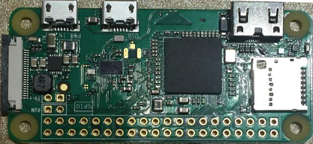 Kind Regards, Mick Mick's uMite Stuff can be found >>> HERE (Kindly hosted by Dontronics) <<< |
||||
| bigmik Guru Joined: 20/06/2011 Location: AustraliaPosts: 2981 |
Paul, It is almost certainly similar to this device RS Components link Kind Regards, Mick Mick's uMite Stuff can be found >>> HERE (Kindly hosted by Dontronics) <<< |
||||
TassyJim Guru Joined: 07/08/2011 Location: AustraliaPosts: 6538 |
Schenatic of the pi zero W power supply areas. 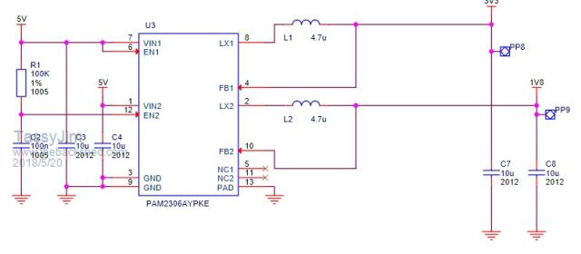 Extracted form https://www.raspberrypi.org/documentation/hardware/raspberrypi/schematics/rpi_SCH_ZeroW_1p1_reduced.pdf 4.7uH stands out as a likely suspect. Jim VK7JH MMedit |
||||
centrex Guru Joined: 13/11/2011 Location: AustraliaPosts: 320 |
Why not just load noobs on a micro sd card plug in a monitor you may need an adaptor plug in the sd card pins facing up connect 5v power and see what happens. Noobs is an iOS file from raspberry pi downloads. The pi zero w works well. Cliff Cliff |
||||
| palcal Guru Joined: 12/10/2011 Location: AustraliaPosts: 2039 |
Thanks for all the replies, after that I am sure it is an inductor, I didn't think they used R with an inductor but there you go. Looking closely at the broken component it sure looks like ferrite. However I burnt an SD card with Raspian stretch and the blinking LED seems to be the file loading, after a while the LED settles down solid green. So I think all is OK. I was like a kid with a new toy and instead of reading a tutorial I just started connecting it up. But need a USB hub and an adapter cable for the monitor. I really only bought it to play with the Picromite but now I think I will play with it a bit more first. Paul. "It is better to be ignorant and ask a stupid question than to be plain Stupid and not ask at all" |
||||
| matherp Guru Joined: 11/12/2012 Location: United KingdomPosts: 11512 |
You can do everything headless by connecting from your PC. You can also set up wireless access so that the Pi will connect to your network Have a look at his site. You set up the file "wpa_supplicant.conf" on your PC and copy it to the boot partition on the Raspbian SD card. Also create an empty file "ssh" and copy it to the boot partition. Then put the sdcard back into the Pi and boot it. The pi reads wpa_supplicant.conf and automatically configures its wireless access as defined in the file. The file "ssh" tells it to enable remote ssh access. Then the pi will be connected to your wireless network and you can access it using teraterm or putty |
||||
| lizby Guru Joined: 17/05/2016 Location: United StatesPosts: 3784 |
Headless is good. I had one R-PiZW (out of maybe 6) which wouldn't come up headless over wifi with the wpa_supplicant.conf change. I got RX and TX working (through usb/serial--3V3 only) with a raspbian stretch lite OS by adding "enable_uart=1" at the end of the file "config.txt". On a linux device, after mounting /dev/sda1, use "sudo nano /boot/config.txt". With the SD card in an adapter on a Windows PC, I think the SD is named "boot", and the config.txt file is in the root of the SD. (Also still needs the empty "ssh" file. Login is "pi" and "raspberry".) PicoMite, Armmite F4, SensorKits, MMBasic Hardware, Games, etc. on FOTS |
||||
| palcal Guru Joined: 12/10/2011 Location: AustraliaPosts: 2039 |
Thanks for that, will give it a try. Paul. "It is better to be ignorant and ask a stupid question than to be plain Stupid and not ask at all" |
||||
| palcal Guru Joined: 12/10/2011 Location: AustraliaPosts: 2039 |
Part 2 of my Ladder Black Cat and Mirror saga. I got all the connectors for my Pi so flashed the SD card and away it went I was amazed at what this little board can do. Mouse worked but keyboard no go, so I bought a wireless mouse/keyboard combo and it works fine. But I had no wireless. I had copied the wpa_supplicant.conf and ssh files to the card but only after booting the card once or twice. Then I read that the files had to be added after flashing the card before first booting it. So I decided to format the card and start again then during flashing the power went off. So in the afternoon when power was restored I flashed the card, added the files put the card in the Pi and fired it up. You guessed it the bloody power went out while it was booting. Next morning... Tried again but now after it boots the screen keeps turning on and off every few seconds. Paul. "It is better to be ignorant and ask a stupid question than to be plain Stupid and not ask at all" |
||||
| palcal Guru Joined: 12/10/2011 Location: AustraliaPosts: 2039 |
So I removed the SD card and the 2 extra files I put there were gone. So I re flashed the card again and this time I created the files from within the SD card. At last I got onto the internet but the screen still keeps blacking out, would a faster SD card help. It is not the Pi board, I have 2 and tried them both. Paul. Edit... Just checked the card and it is Class 10 so it is not the speed, it is 8gb would more memory help. "It is better to be ignorant and ask a stupid question than to be plain Stupid and not ask at all" |
||||
| palcal Guru Joined: 12/10/2011 Location: AustraliaPosts: 2039 |
OK found the problem, if I turn off wi fi all is ok. Could it be a power problem, I have used the computer USB for power and also a mains USB charger. Paul. "It is better to be ignorant and ask a stupid question than to be plain Stupid and not ask at all" |
||||
| TassyJim Guru Joined: 07/08/2011 Location: AustraliaPosts: 6538 |
A bare board will draw 150mA. PC USB is very likely to have problems. They recommend a 1.2A power supply. Jim VK7JH MMedit |
||||
| Page 1 of 2 |
|||||
| The Back Shed's forum code is written, and hosted, in Australia. | © JAQ Software 2026 |
