
|
|
Forum Index : Microcontroller and PC projects : Large 7 segment displays - YAC
| Author | Message | ||||
| viscomjim Guru Joined: 08/01/2014 Location: United StatesPosts: 925 |
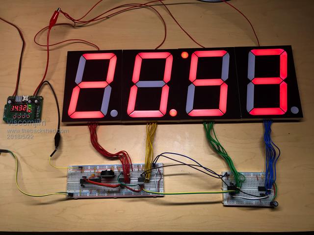 Working on a project for a buddy and he needed to drive some 5" red seven segment displays for a up/down timer. He got a bunch of them for about five bucks a piece. With a bit of googlizing, I found some really neat 7 segment drivers that can supply constant current to each segment with a SINGLE resistor... , not one on each output, just ONE resistor total. TLC5916 . Because these displays used 14 leds on each segment (2 x 7) and only 3 on the decimal point, I had to add one more resistor on the DP output to drop the voltage for this weird setup. The TLC5916s can go up to 20vdc, thankfully, because these displays needed about 14.5vdc to fire up. They are shift registers so you can use SPI mode 3 and make using them very easy. I have hooked up 4 of them and naturally, had to make yet another clock, for testing purposes of course. I took the 3rd digit and rotated it 180 so that the second and third digits decimal points could form a colon of sorts. The micromite makes this YAC project very easy, a DS3231 module, 4 TLC5916s and you're off and running. The verion 1.0 of my simple test program is only 27 lines of BASIC and shows me the time. Now I just need to add some buttons and a bit more code to be able to set the clock, set 12/24 time, dim the displays using the OE pin on the TLC5916, etc. For this simple test, I just set the time using the console to begin with. Here is V1.0... if anybody has an interest... Option AUTORUN ON 'Run on power-up SetClock 'call subroutine to load MicroMites clock with time from DS3231 SetPin 15, DOUT 'latch enable for TLC5916 Pin(15) = 0 'Set latch enable pin low 'Array to turn on combination of 7 segments for each digit - 0 to blank display Dim DIGIT(10) = (126, 20, 103, 55, 29, 59, 123, 22, 127, 31, 0) SPI open 500000,3,8 'SPI channel - 500khz, mode 3, 8 bits at a pop SetTick 60000, SetClock, 4 'Interrupt to fetch DS3231 time every minute SetTick 500, FlashColon, 3 'Interrupt to flash Digit 2 and 3's colon every 1/2 second Do D1 = Digit(Val(Mid$(Time$, 5, 1))) '1 minute If Flash Then D2 = Digit(Val(Mid$(Time$, 4, 1))) '10 minute D3 = Digit(Val(Mid$(Time$, 2, 1))) '1 hour Else D2 = Digit(Val(Mid$(Time$, 4, 1))) + 128 'decimal point led on D2 D3 = Digit(Val(Mid$(Time$, 2, 1))) + 128 'decimal point led on D3 End If D4 = Digit(Val(Left$(Time$, 1))) '10 hour SPI Write 4, D1, D2, D3, D4 'bulk spi write 4 digits, very cool feature Pulse 15, 1 'strobe latch enable on TLC5916 Loop Sub SetClock RTC GetTime End Sub Sub FlashColon 'flip flop colon Flash = Not Flash End Sub |
||||
| Warpspeed Guru Joined: 09/08/2007 Location: AustraliaPosts: 4406 |
Five inch Led ! Mama Mia all my Leds ran away screaming when they saw that. Cheers, �Tony. |
||||
| Frank N. Furter Guru Joined: 28/05/2012 Location: GermanyPosts: 1133 |
Hi Viscomjim, thanks for your code! It's maybe useful for me... Frank |
||||
| Brian B Newbie Joined: 15/06/2017 Location: United KingdomPosts: 5 |
Hi Viscomjim, Thanks for the project. I must be a little dim but how do the data figures match up to the seven segments. I have tried converting the numbers to binary and some work out, others don't. Where am I going wrong. Brian |
||||
| viscomjim Guru Joined: 08/01/2014 Location: United StatesPosts: 925 |
Hello Brian, The way I came up with the Digit array is I simply switched on one output at a time to see which segment lit up. My wiring from the TLC to the display was random. When I wired the display to the TLC5916, I really didn't pay attention to which segment went to which output pin. I wrote a small program to turn on each output pin, one at a time, and wrote down the value that turned on a segment. So basically I wrote a "1" to the TLC, that turned on a particular segment. Then I wrote a "2", that turn on a different segment. Then 4, 8, 16, 32, 64, and 128. Once you see which segment lights up for each output, you create the digit by adding up these numbers. Easier to see in binary. So, for example, in my program, Digit(1) = 20 20 in binary is 00010100 So writing 20 to the TLC will turn on outputs 2 and 4 which, because of my particular wiring, turned on segments B and C, to create the number "1". You can see also that adding 128 (binary = 10000000) to a number (output 7 on the TLC is hooked up to the decimal point) would light up the decimal point. I hope that makes sense. If you tell me which segments on the display (A - G and decimal point) are wired up to which outputs (0 - 7) of the TLC, I can create a Digit array for you that will work, if my explanation above doesn't make sense. |
||||
| Brian B Newbie Joined: 15/06/2017 Location: United KingdomPosts: 5 |
Hi Viscomjim Thanks for the explanation, I can now see how you did it. I should have looked at the TLC data sheet a little closer to see how the outputs are arranged before posting my question. Perhaps I was being too simplistic in my thinking. Brian |
||||
palcal Guru Joined: 12/10/2011 Location: AustraliaPosts: 2039 |
Probably another one of my stupid questions but why isn't it multiplexed. Paul "It is better to be ignorant and ask a stupid question than to be plain Stupid and not ask at all" |
||||
| CaptainBoing Guru Joined: 07/09/2016 Location: United KingdomPosts: 2171 |
@viscomjim very nice, lovely displays and sweet design. My only comment would be concerning the line in your code : SetTick 60000, SetClock, 4 'Interrupt to fetch DS3231 time every minute I'd call this at much faster intervals, the clock in the micromite drifts and you are very unlikely to refresh the time at the right intervals (60 seconds of MMTime is going to be out from real time), you might even get 2-minute minutes. I'd scrap ticker 4 and call it every time round in the loop instead, so the system clock very closely tracks the RTC and any changes are only a few mS behind. other than that, pretty faultless project, nice! my 2p |
||||
| CaptainBoing Guru Joined: 07/09/2016 Location: United KingdomPosts: 2171 |
each driver chip handles its own display, the data is daisy-chained through the four of them (they have a data-in and data-out to the next chip) so there is no need to multiplex. You just pump the data through the first one connected to the MM, stop after four bytes then latch the data in each one's shift register. Its a nice chip, it takes away all that tedious mucking about. For a custom display I think it is pretty good - the only (small) downside is the chip only comes in common-anode flavour as far as I can see, which kind of fits as the outputs will sink current at up to 20V, but getting them to source it at the same would require another voltage pin (Vdisp) and there are no NC pins available - it would have to go to a bigger footprint. |
||||
| Boppa Guru Joined: 08/11/2016 Location: AustraliaPosts: 816 |
6.5" 7 segment LED Now lets start getting even bigger  12" high 7 segment led |
||||
| viscomjim Guru Joined: 08/01/2014 Location: United StatesPosts: 925 |
I have a set of 12" 7 segment displays mounted to a piece of black acrylic. These are used in gas station price signs and are incredibly bright. They are available up to 72" tall digits! I did a bit of reverse engineering on their driver board, which is only about $25.00, and interfaced it to the micromite using spi. Worked very well indeed. The driver board uses shift registers and transistors to drive the segments and has 2 RJ45 connections so you can daisy chain these together for as many displays as you like. This board is for 4 digits, but you can get 5 and 6 digit driver boards also. This is the driver board...  You can see in the pic below, I put one of the 5" displays above the 12" so you can see the size difference. This setup is using a micromite to create a timer for an outdoor game. It really lights up my room! You can dim it using pwm.  |
||||
| Boppa Guru Joined: 08/11/2016 Location: AustraliaPosts: 816 |
Hmmm probably not the best display for a bedside clock...  |
||||
| atmega8 Guru Joined: 19/11/2013 Location: GermanyPosts: 738 |
Hello Viscomjim, wehre to but this Displays, do you habe a Source for me? What is the Price for it? How works the controll circuit? |
||||
| viscomjim Guru Joined: 08/01/2014 Location: United StatesPosts: 925 |
Also makes a good tanning bed! Just make sure you wear some sunglasses when working with these. @atmega8, I purchased these displays on Aliexpress, from THIS store. There are several sources if you search for "segment digit gas" or something like that... They all pretty much sell the same setup. There is a "main controller" and a "driver board". The driver board uses basically the same control as the TLC5916 shift registers/drivers from the original post. There is an input buffer for the signals coming in on the RJ45 connector. I made my own "main controller" using the micromite. I added a 74VHC50 at 3.3v as an output buffer on the micromite as it works from 2v up to 5.5v. So your sending the clk, latch and data signals over the ethernet cable. There is also an output enable so you can use the micromites pwm to dim the display.  |
||||
| The Back Shed's forum code is written, and hosted, in Australia. | © JAQ Software 2026 |
