Notice. New forum software under development. It's going to miss a few functions and look a bit ugly for a while, but I'm working on it full time now as the old forum was too unstable. Couple days, all good. If you notice any issues, please contact me.
DaveP68 Senior Member Joined: 25/11/2014 Location: New ZealandPosts: 292
Posted: 03:21am 02 Jun 2018
Copy link to clipboard
Print this post
Yes good question, as forgot to factor in the 1.414 times from AC to rectifier DC output.
So to clarify the current readings, the "Peak AC current" will 3 Amps when a "Peak DC current" of 4 Amps is taken out of the rectifier.
So when the optimum current of 2.8 Amps DC is reached per Delta stator then the AC current flowing per phase through the slip rings should be 2 Amps AC.
Hi Tony, like James said all input is welcome even if it is only to reinforce/clarify the understanding that may have already being taken into consideration. Re read what I last posted and you will note that is exactly what I had in mind.There are realities if you do not accept, will lead to frustration because you will be spending time on wrong assumptions and the results cannot follow! The Dunning Kruger Effect :)
Warpspeed Guru Joined: 09/08/2007 Location: AustraliaPosts: 4406
Posted: 04:58am 02 Jun 2018
Copy link to clipboard
Print this post
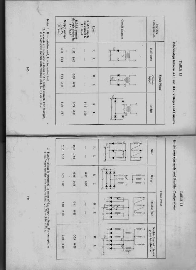
This might surprise you, but with three phases, and a six diode bridge, the RMS current through your slip rings will be 82% of the total final dc current.
Cheers, �Tony.
brucedownunder2 Guru Joined: 14/09/2005 Location: AustraliaPosts: 1548
Posted: 05:55am 02 Jun 2018
Copy link to clipboard
Print this post
Barkly , I've been thinking ,how does a stepping motor work ? Could it be configured for your application ?
I have one small one out of a very large printer machine ,that has several wires that ,if I'm correct were used to rotate the motor in steps. A bit blurry in my pickled brain at this late stage in life,but ,maybe, it could be the answer ?.
I',ll find it in a day or so and take a photo of it .About the size of a coffee mug . Don,t remember it's voltage . Thats another question for you .How you going to get this external voltage up to your mill head ??. (Maybe a battery and a small inverter up there?.),hey, and a small solar panel ? Motorcycle battery?
Bugger, now I'm won,t be able to sleep for a few nights,I'm hooked again!.
Bruce
Bushboy
BarkyJ Senior Member Joined: 26/04/2018 Location: New ZealandPosts: 114
Posted: 06:16am 02 Jun 2018
Copy link to clipboard
Print this post
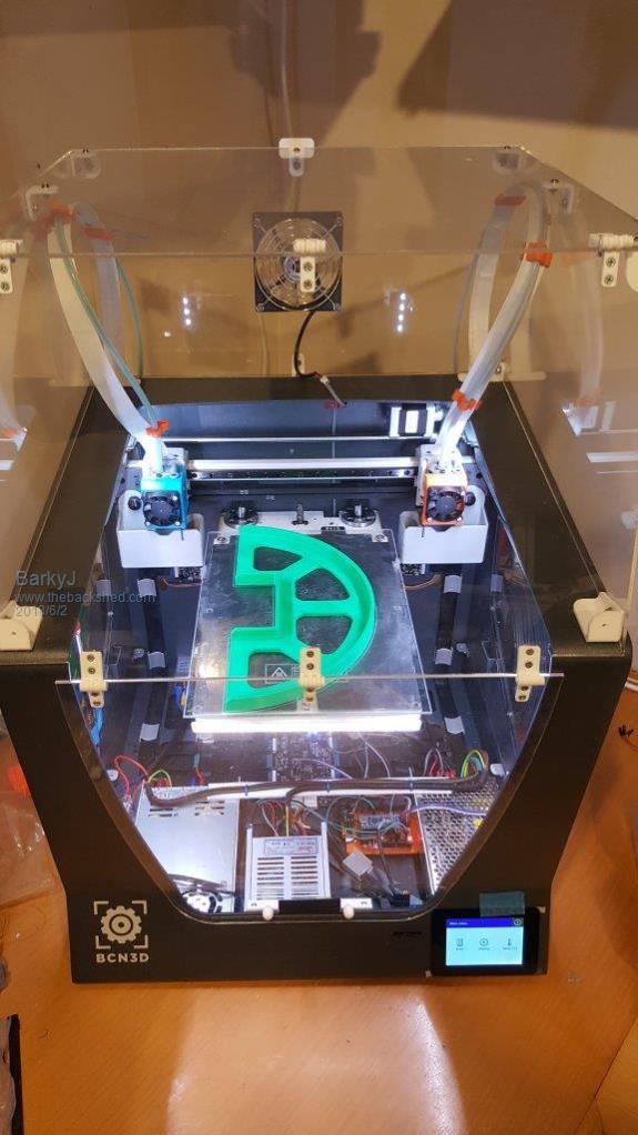
Hi Bruce Ha - the green thing is 1 of 4 of the things I have 3D Printed to act as an outer cover holder for the generator, just to keep out most of the weather from the inside. So the glass plate goes inside the 3D Printer, and it then prints plastic in the design you load in.
Here is a pic of my 3D printer, pretty heavily modified from stock. Working pretty great really. Good for making prototypes of things, or in this case, good for making bearing holders and brackets and stuff.
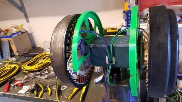
Got distracted doing a few other bits today, but got some of the wiring done, just temp until the slip rings arrive, and till its all proven to be OK, then ill strip it all down and paint the steel etc.
Can see 3 of the 4 of those holders in place, the last one just finished on the printer, in the first picture.
BarkyJ Senior Member Joined: 26/04/2018 Location: New ZealandPosts: 114
Posted: 06:25am 02 Jun 2018
Copy link to clipboard
Print this post
A stepper motor could work yes, but it would need quite a bit of drive I would imagine, to turn the turret when it has a wind going at it, etc. I have 2 DC geared motors I have currently in my sons go-kart I built him when he was 2, goes about walking speed and has incredible talk.
Sounds like you have a nice stepper there though, I have smaller NEMA ones here, about 50mm cube or so, and they would not do at all. Coffee cup size would have more go though.
You need a stepper driver for them, you dont just apply power to make them spin.
So I have the 6 phases come down the pole from the turret. And I will then need external power as you say, coming from the group up to the motor to drive the turret, but not going into the turret. I likely will just have a hole in the side of the main pole, maybe with a welded ring to reinforce it (maybe), and then have the wires to drive the motor coming out of that. Still to be determined.
The aim is to have a small solar panel I have, keeping a 12V battery topped up, which drives the control system, and this motor, but I dont think the one I have will be large enough, but we shall see. I might also tap a little bit of juice off the windmill and charge the battery with it, via a little transformer or something. Again still to be determined. It will be powered somehow :) Heck, even an AC-DC plug pack. Will figure that out, lots of options.
brucedownunder2 Guru Joined: 14/09/2005 Location: AustraliaPosts: 1548
Posted: 06:57am 02 Jun 2018
Copy link to clipboard
Print this post
thanks BarkyJ, now you have got me --question time ??
This printer thingo --could you give me and a few of the other challenged blokes and shielas on here how it works --like ya just don,t run down to office works and get a load of paper and a few color thingos ,surely?
mine, if I'm real lucky --paper in one end , out the other a pic of a pretty girl -well you know ,what I mean???
your gismo is a wee bit different ,i'd reckon???
take us though how ya get a green plastic thingo out of a piece of paper ,please.
dumbskull BruceBushboy
Madness Guru Joined: 08/10/2011 Location: AustraliaPosts: 2498
Posted: 07:19am 02 Jun 2018
Copy link to clipboard
Print this post
Bruce 3D printers are pretty much like your Office Works scenario but instead of buying ink and paper you buy spools of plastic filament. Aldi have had 3D printers a few times now.
They work with a print head that is a heated nozzle and motor that drives the filament into the head force molten plastic out the nozzle. The printer puts down one layer of the object on the glass bed then raises the head a touch and puts down the next layer.
Jet engine manufacturers are using 3d printing to make prototype blades for jet engines with 3d metal printer. There are also 3d printers that print sand moulds for casting metal and 3D printers that use concrete to print buildings.There are only 10 types of people in the world: those who understand binary, and those who don't.
BarkyJ Senior Member Joined: 26/04/2018 Location: New ZealandPosts: 114
Posted: 07:29am 02 Jun 2018
Copy link to clipboard
Print this post
Yep, as Madness said.
Prints layer by layer, starting from the glass all the way up to the top of the model. They come in various forms, but the concept is the same.
I got my first 3D printer about 9 years ago now, it was small and could print things about 120x120x120 or so in size, max. This printer I have now can print 210x297x210, it has dual heads so you can do 2 colours easily on a print, or 2 different materials.
Very handy things to have.
brucedownunder2 Guru Joined: 14/09/2005 Location: AustraliaPosts: 1548
Posted: 09:18am 02 Jun 2018
Copy link to clipboard
Print this post
Thank you Madness and Barkly,.
Explains it perfectly,I though I saw it explained on the tv ,but now I,m ok.
Amazing what you are doing ,watch every day . I used to do all this other ,not so modern stuff ,but slowed down now ,so just enjoy you guys building stuff.
Thank you very much ,
Bruce Bushboy
yahoo2 Guru Joined: 05/04/2011 Location: AustraliaPosts: 1166
Posted: 11:56am 02 Jun 2018
Copy link to clipboard
Print this post
I was kinda hoping that you would restrict the turret movement to maybe 460 degrees and let the cables twist for a good length down inside the pole. No slip rings! Seeing as you are going the road less traveled and bucking convention. I guess there would have to be a sensor or a switch to send the turbine 270 degrees in the opposite direction when it hit the end point.
I just looked at the wind direction graph on my weather station, it has done 10 anticlockwise rotations, looking from the top down in 3 months. I almost never get a NE wind so that is where I would put an overlap. The highest I have seen since August is 8 laps in a month, only one rotation clockwise in the last 10 months.
I have fitted a lot of trackers to satellite dishes in the past. Sometimes I used gear or worm drive rotary actuators, some were 36 volt or 24 volt some had limit switches and a reed switch pulse counter others had an encoder.
It would be possible to cut down a solar tracker linear actuator (I know some have fully adjustable limit switches) and fit a sprocket for a chain or cogged belt drive. I'm confused, no wait... maybe I'm not...
BarkyJ Senior Member Joined: 26/04/2018 Location: New ZealandPosts: 114
Posted: 12:19pm 02 Jun 2018
Copy link to clipboard
Print this post
Limiting turrent movement didnt really float my boat, if I am honest. Slip rings just seemed easier, especially now that I am dealing with smaller current. Just seems like the 'right' thing to do, so I have gone that way.
May very well just get back and forth winds and never do a full rotation - time will tell, but at least this covers all bases.
Interested to hear more about these solar tracker actuators. Do you have any info on where to buy, so I can have a look at them etc? URL or something?
The motor I have in mind at the moment is a 350W 1:9.778 ratio gearbox on it, so the motor spins at about 3000RPM, and the output shaft does about 306RPM. It has a little 9 tooth bike chain sort of sprocket on it, so couple that with a larger tooth sprocket on the base of the turret and have the pole go up inside that, then it should make for a decently slow speed.
I did ideally want a cogged drive belt rather than a chain, but not sure if the shank on the motor is long enough to take off the chain cog and put a belt drive pulley on it, but I haven't looked at it for a few years, so it might be possible to do that. Otherwise a well greased chain with a cover im sure would also be OK.
I have 2 of them driving the back wheels independently of a wooden based cart I made my son, about 5 years ago. It has 2x 12V high capacity gel batteries under the frame, and 2 e-bike motor controllers. Works really well, but his knees are now near his ears, so time to re-purpose it. Its also a bit slow for him too. Using the batteries for this too would also be a bonus.
DaveP68 Senior Member Joined: 25/11/2014 Location: New ZealandPosts: 292
Posted: 09:36pm 02 Jun 2018
Copy link to clipboard
Print this post
This might surprise you, but my three phases real world readings were done on an actual stator wired 1x12C Delta.
I measured 2.05 Amps AC (True RMS meter) inline between Phase A out of stator into and Phase A input into the rectifier. This will be the current flowing through the slip ring. The DC reading out of the Rectifier was 2.8 Amps.
That's close enough to the 1.4 times I stated before or in other words the AC current was 73 % of the rectifier DC output value for that test. As saturation is approached the reading changed to about 72 % on one test I did.
All this was done at a high power level of 550 W at around 500 RPM so there could have been a bot of imbalance in the circuit when reading were taken.
If these readings where take on a rectifier connected to the mains with high current potential then the 82 % figure should hold up.
Taking theoretical values into account is nice, but I prefer real world data as that will be more useful to James anyway. A 9 % difference is nothing anyway and all I wanted to point out is the 5 Amps rating on the slip rings is safe operating limit to have.
Most of the time the currents will be much lower as the wind is cyclic in nature. It follows the Pareto distribution law, look it up very interesting.Edited by DaveP68 2018-06-04There are realities if you do not accept, will lead to frustration because you will be spending time on wrong assumptions and the results cannot follow! The Dunning Kruger Effect :)
Madness Guru Joined: 08/10/2011 Location: AustraliaPosts: 2498
Posted: 09:41pm 02 Jun 2018
Copy link to clipboard
Print this post
I saw a video about one of the giant wind turbines that use motors to drive it to track the wind. They had cables hanging inside the tower and a computer controlling it so that it was limited to 3.5 turns either way. It would not be that difficult to do the same with an Arduino. Once it got near the limit of turns just rotate it back to home.
Another source of very robust motor and gearboxes is an Electric sliding gate opener, the one I have is supposed to be able to move at least a 1 ton gate. It would be very easy to fit a cogged belt in place of the gear, there is also already a sensor on the shaft to count pulses. With a small pulley on the motor and a large one on your turret it should be a walk in the park for it.There are only 10 types of people in the world: those who understand binary, and those who don't.
brucedownunder2 Guru Joined: 14/09/2005 Location: AustraliaPosts: 1548
Posted: 10:51pm 02 Jun 2018
Copy link to clipboard
Print this post
Good morning BarkyJ,
was thinking , have you thought about "down-wind" type of arrangement?.
The other type I remember is the "fold-back" type that goes horizontal in the strong gusts then settles to vertical to capture the wind strength . had a picture of one once ,will try and locate it.
that 3D printer is amazing ,imagine all the parts you could make ,mind boggles?.
Good luck with your project ,have a day off ,,take the kids fishin?,lol.
BruceBushboy
Warpspeed Guru Joined: 09/08/2007 Location: AustraliaPosts: 4406
Posted: 10:55pm 02 Jun 2018
Copy link to clipboard
Print this post
One crazy thought that comes to mind, is that if you are going to use a motor to turn the machine, why not rotate the whole mast as well ?
That could then place the slewing motor, slip rings and azimuth sensing all at ground level.
Less weight up there, and much better access for many of the parts.
The mast itself would need to be made pretty stiff in torsion. It should not be too difficult to mount bearings at the guy positions.Cheers, �Tony.
Warpspeed Guru Joined: 09/08/2007 Location: AustraliaPosts: 4406
Posted: 11:24pm 02 Jun 2018
Copy link to clipboard
Print this post
Solar trackers have one supreme advantage, they only need to move very slowly. You are going to require something much more powerful that can shift the whole machine around faster than fifteen degrees per hour !
A dc motor should work fine, but if its a simple analog servo system, motor power consumption may be fairly continuous because it will always be trying to correct back and forth for any play or lost motion in the system. Any flutter in your wind direction vane is going to keep the system rather busy constantly correcting.
The basic concept is certainly sound and offers some interesting advantages. I think this is going to take quite a bit of development to get it exactly right, and mounting the working parts at ground level might turn out to be a major advantage.Edited by Warpspeed 2018-06-04Cheers, �Tony.
BarkyJ Senior Member Joined: 26/04/2018 Location: New ZealandPosts: 114
Posted: 11:36pm 02 Jun 2018
Copy link to clipboard
Print this post
Hi Bruce
Yeah I have looked at a few follower designs, but at this stage I have just opted for out right control, rather than anything self controlled. Call me crazy, but this is just the direction I am heading in at the moment. I have seen a few folding back furling systems, and then the normal fold to the side furling systems. Neither really appeal to me at this stage, but I may revert to one of them if this plan goes wonky.
The 3D printer is certainly great. The strength of the parts is not as good as if the parts were injection or rotational moulded etc, however it works good for what it is, and if you design the parts right then they can still be functional parts.
Day off doing some windmill and entertaining kids is the plan, yes. Want to get as much done physically this long weekend, before having to go back to work and things plaguing me and me not being able to action them :)
BarkyJ Senior Member Joined: 26/04/2018 Location: New ZealandPosts: 114
Posted: 11:45pm 02 Jun 2018
Copy link to clipboard
Print this post
Hi Warpspeed.
That is certainly a neat idea. The motor I have at the moment though is not heavy though. Having something at ground level would be nice though, but once its in place and protected from the rain etc, anything that needs adjustment would in theory just be control wise, rather than physical.
The ID of the turrets vertical tube, is about 77.5mm and about 6mm wall, and when I got this steel I looked in the book and the next tube down has an OD just under this. So with a little dressing, they should run on each other nicely. At this stage the idea is to cut a disc of teflon or another hard plastic, and just put it on the inside end of the turrets tube, and the pole will just run on that, rather than being metal on metal.
The plan is to get a 6m length of the mast's steel, and cut it in half an implement a hinge like many of you guys have done before, so I can fold it down to service it on the ground. But those details are still a Work In Progress.
Rotating the whole mast is a very interesting idea though, but would make for large bearing at the bottom, and a somewhat challenging task to stablise the mast too, unless there were the tether points up high running on a bearing of their own. hmm. ill give this some more thought - thank you.
BarkyJ Senior Member Joined: 26/04/2018 Location: New ZealandPosts: 114
Posted: 11:47pm 02 Jun 2018
Copy link to clipboard
Print this post
Yeah I certainly dont plan on running the motor constantly, making fine adjustments. I likely will take the average of the wind vane, and then make adjustments periodically, possibly more so at lower RPM and less so at higher RPM. But I still need to figure out that detail - but end of the day its just software. It however will not be 1:1 wind vane to motor output thats for sure.
Cheers
brucedownunder2 Guru Joined: 14/09/2005 Location: AustraliaPosts: 1548
Posted: 11:56pm 02 Jun 2018
Copy link to clipboard
Print this post
Yes, tube in tube is what I have used with success.
I did it this way ,the both tubes were about 3mm in difference internally and the other externally . So I got some plastic waste water pipe ,the stuff they use under your sink ,Etc. split it lengthways with a hacksaw,(one side only) ,then spring it open to fit the smaller pipe and set it securely with a couple of countersunk set screws.. Grease it well and it worked perfectly .