Notice. New forum software under development. It's going to miss a few functions and look a bit ugly for a while, but I'm working on it full time now as the old forum was too unstable. Couple days, all good. If you notice any issues, please contact me.
DaveP68 Senior Member Joined: 25/11/2014 Location: New ZealandPosts: 292
Posted: 07:45am 15 Jun 2018
Copy link to clipboard
Print this post
Can anyone shed light on blade weight to help out James?
Most of what I've posted over the last 2 days mostly reflates to this important fact.
A "personal win" for me if we want to focus on these (not my intention) is how accurate my guess of 5 kg's was for the blade weight, as it ending up being 4.5 kg's.
At a current "per blade" weight of 4.5 kg's the Centrifugal force acting on the hub will be 1887 kg's at 500 RPM. That's A LOT of force!!
If the blades go into runaway and they reach 750 RPM that force "per blade" goes up to 4250 kg's!! At 1000 RPM it climes to a whopping 7550 kg's and that's "PER BLADE"!!
Blot them down carefully, as a blade coming off has the potential to travel some distance before it comes to a sudden stop! Heaven forbid through the windscreen of unsuspecting car travelling nearby...
My intention here is not to scare James at all as I'm right behind him. Everyone to date has made equally valued contributions.
Just hoping someone out there can give some advice on this one as I could be over thinking this one and James will be fine with what he's put together so far.There are realities if you do not accept, will lead to frustration because you will be spending time on wrong assumptions and the results cannot follow! The Dunning Kruger Effect :)
BarkyJ Senior Member Joined: 26/04/2018 Location: New ZealandPosts: 114
Posted: 09:05am 15 Jun 2018
Copy link to clipboard
Print this post
Yep those are certainly scary numbers.
500RPM already scares me a bit, so I likely won't let it get even that speed, to start with at least. I will just turn it out of the wind earlier with my turret control. But yes, if that fails for whatever reason and things go pear-shaped, it's certainly something to be well aware of and figure out what to do about.
Each blade is bolted with 3 bolts in a triangle pattern, to the main steel hub, as well as having steel runners going out 400mm or so, so there are 7 bolts in total. At this stage they are 8mm, is what the plan is for.
I do need to think of a backup plan if the motor fails and what to do to get the windmill out of the wind and disabled, in case of an emergency.
The plan though is to turn it out of the wind as the speed increases, so I can then run it at say 20 degrees or 45 degrees etc to the wind, as I see fit, or 90 degrees if required. Leaving it up to the mercy of self direction by tail/wind does scare me, but at the same time relying on mechanical also is also somewhat scary. I have more thinking to do, but I am still going with a motor driven turret, and no tail.
At least so far.
Madness Guru Joined: 08/10/2011 Location: AustraliaPosts: 2498
Posted: 11:34am 15 Jun 2018
Copy link to clipboard
Print this post
Are you calculating the centrifugal force at the tip? It will much less as you get closer to the centre.There are only 10 types of people in the world: those who understand binary, and those who don't.
yahoo2 Guru Joined: 05/04/2011 Location: AustraliaPosts: 1166
Posted: 12:20pm 15 Jun 2018
Copy link to clipboard
Print this post
I think it is more likely to flutter and flex the blade close to the root above the clamp plates which could form a crack.
If the turbine will hold with the phases shorted it should be fine.
the general direction of the wind doesn't change much, it should be quite easy to park it out of the wind.
my rough calculations at 70 m/s (250 kph and 445 rpm) tip speed on a 3 m diameter fan spreading the 4.5 kg evenly gives me 7300 newtons per blade (740 Kg roughly) I could well be wrong, its been a while since I had to do any of this stuff. I'm confused, no wait... maybe I'm not...
DaveP68 Senior Member Joined: 25/11/2014 Location: New ZealandPosts: 292
Posted: 10:16pm 15 Jun 2018
Copy link to clipboard
Print this post
Yes Yahoo2's numbers are closer to the mark as missed some minor details, it's still 1000 kg's of blade force at 500 RPM! That's a lot of force in the grander scheme of things...
As I stated before profiling the Airfoil shape of the blades trailing edge more on the outer half section will get the weight down in the region that matters most.
The inner half of the blades can still have plenty of meat on them to maintain strength.There are realities if you do not accept, will lead to frustration because you will be spending time on wrong assumptions and the results cannot follow! The Dunning Kruger Effect :)
BarkyJ Senior Member Joined: 26/04/2018 Location: New ZealandPosts: 114
Posted: 09:57am 24 Jun 2018
Copy link to clipboard
Print this post
Evening All
Bit of an update. I have been pretty busy with work lately so not as far forward as I would like, but such is life.
I think I have the blades to an OK point to start playing with them now. They are all basically the same weight and shape, and once I mount them on the hub I will balance them to get them OK relative to each other and the mounting. This should happen in the next week or so.
Got the plate cut for the blades to bolt to, and the arms which bolt behind the blades, along with the thinner arms which bolt to the front on the blades. These arms all both to the central plate too, sandwiching the blades and go up about 400mm from the centre up each blade.
I got ring cut which will be welded to the bottom of the turrets pipe, which will have a 32T cog bolted to it. On the main pole, the motor will bolt to this, for rotating the turret, linked with a chain on the cogs. On the cog are 2 geartooth sensors, to allow quadrature like data to come off the teeth as the motor turns, to let me track exact position and direction of turn of the turret. Cables for the motor and sensors will enter the main pole, and run down to the controller along with the 2x 3 phase cables from the dual stators.
The geartooth sensors will track the position of the turret using the teeth on the cog, so my controller should always know where it is pointing, within a few degrees. If for some reason the turret moves without being driven (such as if the wind overpowers the motor brake - which hopefully won't happen), then the controller will still know where it is, and move it back accordingly. Still to implement all this stuff, but this is the idea. I am still toying with the idea of also putting up an electronic compass, so I can know where North is etc.
There will be 3 wires running up the pole into the turret which will connect to the RPS sensor also. I might run 4, so I can have a 2nd RPS sensor reading coming down too, so I can attempt to alarm if one of the sensors fails etc.
I hope to get the main pole in the next week, will get a 6m length, 1m will go into the ground into a formed hole in a slab of concrete, then 2.5m above the ground there will be a hinge for lowering the top half down to ground level. Then the top 2.5m will be above that obviously, with the turret on it. Just below blade level, I will put in some eyelets for the supporting cables, which will go out to support the whole thing. I will figure something out for raising it up again, like a smaller pole welded to the outside of the top section, so its possible to pull the top up vertical from the ground. Nothing new here.
I designed a PCB and got my first 'production version' of my controller built. I am using a 32bit 120Mhz controller now, well overkill, but will give me plenty of options and allow it to drive all the gear I have in my head for the future. Still testing the hardware, but so far so good.
I have a wind position sensor and wind direction sensor on its way, they should be here this week, which talk to the controller over RS485 comms. These will be mounted nearby and provide data to the controller as to the wind direction and speed, and allow my controller to position the turret using the motor system, into the wind, or at X degrees to the wind, or out of the wind when really windy, etc etc.
Being able to control the turret will also allow me to park it to allow it to be in the right position for lowering the windmill using the hinged pole, so the blades are in a favourable position.
I still have some thinking to do for 'what if' situations, but those will come in time.
I was just driving up the main road towards my house, which you can see partially from the main road, and just realised the place I am going to be putting the windmill is very visible from the main road. Just curious about regulation requirements here in New Zealand - does anyone know. Do you need to do something to get approval, or do you just go for it? This is not going into the grid, its an isolated system.
Cheers
Warpspeed Guru Joined: 09/08/2007 Location: AustraliaPosts: 4406
Posted: 10:15am 24 Jun 2018
Copy link to clipboard
Print this post
The idea of an electronic compass had crossed my mind, but all those spinning magnets up there might confuse it a bit. But it might still work well enough to be useful.
An incremental encoder can certainly get lost due to any power outage, so it probably does need some automatic self correcting mechanism. The usual way is to have a third sensor that just resets the incremental position counter to some known specific reference direction. Could be due north, but it really does not matter.
If it gets lost, as soon as the third sensor produces a pulse, which it will do eventually, it resets everything to that exact known direction and its then corrected. Cheers, ĀTony.
BarkyJ Senior Member Joined: 26/04/2018 Location: New ZealandPosts: 114
Posted: 05:13am 26 Jun 2018
Copy link to clipboard
Print this post
Yep, had thought of another sensor to reset everything, but it could be days for that to happen depending on the wind, so that is where the idea of the compass came in.
Noise is a factor for that which I have considered also. However, if noise is an issue then I could time samples to happen when there is no/low wind, and reset things then.
Anyway, there will be something to reset the quadrature to a known location, yep.
I may even get it to home periodically, say once a day, when wind is low. Dunno. Lots of possibilities.
The controller and motor etc will be on a 24V battery arrangement, and I have 20W of solar which will be keeping that charged. Ill monitor how that goes over the first few days and just ensure the solar is more than enough to keep it topped up, so hopefully power outages will be few and far between. With the motor only doing small movements say once a minute, and it will only be on for < 5 seconds I would imagine, the power draw should not be that high at all. Motors will be PWM'ed to adjust the speed, so I will be able to tune in the appropriate speed to move the turret.
Cheers
Warpspeed Guru Joined: 09/08/2007 Location: AustraliaPosts: 4406
Posted: 05:35am 26 Jun 2018
Copy link to clipboard
Print this post
If the home position coincides with the usual prevailing wind direction, the reset action should get a reasonably good workout.Cheers, ĀTony.
Warpspeed Guru Joined: 09/08/2007 Location: AustraliaPosts: 4406
Posted: 01:08am 27 Jun 2018
Copy link to clipboard
Print this post
Another thought about the loss or corruption of the direction sensing.
You can get good quality potentiometers that are designed for continuous motion (without rapidly wearing out) and are often used for position indicating with mechanical servo systems. These potentiometers are also designed to have no mechanical end stops.
There would be all kinds of difficulties using one of these for primary position indication, because of the necessary break in the track at one point, and the sudden very violent 360 degree jump in readout that creates.
But it could be used for verifying the primary incremental counter at any time, and you could write into software to just ignore it whenever it gets dangerously close to either end of its resistive track, and only carry out a correction when its in a safe area of its angular travel.Cheers, ĀTony.
Madness Guru Joined: 08/10/2011 Location: AustraliaPosts: 2498
Posted: 02:00am 27 Jun 2018
Copy link to clipboard
Print this post
You could make a version of a rotary encoder with 2 micro switches and 2 semicircle pieces of pipe offset by 90 degrees. This would allow a microcontroller to know the direction and number of turns from home position.There are only 10 types of people in the world: those who understand binary, and those who don't.
Tinker Guru Joined: 07/11/2007 Location: AustraliaPosts: 1904
Posted: 09:17am 27 Jun 2018
Copy link to clipboard
Print this post
I have used one of these servo pots for many years on my windvane (direction indication). A cascaded LM3914 chip decoded the varying voltage output to 16 direction steps, driving LED's arranged in a circle. I had set the 0 pint to the least common wind direction here - North.
Unfortunately the pot track wears out after 10 years or so at the most common wind direction, SW here.
There is an optical rotary encoder (I have one but not yet installed) which puts out two pulse trains offset by 90 degrees (if I recall correctly) and from that the direction could be computed. However, this would require more than the two existing wires going up to my windvane which is why it has not yet replaced the worn out servo pot. Klaus
Boppa Guru Joined: 08/11/2016 Location: AustraliaPosts: 814
Posted: 12:08am 28 Jun 2018
Copy link to clipboard
Print this post
I had an old exmil setup for many years that had two loops, one driven by a circuit, the other hooked up to a meter, depending on the mast rotation, it varies the output on the meter (variably coupled transformer) was great until I moved and lost the box it was in :-(
BarkyJ Senior Member Joined: 26/04/2018 Location: New ZealandPosts: 114
Posted: 09:21am 15 Jul 2018
Copy link to clipboard
Print this post
Hey All
Bit of an update.
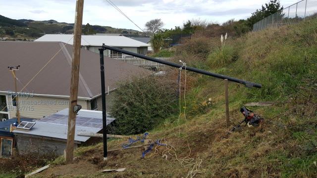
Got the mast pole, cut it in half, added a hinge arrangement and a lock. Fabricated the motor mount, and the mount for the drive cog.
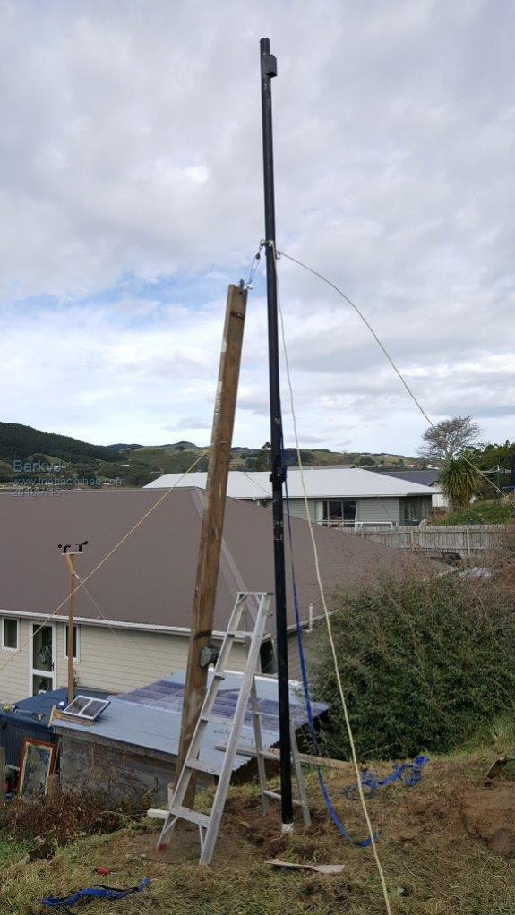
Over the weekend we got the mast pole base concreted, pole is removable, hinged 2.5m above the ground, and then about 3.2m above the hinge. Pole goes into the ground just under a meter. It's a 76mm OD medium wall black pipe, about 3.6mm thick or so. Got the guy wire supports in the ground. Installed the 3 12mm eyelets into the pole for the guy wires. Devised the winch system to raise and lower the mast today, that works well. Measured all the lengths for the wire rope for the supports after getting the mast fully raised up, so will get those bits ordered tomorrow. Will be using 6mm galv wire rope, turnbuckles, wire gips, etc. Should work out well.
All going pretty well really.
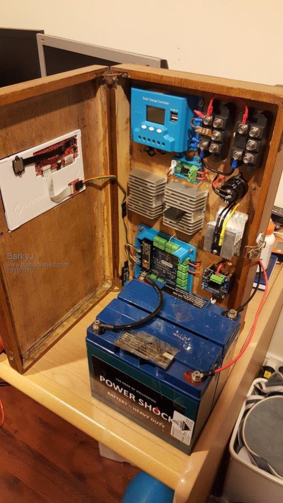
Been building the more final controller, which is taking shape, few more bits to add to it plus more testing to do, more code to write, but going well.
Got the wind vein and speed sensor installed on top of the control shed, a stone throw from the windmill itself, along with 20W of solar to keep the controller's batteries charged during the day.
Few progress pictures.
Next step is to get the blades I have made, mounted on the hub, balanced, then bolted to the generator. Then the generator connected to the controller for some more testing, then attached to the mast, motor mounted, more testing, etc etc, then we might be somewhere near ready to do some initial controlled tests. Still got a few 'what if' situations to work through and how to handle them, but they are all part of the fun of building one of these things.
Enjoying every minute of it, what a great project.
Cheers
Boppa Guru Joined: 08/11/2016 Location: AustraliaPosts: 814
Posted: 09:32am 15 Jul 2018
Copy link to clipboard
Print this post
Only issue I can see that might cause problems is having the sensors on the shed- you have a bit of a hill behind you by the look and surrounding houses etc, the wind at the shed level might not be anything like the wind at the genny- I would think having the sensors near the top of the mast might be less of an issue Been ages since I played with wind gennys, but anything nearby (trees/houses/hills etc) can cause turbulent air flow around them
I know a genny system on a yacht to provide power when moored, they had one at the top of the mast, one at the bow and one at the stern, all three often ran at different speeds and different directions- sometimes facing opposite each other- all this with a length of 45 ft between them max and a height difference of about 80ft...
BarkyJ Senior Member Joined: 26/04/2018 Location: New ZealandPosts: 114
Posted: 09:10pm 15 Jul 2018
Copy link to clipboard
Print this post
Hey Boppa
Yep, a valid concern. Only had it up a few days, and the wind direction does seem stable as either a Westerly or an Easterly, but the wind has been so light. It doesn't flutter around much at all, so I think we are OK.
On the top of the hill behind us is a school field, and the wind often comes off the field and then down past us, as it flows down to the road below. The windmill itself should cop all this as its basically level with the field, but yes its a question as to whether the sensors will pick this up accurately, or show something different.
So far it seems to be OK though, but its something I am monitoring to make sure its valid data.
I did think of putting sensors on the mast, but I didn't want the windmill itself to affect the sensors, so opted for close by instead.
BarkyJ Senior Member Joined: 26/04/2018 Location: New ZealandPosts: 114
Posted: 06:42am 18 Jul 2018
Copy link to clipboard
Print this post
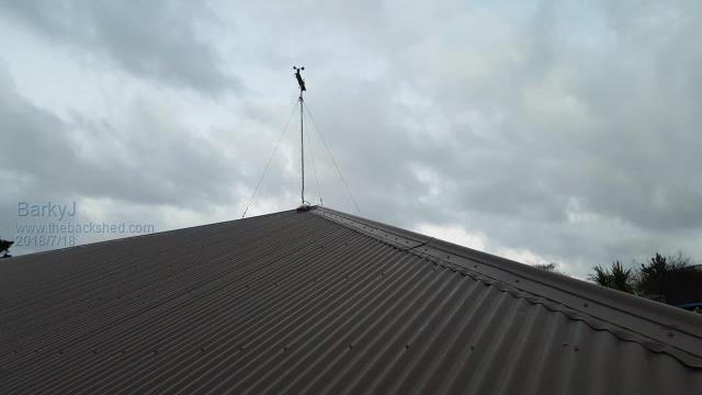
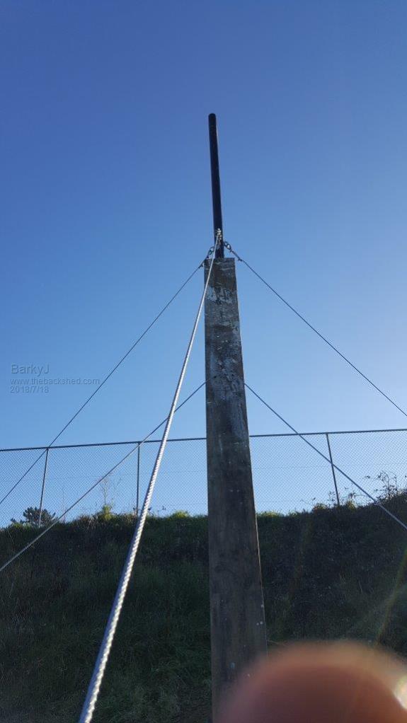
Boppa - you were quite correct, the shed turned out to be a flop in terms of location for the sensors. So today I rebuilt the mast and put it up on the house roof, which clears the hill now. And now I have a northerly and its nice and stable. Got it up just before dark.
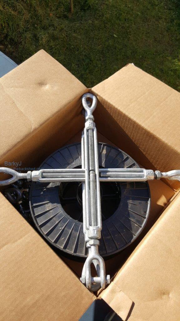
Got a box of presents today too, so got those installed (I should have been working...), but now the windmill is secured with 6mm steel cables.
Lifting plank is still in the pictures, that will be lowered down and removed obviously.
Pictures likely come out too small on the forum, hopefully they are still visible.
Making progress :)
BarkyJ Senior Member Joined: 26/04/2018 Location: New ZealandPosts: 114
Posted: 06:45am 18 Jul 2018
Copy link to clipboard
Print this post
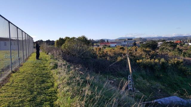
So the hill where Dad is standing in the last picture is about level with the rope eyes securing the mast. So there is about 1.6m above those to the top of the pole, so 100mm or so to the centre of the blades, and then 1.4m to the top of the tip of the blades. So it should work out well. Quite a difference in air when standing up on the hill, compared to down by the shed.
Time now to focus on the Turret again, get that rebuilt after painting it, get it installed with the motor, and then onto the blades.... gulp.
Warpspeed Guru Joined: 09/08/2007 Location: AustraliaPosts: 4406
Posted: 07:02am 18 Jul 2018
Copy link to clipboard
Print this post
Its certainly a fairly difficult site, but it may not be all that bad. The wind coming over from the sports ground may be a bit turbulent, but if there is enough wind, it should work fine. In the other direction, steeply rising ground is actually quite good.
I have never built a wind turbine system myself, and live in the yuppie suburbs so never will. But a long time ago I worked for the Victorian Solar Energy Council, and was part of the team responsible for planning and monitoring some government funded wind turbine sites, so this project is of great interest.
Boppa is spot on about monitoring at a position as nearly identical to the final turbine position as possibleEdited by Warpspeed 2018-07-19Cheers, ĀTony.
Madness Guru Joined: 08/10/2011 Location: AustraliaPosts: 2498
Posted: 07:22am 18 Jul 2018
Copy link to clipboard
Print this post
Turbulence will cause you lots of grief and the harder the wind blows the more turbulent it will be.
I struggled for a few years with a 1500W Dunlite up a 24 metre tower, strong turbulent wind would cause it to turn 360 degrees quite often. AFAIK you need to get at least 10 metres above anything nearby. I had a steep slope to the east and the blowing up it amongst trees was the worst even though the generator was at least 15M above them in altitude. A paper streamer on the end of a very long pole is one way to check turbulence. There are only 10 types of people in the world: those who understand binary, and those who don't.