
|
|
Forum Index : Microcontroller and PC projects : sensing 220vac
| Author | Message | ||||
drkl Senior Member Joined: 18/10/2015 Location: HungaryPosts: 102 |
Hello, What is the simplest method for sensing 220vac by micromite? drk |
||||
Chopperp Guru Joined: 03/01/2018 Location: AustraliaPosts: 1126 |
Hi, The safest way is with a 220V to low volts transformer then rectifying & filtering the output. The resulting output would need to be <3.3V for the maximum expected input. ChopperP |
||||
TassyJim Guru Joined: 07/08/2011 Location: AustraliaPosts: 6538 |
What do you want to do? Sence that AC is present? Or record the RMS voltage? Or do you want to record the AC waveform? for the latter, see this discussion from a few years ago https://www.thebackshed.com/forum/forum_posts.asp?TID=7158&KW=disturbance+recorder If you are looking at reading the RMS, rectify the transformer secondary at a relatively high voltage then use a resistor divider to bring it down to 3.3V range. That way the voltage drops in the rectifier diodes is less of a problem and save going for a precision rectifier circuit. Jim VK7JH MMedit |
||||
| CaptainBoing Guru Joined: 07/09/2016 Location: United KingdomPosts: 2171 |
nah, safest way is an opto coupler. Two of them with the diodes in reverse parallel between L & N and the transistors in parallel. Not much info but if you just want to know it's there, two checks 10mS apart - either one being true shows you have something above 2V on the mains. Three components: 180K 1/2W resistor in series with the diodes (slightly under wattage but as it isn't a constant flow it'll be fine), a two-pack opto and then a 10K pull up to VCC for the trannies working in common emitter. Active LO output on the collectors, straight into you sense input. Failing that just stick your finger on it - if it gets heavy really quickly and you want to drop it, it's live - JOKE! DO NOT STICK YOUR FINGER ON IT!  |
||||
| Paul_L Guru Joined: 03/03/2016 Location: United StatesPosts: 769 |
Two ways of sensing 220vac simply occur to me. One is to plug a small regulated wall wart power supply into the mains voltage and check for its DC output voltage. It will provide enough capacitive filtering to bridge many cycles of the line frequency, however it will also maintain its output voltage for a short period after a mains shutdown. An alternate would be to use the $0.85 US ON Semi/Fairchild 512 logic output optocoupler with schmitt trigger in a 6 pin dip but you will have to mount it on a PCB and fool around with a series current limiting resistor and monitor its output at multiple times during each cycle of the line frequency. https://www.fairchildsemi.com/datasheets/H1/H11L1M.pdf Paul in NY |
||||
CircuitGizmos Guru Joined: 08/09/2011 Location: United StatesPosts: 1427 |
On Ebay: 240V 220V AC Mains Sensor opto-isolator optoisolator optocoupler 5V 3.3V Arduino https://www.ebay.com/itm/240V-220V-AC-Mains-Sensor-opto-isolator-optoisolator-optocoupler-5V-3-3V-Arduino/272619019157?h ash=item3f795c1b95:m:myE43YEiZUq1yUTpsK0I5CQ Micromites and Maximites! - Beginning Maximite |
||||
| Chopperp Guru Joined: 03/01/2018 Location: AustraliaPosts: 1126 |
I still think the safest method for the hobbiest is using an AC plug pack / wall wart if you want to detect zero cross-over as I am currently doing or a DC unit as others have suggested particularly when experimenting. Optocouplers etc would be OK in a final product mounted in a proper enclosure. It's too easy to do do damage to yourself &/or equipment when playing with live mains. Connecting a Scope earth or your finger to the Active lead is a good example. An isolation mains transformer is essential for this sort of work. My 2c worth.  ChopperP |
||||
Quazee137 Guru Joined: 07/08/2016 Location: United StatesPosts: 603 |
Two parts I have had to used HCPL3700 and MID400 2018-06-11_062309_MAINS_DECT.zip 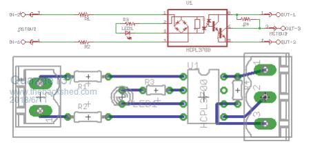 and cheap 3 phase detector 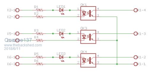 On a PLC interface we could not use wall wart so we use this 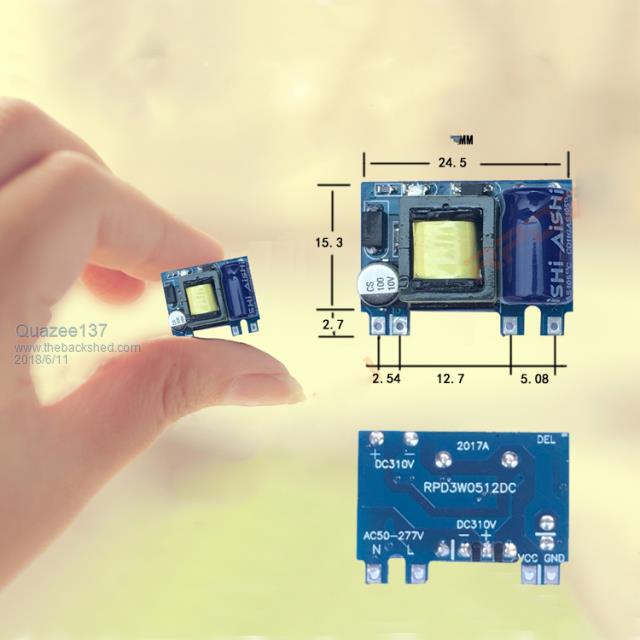 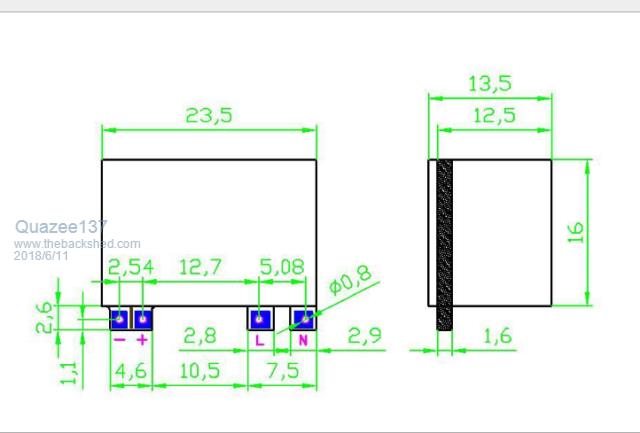 |
||||
| The Back Shed's forum code is written, and hosted, in Australia. | © JAQ Software 2026 |
