
|
|
Forum Index : Microcontroller and PC projects : Output driving two LEDs
| Page 1 of 2 |
|||||
| Author | Message | ||||
| LouisG Senior Member Joined: 19/03/2016 Location: AustraliaPosts: 130 |
Has anyone successfully used a Micromite output to drive a red LED in series with an optocoupler LED? I need to provide 32 isolated outputs to 24VDC field devices and would like to keep the parts count to a minimum. The setup will be an E100 driving red bargraph LEDs and TLP521 optocouplers. At first glance there might not be a sufficient voltage margin to allow driving the two LEDs in series reliably with the one series resistor. If this turns out not feasible I could move the LEDs over to the 24V side of the couplers and put them in series with the base resistors to the TIP107 PNP power Darlingtons, which perform high side switching of the loads. This would not be as convenient since the 24V supply would have to be switched on to view the LEDs when checking out the system. |
||||
| Geoffg Guru Joined: 06/06/2011 Location: AustraliaPosts: 3362 |
If you used open collector (should be called open drain) outputs pulling down from a 5V supply you might have enough to drive two LEDs in series (average 2V Vf each). Geoff Geoff Graham - http://geoffg.net |
||||
| LouisG Senior Member Joined: 19/03/2016 Location: AustraliaPosts: 130 |
That's true, Geoff. However, I would like to avoid reversed logic with open collector outputs for fail-safe reasons. When a Micromite output goes to zero I want to have the driven load de-energised. Open collector doesn't achieve this and adding automatic processor restart and other band-aids is not quite the same as having direct logic in the first place. I need to be conservative in this application. My 10 cents. It's an interesting subject. I wonder if it has ever been discussed on the forum? |
||||
goc30 Guru Joined: 12/04/2017 Location: FrancePosts: 435 |
Hi If you want max security, the best is to use relays. you have default fonctions (as no power) and you can also connect a watch-dog function, or manual switch. |
||||
| LouisG Senior Member Joined: 19/03/2016 Location: AustraliaPosts: 130 |
Thanks Goc. I regard relays highly. For a Micromite to operate one it would need a driver or amplifier of some sort. I don't seem to be able to get away from the use of electronic devices. I thought of a DIL relay driving a higher power relay but it seems there are no 3.3V relays for direct connection to the Micromite. There are 5V ones but then I would be back to open collector operation. Louis |
||||
| goc30 Guru Joined: 12/04/2017 Location: FrancePosts: 435 |
Hi louis you can use an ULN2803a. It is a Darlington transistor driver. It can output 500ma in 12v 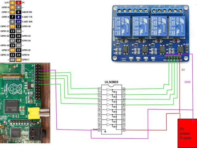 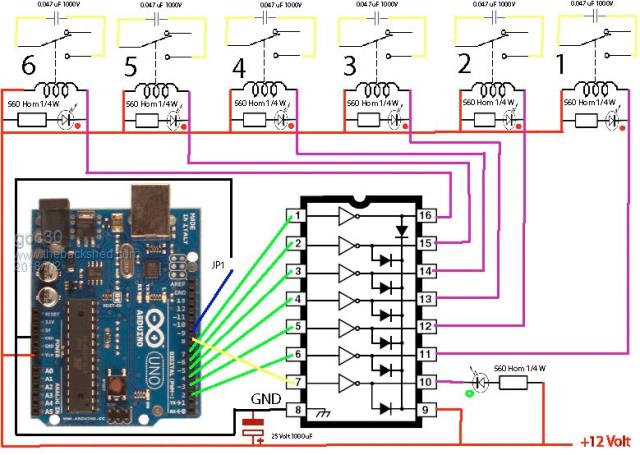 |
||||
Quazee137 Guru Joined: 07/08/2016 Location: United StatesPosts: 603 |
I am driving the quad relay boards from the 170 with no problems. Using pins 6,7,10,11 as a port. The only problem was the LM1117-MP5.0 was going into thermal shutdown "I was pulling 600mA" total. The fix was a 6 volt supply instead of the 12. 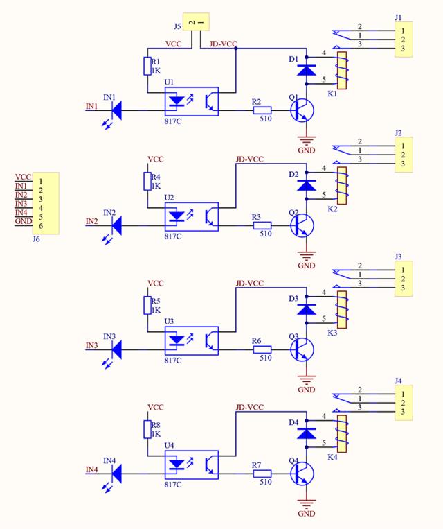 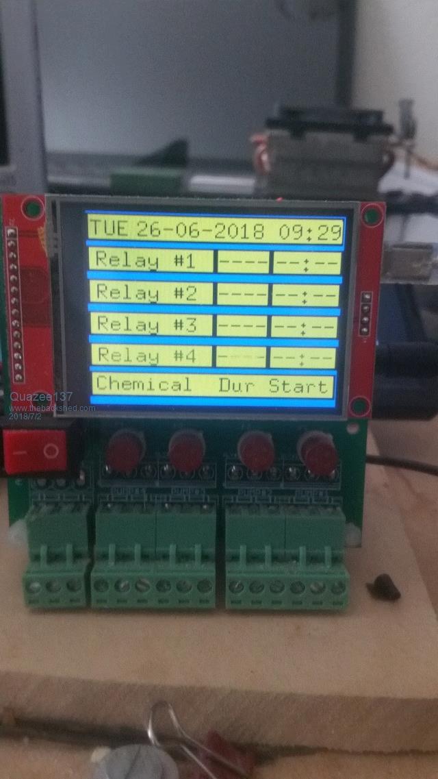 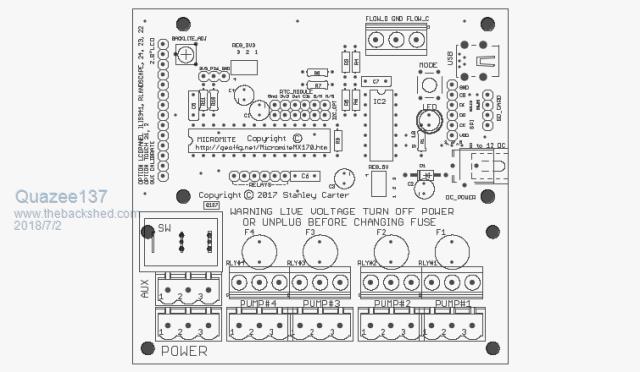 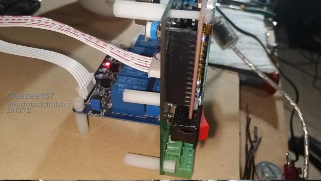 Just checked and it a bit over 2mA on the mites pins. You have 5v going to 1k and 2 leds. The relays need about 90mA each. |
||||
| erbp Senior Member Joined: 03/05/2016 Location: AustraliaPosts: 195 |
Why not run the opto-coupler LED and bar-graph LED in parallel. Not sure of the current requirement for the opto-coupler ones, but red bar graph LEDs are easily visible with only around 1mA current each, so each mite output pin should be able to handle that with ease. It adds one extra resistor to your component count for each channel being controlled, but resistors are cheap and if you use SMD's small as well. Phil. |
||||
| MicroBlocks Guru Joined: 12/05/2012 Location: ThailandPosts: 2209 |
You will also have to account for the max power in total that the chip can deliver. Two leds on a single port is not really a problem. But having 32 (64) of them will be. Even without the extra indicator the 32 leds from the optocouplers alone is to much because you have to take into account that they are all used at some time. If the optocoupler has a driver build in then you would be fine, but still no extra indicator led. Microblocks. Build with logic. |
||||
| LouisG Senior Member Joined: 19/03/2016 Location: AustraliaPosts: 130 |
Thanks for your suggestions guys. The system is for an experimental pilot plant so it has to be flexible. Am looking for a one-size-fits-all standard output to avoid specials and be able to accommodate changes. The largest 24VDC solenoid valve I have to switch is 13W. I want to standardize on high side switching (Grogster wanted it too). 13W is borderline for driving with a ULN2803. Would need an interposing relay. Could parallel its outputs but it's then non-standard. High side switching is needed to accommodate Schneider contactors, which are already wired and whose 24V coils are polarised, probably due to diodes/LEDs. Also, low-cost motorised ball valves from China have +/-24V permanently applied and require a +24V signal on a third wire to operate them. Need high side switching. There are other considerations but the final candidates for switching narrow down to relays or PNP Darlingtons. |
||||
| Volhout Guru Joined: 05/03/2018 Location: NetherlandsPosts: 5930 |
Dear LouisG, I have no idea how your high side switch circuit would look, but driving 2 LED's in parallel is technically possible from the micromite. The TLP521 you plan to use has specified behaviour over a wide temperature range, if diven from 0.5mA. On a 3.3V output of a micromite, that would mean a series resistor of 4.7k or 4.3k. If you use a similar current for your indicator LED that would limit the current per pin to a total of 1mA, perfectly fine, even if 32 are ON at the same time. Nowadays high efficiency LED's that give sufficient brightness at 1mA and below are easy to find. If they are available in LED BAR's I don't know. The LED bars are somthing a bit more 80's and 90's style, and then high efficiency LED's did not exist. For the optocouplers driven at 0.5mA, you have to accept that at higher temperatures they only output 0.1mA. So you driver (FET or BJT) has only 0.1mA GATE/BASE current. A darlington may not be sufficient .... especially not for the 13 watt valve. You would need an extra amplifier stage or use a FET). See attached graph. 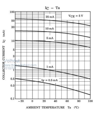 PicomiteVGA PETSCII ROBOTS |
||||
| LouisG Senior Member Joined: 19/03/2016 Location: AustraliaPosts: 130 |
Thank you Volhout for your input. I thought about Mosfets. I might have a fresh look at it. Louis |
||||
Grogster Admin Group Joined: 31/12/2012 Location: New ZealandPosts: 9975 |
My first thought is this: 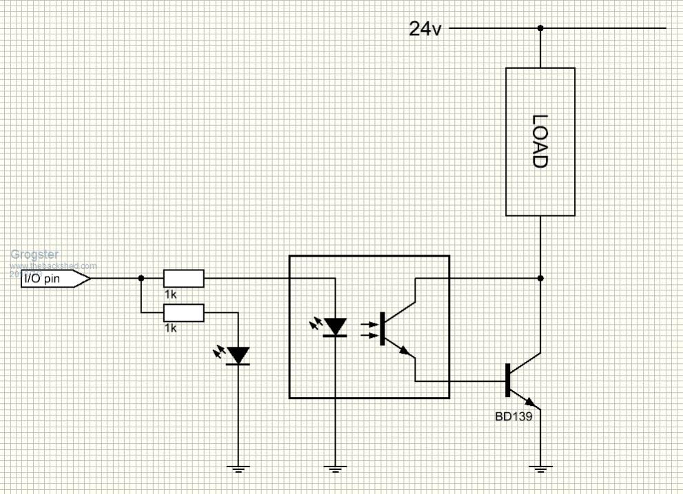 That's about as simple as you can get with bi-polars, but still allowing you to switch a reasonable current on each of the outputs, and have an LED for each one. The circuit could be simplified if you just had a MOSFET output, and you would not even really need the opto-coupler, as the gate of a MOSFET is totally isolated from the source-drain path anyway: 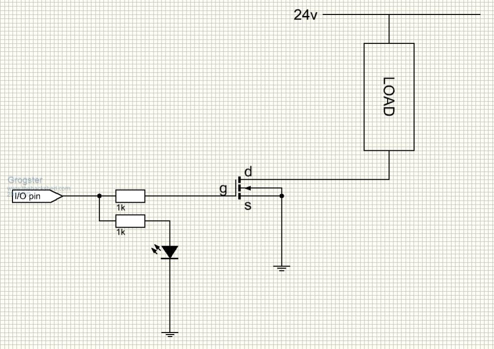 You just have to be a bit more careful when selecting the MOSFET to make sure it can handle the 24v and the load you want to put on it, and also that the Vgs(voltage between gate and source) is within spec. If all that jives, you are away laughing and no opto-coupler needed at all. But you still have your isolation, because the gate is isolated in a MOSFET, and there is no gate current to speak of unlike the base-emitter current in a bi-polar. Smoke makes things work. When the smoke gets out, it stops! |
||||
| Volhout Guru Joined: 05/03/2018 Location: NetherlandsPosts: 5930 |
Dear Grogster, Please understand that a high side switch is needed because the load he is driving is connected to ground. So both proposals need to be adapted to that. As for the optocoupler solution, you are drawing (assume 3.3V from micromite) 2mA for the optocoupler and 2 mA for the LED (1k resistors). That is 4 mA per pin. With 32 outputs that will be 128mA IO current only. Most likely this will work (max 200mA in Vss or Vdd pin). Over temperature you can drive roughly 0.8mA into the base of that BD139. If you would do high side drive, it would be a BD140 most likely. If the load is 13 watt at 24V, that is 550mA. At 550mA the current gain of the BD140 is 70. Meaning that you cazn switch (base current * current gain) = 0.8mA * 70 = 56mA. That is far below the 550mA needed. So a BD140 will not do it. You most likely need a darlington (as in the first post). As for the FET proposal: Yes a gate of a FET is isolated. But the maximum voltage between the gate and other pins of the FET is typically 20-30V.... And this voltage determins if the FET is ON or OFF. Meaning the isolation will conflit with the operation of the FET.. What I learned from this excersize is that we can drive the opto coupler harder than 0.5mA, giving us more power to drive the power switch. So the solution with a darlington may be feasible after all. A dalington has a gain of 800 or more (not 70), so with 0.8mA drive current from the opto coupler it would most likely switch fine at 13 watt load. In fact, you have your circuit ready..... PicomiteVGA PETSCII ROBOTS |
||||
| Quazee137 Guru Joined: 07/08/2016 Location: United StatesPosts: 603 |
It's not the opto you wanted but it may make things easier. 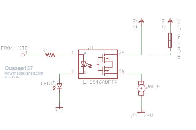 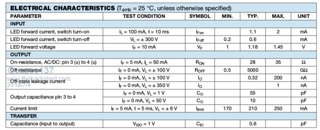 At mouser and digi-key LH1546ADFT 24@$31.92 25@$37.62 I have a few left over from a project and it works with the chip leds I use but I dont have the bar display to test. |
||||
| Volhout Guru Joined: 05/03/2018 Location: NetherlandsPosts: 5930 |
Dear Quazee137, Nice opto's. Would work very well for driving (small) relays from 24V. Tread starter however talked about 13 watt load. That is not for the faint of heart. 13 watt at 24V is 550mA or 44 ohm resistance. The opto couplers you mention have 28 ohm internal resistance (at 5mA drive, not 2mA). total resistance (load + switch) would total up to 44 + 28 = 72 ohm That would limit the current to 24V / 72ohm = 330mA Although that may be enough to drive the 13 watt load (marginal, but might "just" work), it means the opto coupler dissipates I2R = .333*.333*28 - 2.8 watt. Thermal meltdown.... But a good solution for smaller outputs (up to 100mA or so). Regards, Volhout PicomiteVGA PETSCII ROBOTS |
||||
| LouisG Senior Member Joined: 19/03/2016 Location: AustraliaPosts: 130 |
Thanks once again guys. @ Grogster: I really need high side switching. I recall that it was something you were pondering recently too. @ Volhout: Isolation of the gate is understood but I really need galvanic isolation. In Grogster's circuit the minus sides of the 3.3V and 24V supplies are commoned. @ Quazee137: The connection arrangement you've shown to the opto is for switching AC. The one for DC is slightly different. In any case I am familiar with the device. Thanks. Louis |
||||
| robert.rozee Guru Joined: 31/12/2012 Location: New ZealandPosts: 2528 |
for high-side switching, use the following with a large P-channel mosfet: 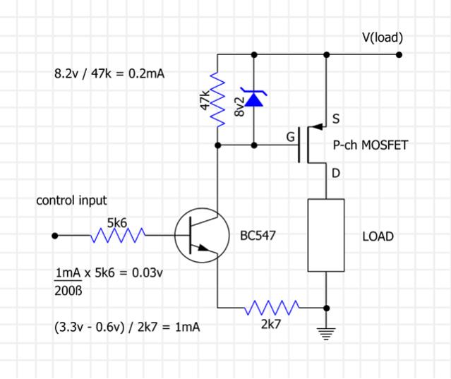 the BC547 and 2k7 resistor create a 1mA constant-current sink when the control input is high (3v3). along with the 8v2 zener diode this creates the gate voltage for the P-channel mosfet, limited to 8v2 to prevent exceeding the mosfet's Vgs(max). the 47k resistor ensures the mosfet turns off when the control input is low (hence minimal collector current through the BC547). meanwhile, the 5k6 resistor is included in case of V(load) being absent for some reason, limiting the current drawn from the control input to a few hundred microamps. V(load) is only limited by the rating of the mosfet and the Vce(max) of the BC547. if you wish to include an indicator LED, you could: 1. insert it between the collector of the BC547 and the gate of the mosfet, or, 2. insert it in series with the zener diode (and lower the zener's voltage to compensate), or, 3. connect it from the base of the BC547 to ground and adjust the 5k6 and 2k7 resistors accordingly. cheers, rob :-) |
||||
| LouisG Senior Member Joined: 19/03/2016 Location: AustraliaPosts: 130 |
Thanks a lot, Rob. I assume the phototransistor of the photocoupler can be substituted for the BC547. I'll breadboard a circuit to verify. Louis |
||||
| Quazee137 Guru Joined: 07/08/2016 Location: United StatesPosts: 603 |
Just a basic thoughts. 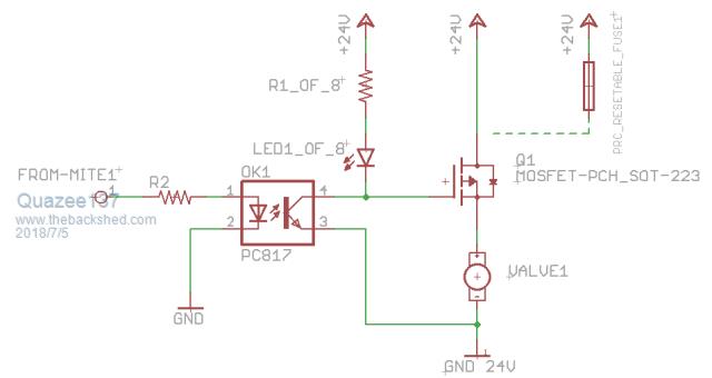 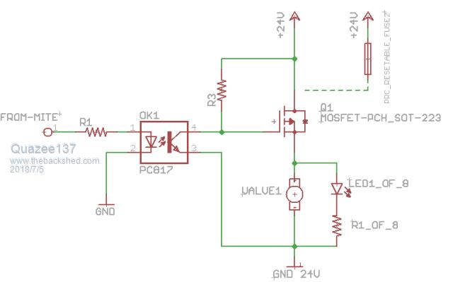 |
||||
| Page 1 of 2 |
|||||
| The Back Shed's forum code is written, and hosted, in Australia. | © JAQ Software 2026 |
