
|
|
Forum Index : Microcontroller and PC projects : A serial mystery....
| Page 1 of 2 |
|||||
| Author | Message | ||||
Grogster Admin Group Joined: 31/12/2012 Location: New ZealandPosts: 9975 |
This is very interesting. Serial @ 9600 baud. Device is a SIM7600SA 3G/4G Cell-phone module UART. CASE 1: I can connect to the device fine using an external MAX3232 fed from the same 5v supply as the device. No problems there, and everything works as expected. CASE 2: I cannot talk to the device at all, no matter WHAT I try, using a CP2102 USB-serial module. A loop-back test on the 2102 module works fine, and characters I type, appear on the terminal, so the VCP is up and running, and the 2102 is obviously working fine. But when connected to the device, it flatly refuses any attempts to talk to it.  The obvious swapping of one end of the serial link TXD/RXD has also been done in case I had the data lines the wrong way around, but no comms. The obvious swapping of one end of the serial link TXD/RXD has also been done in case I had the data lines the wrong way around, but no comms.THE ONLY THING I CAN THINK OF FOR NOW, is that for SOME reason, the device does not like being powered from a separate 5v supply to that of the 2102(which is powered from USB). Both the device and the 2102 have the same common ground though, so I would have thought it would have worked.  Does anyone have any ideas? I cannot power the device from the USB port, as it is thirsty. It sucks about 2A when it is logging onto the network, and when it is transmitting to the network. This is beyond the USB2 spec, so I am using a separate 5v supply for the device. The separate 5v supply is NOT a USB-charger. It is a Jaycar regulated 5v plug-pack. I also tried the 5v charger things just for the hell of it, but they did not work also - but I kinda expected as much. There output can be quite dirty..... Smoke makes things work. When the smoke gets out, it stops! |
||||
TassyJim Guru Joined: 07/08/2011 Location: AustraliaPosts: 6538 |
Do you have the signals inverted on one setup and not on the other? MAX3232 inverts. CRO on data lines needed! Jim VK7JH MMedit |
||||
| Grogster Admin Group Joined: 31/12/2012 Location: New ZealandPosts: 9975 |
Yes, great idea.  I will hook up my logic analyser to the data pins and reboot the module and see if it can capture any data. The module itself outputs plain TTL. From the module manual: "RXD/TXD are 3.3V TTL level which can be directly connected with 3.3V MCU." I was just using the MAX3232 module on COM1, as another way to talk to the module. That works. With that in mind, connecting the device to a 2102 USB-serial adaptor SHOULD work - but it doesn't. Grogster scratches his head..... EDIT: Here is the savecapture data. The device seems to be pulling the TXO line low and holding it there for 12 seconds before it outputs any data, which seems a little odd. I expect that perhaps THIS is confusing the 2102 unit? 2018-07-23_173311_250_kHz,_6_M_Samples_3.zip Smoke makes things work. When the smoke gets out, it stops! |
||||
| Grogster Admin Group Joined: 31/12/2012 Location: New ZealandPosts: 9975 |
This odd twelve-second low is also making it totally incompatible with the MM com port. I have wired it to an E28 for the purposes of testing, and the MM com port totally ignores the module. If I continue to connect this module via a 3232 level corrector to COM1 on the PC, it talks, but that is useless, as I need it to interface to the MM COM port. Not THAT impressed with this module, unfortunately.  The next thing I am going to do, is put the Salie Logic on the MM com port while connected to the module, and send it a text and capture the output. EDIT: This is getting interesting. With the logic analyser directly on the output of the module, it captures any text message I send to it. As soon as I put TXD onto the MM RXD, the line stays at 3v3 and never shifts. So, with it connected to the MM, and you send it a text message, NO DATA is received at all. Voltage across the module TXD and GND when idle, is 3.26v, which sounds right. Voltage across the module TXD and GND when connected to the MM RXD is also 3.26v, so the MM cannot be pulling the line down or anything, but if connected, no data, if NOT connected, data. Very odd..... I will now check the same idea with the logic analyser across the module and the CP2102 USB-serial adaptor that refused to work yesterday - I bet it is the same. My guess is that it is working on the MAX2323 module, as it is buffered, whereas the MM and the 2102 are not - it's right down the throat of the UART.Smoke makes things work. When the smoke gets out, it stops! |
||||
Azure Guru Joined: 09/11/2017 Location: AustraliaPosts: 446 |
I have just checked out the chip specs from simcomms web site. I have not been able to locate the schematic for the module you have but from the photos it looks like there are some series current limiting resistors on the Txd and Rxd lines and they then go stright to the chip. The chip uses 1.8V signal levels for the uart, so to talk to a MM it will need to be level shifted. If looking at it from a 3v3 or 5v mindset the signal will look low (between min 0.8v to max 1.8v for active high). Makes sense why the logic analyser sees and decodes it and not the MM. Page 27 of the hardware design manual shows somw simple transistor based llevel shifting for the uart Txd and Rxd pins. The chip startup time is around 15 seconds, there is a signal to indiciate it has started up, not sure if it is the k-pwr-key pin on that module, but again it would be 1.8v signal. If it is that pin you can check it has started up before you try and open it as a comm port on MM (after you have level shifted the Txd/Rxd and kpwrkey if that is the correct one). |
||||
| Grogster Admin Group Joined: 31/12/2012 Location: New ZealandPosts: 9975 |
Here is the schematic for the module I have: 2018-07-24_122107_BK-7600_Schematics_V1.pdf Here is the user manual for the module I have: 2018-07-24_122343_BK-SIM7600_Board_user_manual_V1.0.pdf The voltage between TXD and GND on the module measures as 3.26v though, not 1.8v.... I have downloaded the manuals myself now, so I will check out page 27. Don't go anywhere, Azure - I think I am gonna need you..... EDIT: User manual, page 5 says in red you can connect directly to a 3v3 MCU. Smoke makes things work. When the smoke gets out, it stops! |
||||
| Azure Guru Joined: 09/11/2017 Location: AustraliaPosts: 446 |
On the schematic U103 is a level shifter for Txd and Rxd. Thank goodness for that. Can you see the marking(s) on that chip so we can try and look it up. I will have a quick look re the startup indication. |
||||
| Grogster Admin Group Joined: 31/12/2012 Location: New ZealandPosts: 9975 |
Yeah, I just don't understand why the logic analyser sees the output, but as soon as you put the MM on it or a USB-serial adaptor, the data vanishes. I also tried putting a 4k7 in series with TXD from the module to the MM, and the logic analyser then sees the data again, but the MM does not. U103 is marked as "NFDR" - I will search for that now too. Annoyingly, the schematic does not give any part values.  Smoke makes things work. When the smoke gets out, it stops! |
||||
| Azure Guru Joined: 09/11/2017 Location: AustraliaPosts: 446 |
I lied is it 12 seconds before the uart is operational after startup. The startup indication is pin is called Status on pin 49. It is not connected on that module. There is something going on with the Dtr pin connected to 1v8 via a resistor or pulled to ground via a net labelled sleep1. the only other sleep I can see is on pin 0 of CN101 which I think is the main module interface. |
||||
| Grogster Admin Group Joined: 31/12/2012 Location: New ZealandPosts: 9975 |
The U103 device appears to be a TXB0102DCUR Link to PDF. It is a bi-directional dual voltage level shifter - exactly what we need there, so that is good. I've never touched the SLEEP line, even when I had it hooked up via a 2323 and COM1 on the PC. All I can see that SLEEP does, is that if you put a high on that, it will pull DTR on the module down, so telling the module that the terminal is not ready to receive any data - an odd way to 'Sleep' a module. R135 pulls DTR up normally, so the module should think that the DTE is always available unless you pull SLEEP pin high. EDIT: I have now checked the module with a CP2102 module connected to it, and the exact same thing happens - the TXD line stays at 3v3 forever, so there are no comms. Disconnect from CP2102 module, and send a text and the logic analyser sees it fine. Pretty useless if you can't actually connect anything to the UART on this thing. I almost get the impression that U103 does not have the ability to pull the output 3v3 line down at all. It obviously works with the logic analyser on it, as it will be a relatively high impedance load, but the MM or the CP2102 might not be, so the line stays high forever. The investigation continues.... Smoke makes things work. When the smoke gets out, it stops! |
||||
| Azure Guru Joined: 09/11/2017 Location: AustraliaPosts: 446 |
Just an on the fly observation while reading the document and the schematic. The level shifter and the module wiring to it seems ok (as you would expect for a working design). However it states that there should be no pullups and if there is anything it should be at least 50K. Section 8.3.3 and 8.3.5 of the level shifter spec talk about capacitive and resistive loading on the outputs. Might need to look at how it connects into MM and the pins being used. |
||||
| Grogster Admin Group Joined: 31/12/2012 Location: New ZealandPosts: 9975 |
Yeah, I have been reading my way through the level shifter PDF myself, and read the same. It would seem that this level shifter is pretty gutless and can't really drive more then a few microamps which is probably not enough to really do anything externally. I am looking to see if I have something like a 74HC4050 buffer that I could hook up to it, but that really should NOT be necessary if they had designed the module right in the first place. Oh well, such is life. Smoke makes things work. When the smoke gets out, it stops! |
||||
| Azure Guru Joined: 09/11/2017 Location: AustraliaPosts: 446 |
It is spec'd to be able to drive 50mA, so it should not have a problem. At 3v3 on VccB (as on the module) it is able to transmit at up to 100Mbps so I expect those minimal loading values are to keep the rise and fall times nice, short and sharp. So how is it connecting to the MM and what pins? A useful exercise may be to drive the Module Rxd from your MM Txd (send data to it) and send it AT commands and see how it responds using the logic analyser or scope to monitor the module Txd (not connecting Txd to your MM). Edit: You do of course realise it is going to be something silly when what is going on is finally figured out. |
||||
| Grogster Admin Group Joined: 31/12/2012 Location: New ZealandPosts: 9975 |
Nice one, so I don't need a buffer then - it should be able to cope fine. That's more in line with what I would expect. I am using COM1 on the MM - pins 21 and 22. No external pull-ups, directly connected. But if I put the module on a CP2102 USB-serial adaptor, it ALSO refuses to talk to it, and when I tested that setup with the logic analyser too, I had the exact same problem in that TXO never goes to 0v, so no data ever makes it across the link. I will try your idea of splitting it between MM and logic analyser, and get back to you. Smoke makes things work. When the smoke gets out, it stops! |
||||
| Grogster Admin Group Joined: 31/12/2012 Location: New ZealandPosts: 9975 |
Progress - perhaps? I get a result with that configuration. 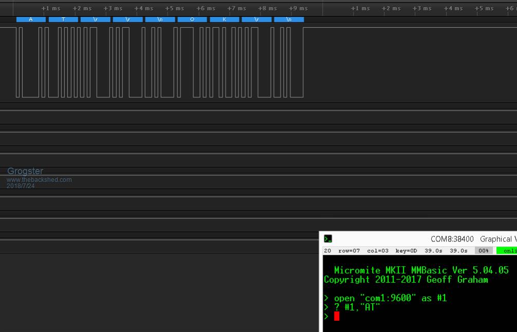 I can SEND it a message from the MM, and I can read back the "OK" it said in response, to the logic analyser, but not on the MM or any USB-serial adaptor. Something odd going on with the TXD from the module. I'm kinda lost now. |
||||
| Azure Guru Joined: 09/11/2017 Location: AustraliaPosts: 446 |
A bit more reading (RTFM) to dig further into the matter: MM Manual Pages 85 & 86 The module being used does have series resistors on both Txd and Rxd. So there are 2 options: Software - give the ChangePin routine a try; Hardware - short out the series resistor (should only need to do the modules Txd pin). If you do short it out, try and do it nicely so you can put it back the way it was if needed after things are sorted out. Just out of curiosity, what is the value of the series resistor? Edit: Just saw your post with your promising results, looks like things are heading the right direction. This make sense together with the above information. |
||||
| Grogster Admin Group Joined: 31/12/2012 Location: New ZealandPosts: 9975 |
Good idea, Azure. I had forgotten about that, what with trying to work out why the hell it won't work. I will do just that, and let you know if I have any success. I have no idea of the value of the series resistor. They are just called R118 and R119, but no values are stated. Smoke makes things work. When the smoke gets out, it stops! |
||||
| Azure Guru Joined: 09/11/2017 Location: AustraliaPosts: 446 |
So, a little more reading across the module and chip specs. Note: Both of the following signals are 1.8v logic level signals. The Sleep input is used to wake up the unit if it goes to sleep (apparently pulling TDR low will wake the chip up from sleep). The PwrKey will put the unit to sleep. These pins on the module can be left unconnected unless you want to use these functions. You could measure R118 and R119 with a meter while they are not connected to anything (if the value is not printed or to small to read on them). Just peace of mind stuff to see what the voltage divider would be with the MM internal pullup. |
||||
| Grogster Admin Group Joined: 31/12/2012 Location: New ZealandPosts: 9975 |
Yes, I will find a way to measure them - they are tiny, but under the scope I think I could measure them with needles for meter probes.  EDIT: Both those series resistors are 1k. Smoke makes things work. When the smoke gets out, it stops! |
||||
| Azure Guru Joined: 09/11/2017 Location: AustraliaPosts: 446 |
Well based on those values and the MM internal pullup values everything should be ok. I was hoping they would be something much higher. ...One step backwards. I would not bother shorting the resistor and try the ChangePin function first. Edit: Without taking the thread off track, what logic analyser are you using and how hard is it to trigger? seems much nicer than the old one I have. |
||||
| Page 1 of 2 |
|||||
| The Back Shed's forum code is written, and hosted, in Australia. | © JAQ Software 2026 |
