
|
|
Forum Index : Electronics : recycling those Aerosharp chokes
| Author | Message | ||||
renewableMark Guru Joined: 09/12/2017 Location: AustraliaPosts: 1678 |
Nothing wrong with caveman style. Cheers Caveman Mark Off grid eastern Melb |
||||
| Tinker Guru Joined: 07/11/2007 Location: AustraliaPosts: 1904 |
If you do lots of wires then Gaspo's gadget is the way. I'm happy to scrape the enamel off, easy enough with wires thicker than 1mm but a pain with smaller ones. I have an old triangular file which has its teeth ground off to make a scraper. Hold it sideways to the grinding wheel (bench grinder) to make a slightly hollow surface and sharp corners. This is followed with emery cloth. I do not think steel wool is a great choice, prefer emery cloth above that every time. Klaus |
||||
mackoffgrid Guru Joined: 13/03/2017 Location: AustraliaPosts: 460 |
 I was not intentionally making any reference to you Mark, and if caveman style is a reflection of how you make transformers then indeed there is nothing wrong with Caveman style. I was not intentionally making any reference to you Mark, and if caveman style is a reflection of how you make transformers then indeed there is nothing wrong with Caveman style.  I don't have to tell you guys that the enamel on the wire of the aerosharp (and like) transformers is quite hard. I've tried acetone, heating an aspirin tablet, and probably a few other dumb ideas, in the end I found heating the enamel (charring) - I used a map gas torch, and the steel wool virtually just wiped the enamel off. I agree that steel wool is ineffective on the untreated enamel wire. I don't have the sort of files you describe and when faced with the multiples of enamel wire I just didn't want to use the pocket knife to scratch the enamel off. I guess I was looking for the simple magic bullet like dipping the wire into a magic solution of household chemicals and hey presto the enamel fell off That stripping tool does look interesting - I'll put it on my Christmas list. Cheers Andrew |
||||
| Warpspeed Guru Joined: 09/08/2007 Location: AustraliaPosts: 4406 |
There is in fact a magic brew that does exactly that, but its really evil stuff. Don't know what's in it but its a thickish paste, and when you unscrew the lid of the bottle, these evil tendrils of really strong acid fumes emerge. A quick soak, and a wipe with a rag, and nice pink bare copper wire results. Had it for years but never use it, it scares me to death. Its some French brew, maybe Clockman knows something about it. 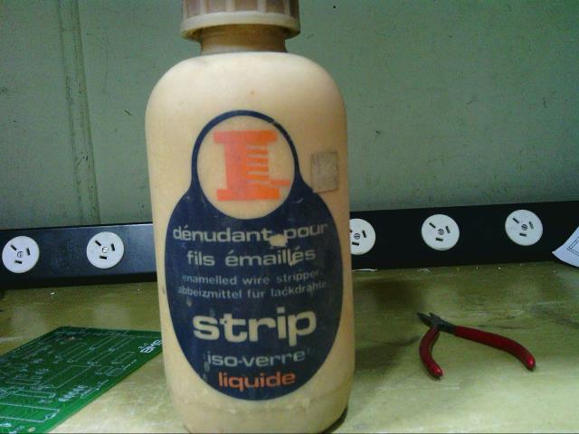 Cheers, �Tony. |
||||
| renewableMark Guru Joined: 09/12/2017 Location: AustraliaPosts: 1678 |
No worries Mack, just clowning around. I just use sidecutters and gently pinch it and scrape it off, move to another angle and scrape again, should only take 20 seconds to make it clean. Tony anything that can work that well must be nasty, probably banned now for being carcenogenic. Cheers Caveman Mark Off grid eastern Melb |
||||
| Tinker Guru Joined: 07/11/2007 Location: AustraliaPosts: 1904 |
Now that is an interesting idea, I might try that. I would somehow lock the handles so the jaws form a 'V'. That way its not possible for Murphy to distract you and you accidentally cut the wire  . .That 'V' would self adjust any wire diameter. Klaus |
||||
| renewableMark Guru Joined: 09/12/2017 Location: AustraliaPosts: 1678 |
If you hold the handle towards you so the blades are at an angle of 30-45 deg then they can't actually bite into the material, they just scrape. A little bit like peeling a potato. Very hard to describe in words, you'll get it when you try it. Cheers Caveman Mark Off grid eastern Melb |
||||
| ltopower Regular Member Joined: 08/03/2019 Location: United KingdomPosts: 64 |
Really like the idea of using copper foil.... makes a lot more sense to pack the copper in, however, this is what I ended up with : 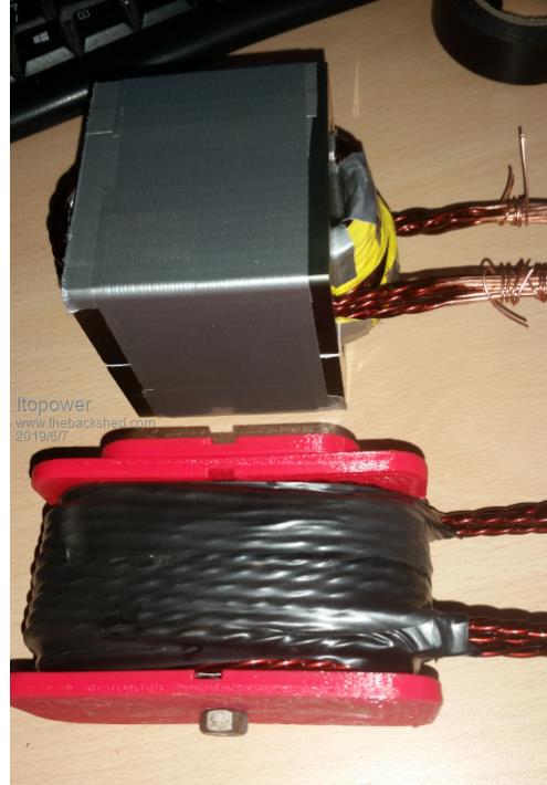 I 3D printed a former to wind the 3x3x3 wires on before slotting the twin gapped E70 cores in. 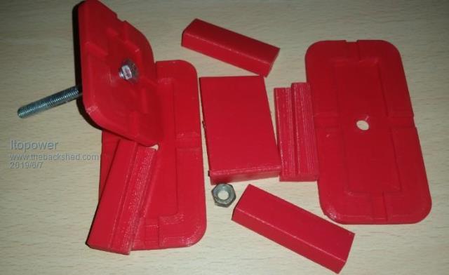 Each one was 120uH and used two in parallel 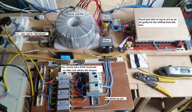 At some point I need to open up the airgap more and reduce the inductance down as the idle current is higher than I would like (and opening the gap will give higher saturation). What I found from my testing was a higher inductance (300uH and higher) caused issues with the switching causing ringing/oscillations. More concerning were the oscillations at switch off and a different effect the high inductance had on the board at no load. |
||||
Revlac Guru Joined: 31/12/2016 Location: AustraliaPosts: 961 |
Nice looking layout. The wave form would have looked a bit strange on a scope screen I bet. I also found a very similar result when using a large EI for a choke, It was wound with copper strap. The wave form was also looking horrible, But after increasing the air gap it cleaned up rather nicely. I like the former too.  How many turns you have on those chokes? Cheers Aaron Off The Grid |
||||
| wiseguy Guru Joined: 21/06/2018 Location: AustraliaPosts: 1001 |
When I saw the "board laid on top to act as a " I expectd it to go on to say "shield to protect me from flying plastic bits and flames" lol - it should make a reasonable wind tunnel though - or flame thrower if it all goes wrong... I liked the 3D 'print my own former' approach, quiet novel - in a lot of my earlier designs I used a similar approach with PCBs, snap off bits were designed to became drill quides, spacers, insulators, shielded enclosure boxes, raised current carrying buses etc etc. Nice looking test bed - if it runs as good as it looks you should be happy. I hope you'll forgive my poor attempt at humour. PS I saw in a separate post your pictures of your Lithium Titanate battery setup, that was really quite impressive - and a lot of links and a lot of nut tightening...... 2 per cell for was it 450 odd batteries ? If at first you dont succeed, I suggest you avoid sky diving.... Cheers Mike |
||||
| ltopower Regular Member Joined: 08/03/2019 Location: United KingdomPosts: 64 |
Yeah, the board could act as a nice furnace duct. I was thinking more of a guard to stop the molten PCB tracks and FET's from going everywhere. The board is fed with a 160A breaker, which I'm guessing will not trip before the tracks have been blown off the board.... The 3D print was after a few tests with various bits of wood, plastic and paper, trying to wind a tight shape and still able to get the wood/parts out and have the right shape. The multiple layers ended up being the issue trying to get them into the right position for the gap with just wood was going to take way more time and patience than I had. The picture was the second version, the first was for a single E70. The center part is tapered as well so that it can be tighened up easily and the corner parts could do to be a bit longer/wider as they bend a small bit with the wire pressure. Worked ok winding the cores, although I would not twist the wires next time round and glue them in place taking more time to wind them as the twisted wires take up a lot more space. 10 turns, 9 wires, pre-twisted into 3 sets of 3. The LTO packs are 11 in series 2 parallel each (22 cells per pack) and there are 18 packs, 396 cells, nut each end and 12 alloy join plates per pack. Approx 36kWh. The nuts were the least of the issue, the D-Connectors on each pack had to be soldered up, along with around 500m of cable for the connectors and cable to join them together through fuses and 0.27 ohm resistors (to decrease any high current surge on small voltage differences when connecting). The more complete details on the packs, cells and build is here : https://secondlifestorage.com/t-LTO-Powerwall |
||||
| mackoffgrid Guru Joined: 13/03/2017 Location: AustraliaPosts: 460 |
This is the choke I wound for the 26V WarpVerter. Uses two large AeroSharp choke cores. It's wound with 11.5 turns x 18 of 2.5mm2 wire, 45mm2. Wound three in hand, 11.5 turns per layer, six layers. Ended up being 70uH with a 1.6mm gap. This ended up a lot bigger than I thought it would. 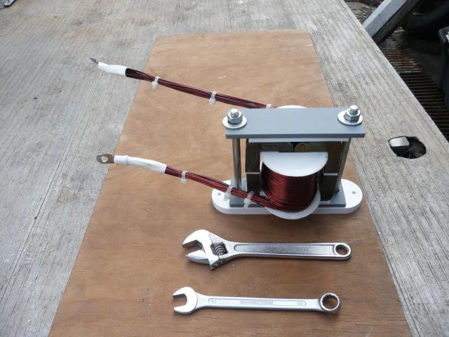 I do have access to an old metal lathe but have no idea how to use it. So I embarked on winding the choke in a way I understand. I have to say that Tinker's method of winding the choke is a far superior method to what I did but here goes. I wanted to be able to hand wind a choke based on two of those large AeroSharp cores. So, using a 3D printer I printed a former I could wind the wire onto. 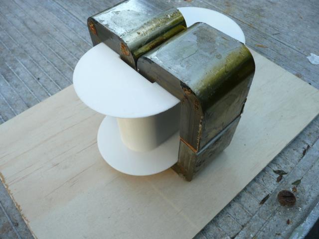 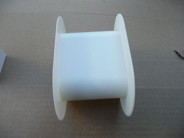 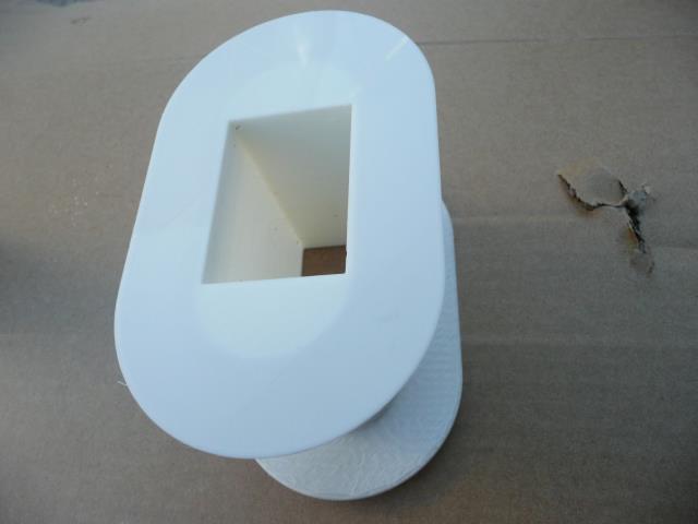 Then I needed a way to hold the former into a bench vice. 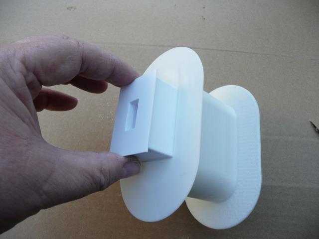 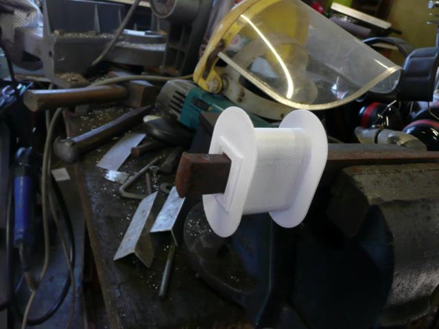 Winding three in hand, 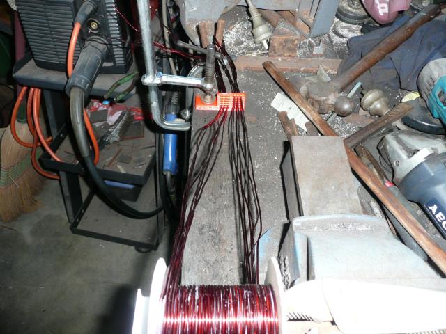 Also printed a block to hold the wires individually just to make winding a bit more sane. Taking Tinkers instructions, I coated each layer with epoxy (I thickened it with talc) 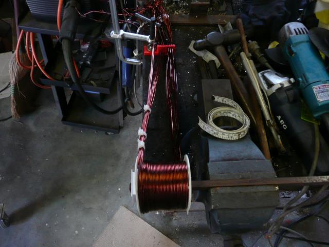 I took close-up photos of each layer so I could do a Turns counts with ease. (Closer than above) Winding Done. 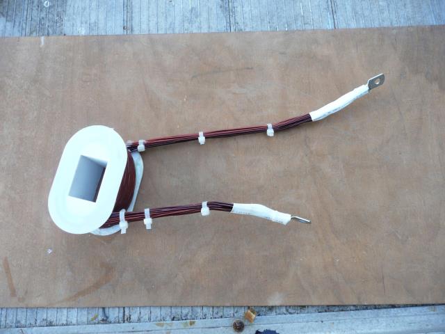 3D printed some insulating panels and a base plate. Bolt heads are embedded into the base plate. 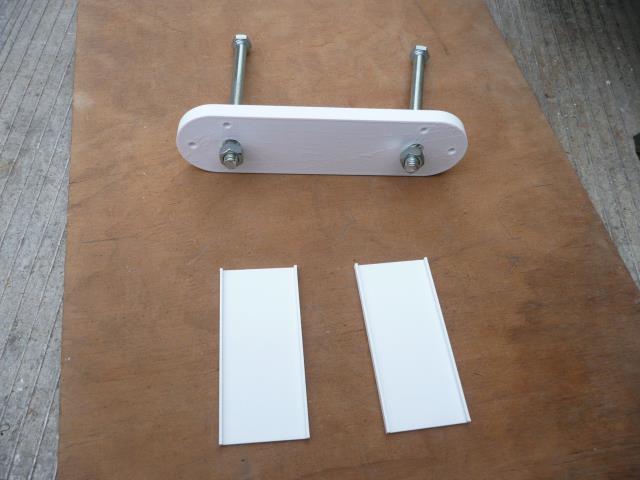 To sum up: This worked well, but it would have been neater and tighter done on a lathe. If I had to many more I'd definitely try to work the lathe out. I really dis-like the flaky steel these cores are made. Countless splinters !! Leaves thin sheets of metal flakes everywhere. Would be worth considering giving it a coat of epoxy straight after dismantling. All up it was a bit laborious and for those not retired it may be easier to buy cores from AEM cores $25 to $35 for a core big enough to use welding cable. Cheers Andrew |
||||
| kentfielddude Regular Member Joined: 09/05/2019 Location: United StatesPosts: 89 |
Lto batterys have a discharge efficiency of 85% where as Lifepoe4 is around 99% discharge efficiency |
||||
| BenandAmber Guru Joined: 16/02/2019 Location: United StatesPosts: 961 |
Wow I'm impressed be warned i am good parrot but Dumber than a box of rocks |
||||
| Tinker Guru Joined: 07/11/2007 Location: AustraliaPosts: 1904 |
???????? Got your topic mixed up?  Klaus |
||||
| Tinker Guru Joined: 07/11/2007 Location: AustraliaPosts: 1904 |
Very nice Andrew and a 3D printed former to boot! I had no idea these toys could also do useful things  . .But your winding method has me baffled. The 'hold in the vise' thingy is not rotating and you seem to start in the middle of the coil and wind both ends at the same time in opposite direction? Is that so both ends come out on top? Must be tricky to control the long wire ends at the start of winding. I wind mine in single layers 2 in hand. There are 6 or more layers,one on top of the other, depending on the space available. Each layer starts at one side and ends at the other side of the former. A tip; no need to use thickener (talc, etc.) when epoxying windings. You want the stuff thin to run in between the wires. It does require some drip catching if its done on a lathe though. Doing it on a lathe is very much different than doing it by hand. You get very neat side by side wires but that needs more tension than, perhaps, that printed former could stand. I use a dismantleable metal former but for just one choke making this takes way more time than the winding does .Agree with you re the nasty sharp metal flakes, one took a powerful magnifying glass and a scalpel to dig out of my fingertip. Leather gloves do help when handling the cores. Klaus |
||||
| mackoffgrid Guru Joined: 13/03/2017 Location: AustraliaPosts: 460 |
It came out better than I thought I could manage, so was very pleased. It wasn't perfect and I can see how a lathe would be far superior. Nothing clever about how I wound it - and yes the long tails were a pain until you got some of the wire on the former, about as long as I'd like to handle. I do like the 3D printers, we have 2 now Keep finding useful things to make. I agree a 3D printed former is not likely to handle the forces you can exert using a lathe especially with larger wire sizes. Having said that, I think if you use an intermediate, tapered sleeve that pads and is sacrificial, it may be possible to use a 3D printed former.When you wind a choke using the lathe do you put the wire on a reel? Do you use one reel per wire? How do you tension the wire? Cheers Andrew |
||||
| Warpspeed Guru Joined: 09/08/2007 Location: AustraliaPosts: 4406 |
I have a suitable lathe here rigged up with a turns counter, but for something that requires only a very few turns on one layer, I would just as soon use the held stationary in a vise method. Very jealous of your 3D printing, might look into all that myself one day. Too many projects, too little time...........! Cheers, �Tony. |
||||
| Tinker Guru Joined: 07/11/2007 Location: AustraliaPosts: 1904 |
The wire is laid as a lightly coiled (~250mm dia) bunch on a stand a bit away from the lathe but in line with the tool holder. The wire was first cut to the calculated length required + 0.5m for clamping until the epoxy hardened. Wire tensioning: 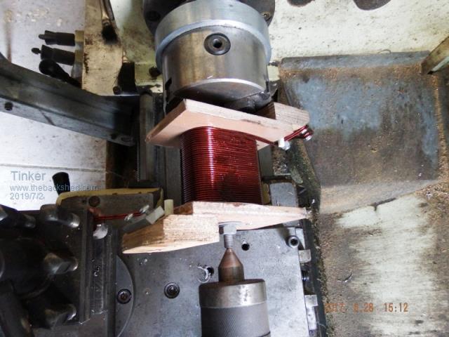 The picture shows an early attempt of lathe wiring, using a wooden former - this former was NBG. You can see the wire tensioned in the tool holder (bottom left corner). It is run through a shallow grooved bakelite pad and clamped on top by a matching hardwood block which is tensioned by the tool holder bolts. The bakelite pad requires a cutout to lock it against the tool post or it will be pulled out by the wire. I do *NOT* use the motor for this. The chuck is turned by hand with a lever inserted between the chuck jaws. I DO use the screw threading feed to advance the tool post in step with the turn pitch. One of the available threading ratios usually suits, if not exact, small adjustments can be made with the compound slide. This method also requires a very substantial wire clamp for the start of the coil. Until at least one full turn is on there is a lot of pulling on this. The metal former comes on its own when using 2mm wire or so, one can use a hardwood block and hammer to flatten the wire against the former on the flat side. No problems at the turns, the wire tension lays the wire neatly there. If you want more pics or info just ask. Klaus |
||||
| mackoffgrid Guru Joined: 13/03/2017 Location: AustraliaPosts: 460 |
I think I have the gist, I'll run this by my machinist mate. My brother bought the lathe off a family friend who is now deceased, and we know very little about how to use it . And Tony inferred, so many projects, so little time . Cheers Andrew |
||||
