
|
|
Forum Index : Microcontroller and PC projects : Picromite Aug 18
| Page 1 of 2 |
|||||
| Author | Message | ||||
lew247 Guru Joined: 23/12/2015 Location: United KingdomPosts: 1709 |
Hi Peter I "think" I've found a bug with the Picromite, it "may" be an error with my soldering but I don't think so When I attach an SSD1963 display (7 inch) it works ok other than the touch will not calibrate I thought I'd messed the display up when I tried to move the jumper for the backlight so I bought 2 new ones and both of them are doing the same thing. I was about give up and get another display when I suddenly had the idea to try calibrating it with my Explore 100 board and it calibrates perfectly with no errors. This is the error - it appears after touching the 2nd touch point in the calibrate routine 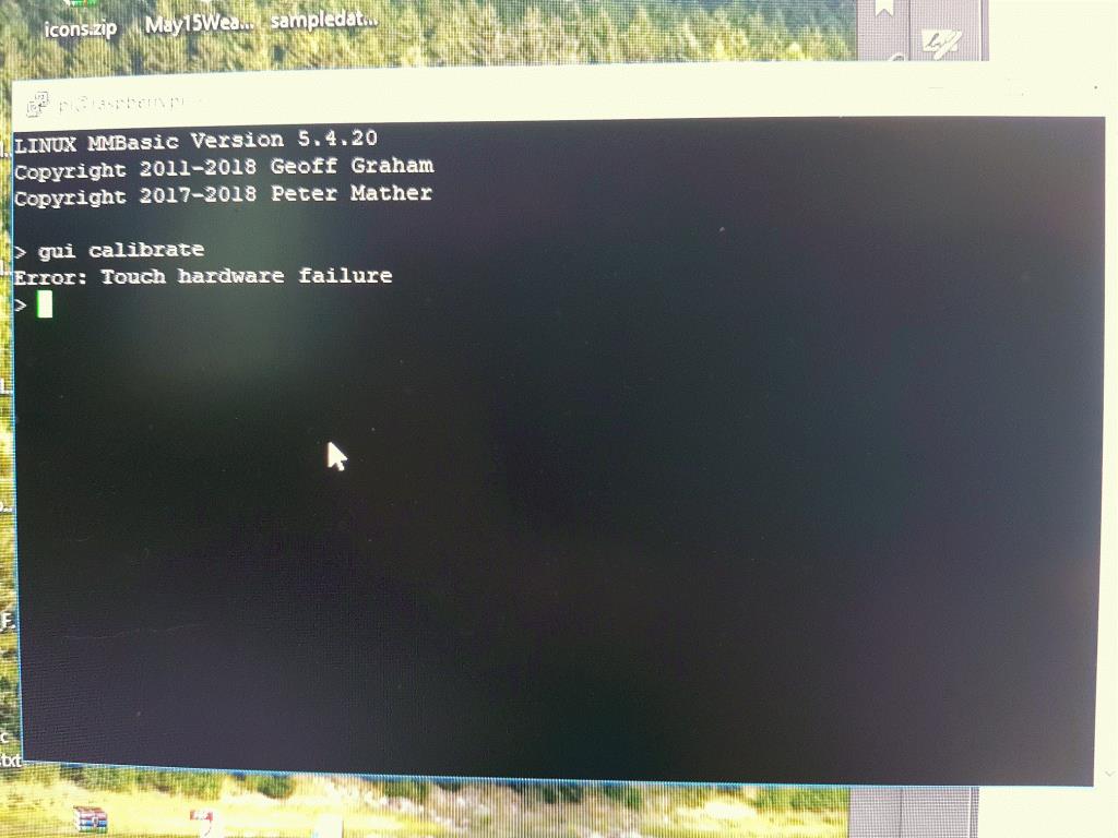 btw IF this is an error and do release an updated version, any chance of the gauges that are in the latest MM test version? they look really simple to implement for someone as useless at programming as me |
||||
| matherp Guru Joined: 11/12/2012 Location: United KingdomPosts: 11499 |
Just tested 5.4.20 on a Pi-Zero and it works fine. I'm using Grogster's backpack to connect the display: Option lcdpanel SSD1963_5,l,,36 Option touch 26,24 Will include the new controls when Geoff releases the source at the end of the beta period Check SPI wiring: T-DIN - 19 T-DOUT - 21 T-CLK - 23 |
||||
| lew247 Guru Joined: 23/12/2015 Location: United KingdomPosts: 1709 |
Thanks Peter |
||||
| lew247 Guru Joined: 23/12/2015 Location: United KingdomPosts: 1709 |
I just redownloaded 5.4.20 in case I was using an older version and reinstalled it Deleted the Options file and when I go to calibrate the touch I still get the same error This is the relevant part of the circuit and I'm pretty sure it's correct 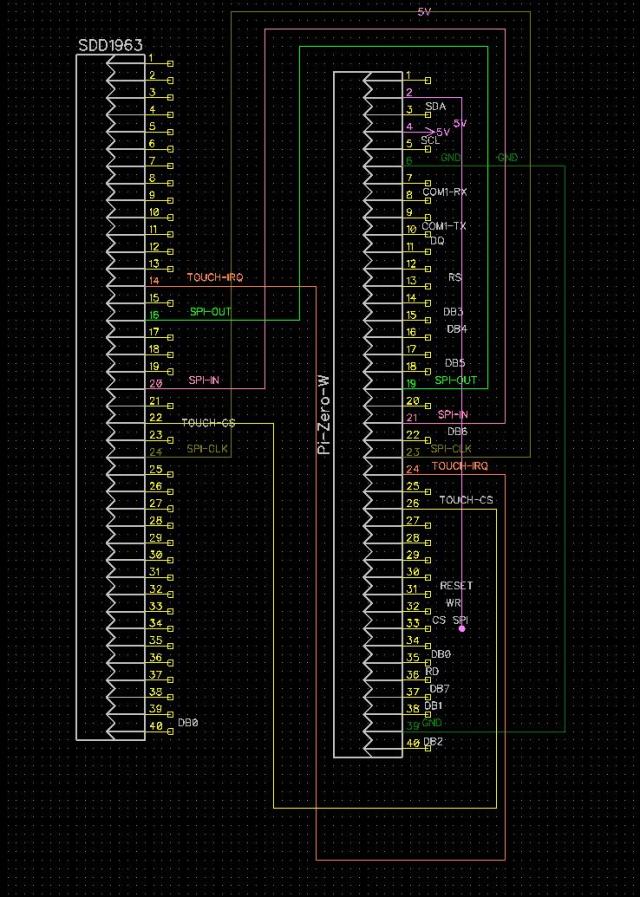 |
||||
| matherp Guru Joined: 11/12/2012 Location: United KingdomPosts: 11499 |
16 is T_DO which should be connected to SPI_IN 20 is T_DIN which should be connected to SPI_OUT |
||||
| lew247 Guru Joined: 23/12/2015 Location: United KingdomPosts: 1709 |
According to the manual 21 DIGITAL_IN DIGITAL_OUT SPI-IN 19 DIGITAL_IN DIGITAL_OUT SPI-OUT On the SSD1963 pin 16 T_DO is connected to pin 19 on the Picromite pin 20 T_DIN is connected to pin 21 on the Picromite so it should be working |
||||
| matherp Guru Joined: 11/12/2012 Location: United KingdomPosts: 11499 |
If it was right it would be working T_DO (pin 16 of the SSD1963 in your diagram) is the output of the touch controller it connects to SPI-IN T_DIN (pin 20 of the SSD1963 in your diagram) is the input to the touch controller it connects to SPI-OUT Your diagram above is incorrect - the signals are swapped. Check Grogster's PCB which is correct 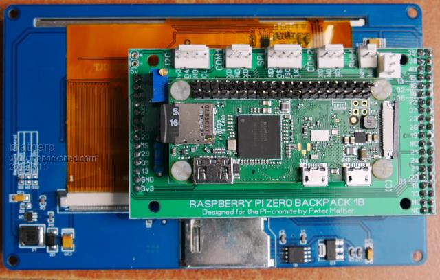 |
||||
goc30 Guru Joined: 12/04/2017 Location: FrancePosts: 435 |
Hi all I have a "small" problem I need a LCD Font. With micromite, i use an additional font who is loaded in src named "SevenSegNumFont.bas" with zoom=3. Font 6 in zoom*3 is too ugly, and actual font 7 is too small is it possible to have same proc (or other think) in picromite thank In a few days, I will tell you about my communication experiences in I2C with rpi and pic (rpi-pic-pic or picmz-picmx etc ..) and... gps |
||||
| lew247 Guru Joined: 23/12/2015 Location: United KingdomPosts: 1709 |
Back to BLIT I've tried all combinations or Matherp's suggestion [quote]do option autorefresh off ' optional reduces artifacts BLIT WRITE compass background write the pointer option autorefresh on 'optional reduces artifacts refresh 'optional reduces artifacts loop[/quote] but it will not work on the Picromite. The compass pointer moves, but it does not refresh the picture before writing the new compass direction so it ends up with loads of pointers on the screen 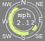 The following code works perfectly on the E100 but not the Picromite, and as far as I'm aware the BLIT command does not change for either version. [code] 'Subroutines to make the compass pointer move to the correct position Sub moveto(angle As integer) Local integer xs=x, ys=y, ws=w, hs=h rotatetriangle(angle,0,radius,x0,y0,x1,y1,x2,y2) pxx0=xx0+pivot_x pyy0=yy0+pivot_y-radius pxx1=xx1+pivot_x pyy1=yy1+pivot_y-radius pxx2=xx2+pivot_x pyy2=yy2+pivot_y-radius getlimits(x, y, w, h) ' blit write and blit close first time in will error so skip On ERROR SKIP 2 Blit read #1, x, y, w, h Blit WRITE #1, xs, ys, ws, hs 'restore the save background Blit close #1 Blit read #1, x, y, w, h Triangle pxx0, pyy0, pxx1, pyy1, pxx2, pyy2, RGB(215,255,119), RGB(215,255,119) 'COLOUR OF TRIANGLE End Sub Sub getlimits(x As integer, y As integer, w As integer, h As integer) Local integer i,max_x=0,min_x=MM.HRes,max_y=0,min_y=MM.VRes If(pxx0(i)>max_x)Then max_x=pxx0(i) If(pxx1(i)>max_x)Then max_x=pxx1(i) If(pxx2(i)>max_x)Then max_x=pxx2(i) If(pxx0(i)<min_x)Then min_x=pxx0(i) If(pxx1(i)<min_x)Then min_x=pxx1(i) If(pxx2(i)<min_x)Then min_x=pxx2(i) If(pyy0(i)>max_y)Then max_y=pyy0(i) If(pyy1(i)>max_y)Then max_y=pyy1(i) If(pyy2(i)>max_y)Then max_y=pyy2(i) If(pyy0(i)<min_y)Then min_y=pyy0(i) If(pyy1(i)<min_y)Then min_y=pyy1(i) If(pyy2(i)<min_y)Then min_y=pyy2(i) x=min_x y=min_y w=max_x-min_x+2 h=max_y-min_y+2 End Sub ' ' Simple trig to rotate the vertices of a triangle ' specified as x0,y0,x1,y1,x2,x2 relative to coordinate 0,0 ' by the angle specified ' and then translate them about the supplied real centre x,y ' the calculated coordinates are then placed into element n of a set of coordinate arrays ' Sub rotatetriangle(angle As float, x As integer, y As integer, x0 As integer, y0 As integer, x1 As integer, y1 As integer, x2 As integer, y2 As integer) Local float sine=Sin(Rad(angle)),cosine=Cos(Rad(angle)) Local integer x0a,y0a,x1a,y1a,x2a,y2a x0a= x0*cosine - y0 * sine + x y0a= y0*cosine + x0 * sine + y x1a= x1*cosine - y1 * sine + x y1a= y1*cosine + x1 * sine + y x2a= x2*cosine - y2 * sine + x y2a= y2*cosine + x2 * sine + y xx0=x0a yy0=y0a xx1=x1a yy1=y1a xx2=x2a yy2=y2a End Sub '*******End of compass routine *******************************[/code] |
||||
| matherp Guru Joined: 11/12/2012 Location: United KingdomPosts: 11499 |
The code as given above can't possibly work on the E100. The first thing it does is read the screen which has the pointer from the previous time and then write it back to the screen in a different position  Blit read #1, x, y, w, h Blit WRITE #1, xs, ys, ws, hs 'restore the save background If you follow my recipe it WILL work OUTSIDE THE LOOP write the complete compass without a pointer BLIT READ area overlapping the complete compass, i.e. the compass background do BLIT WRITE compass background write the pointer loop |
||||
| lew247 Guru Joined: 23/12/2015 Location: United KingdomPosts: 1709 |
Peter, I must me missing something obvious because I cannot get it to work Outside the sub, once the new weather forecast comes it it goes to the sub Sub moveto(angle) Then the sub Sub moveto(angle As integer) processes this I have tried ' blit write and blit close first time in will error so skip On ERROR SKIP 2 Blit read #1, x, y, w, h Blit WRITE #1, xs, ys, ws, hs 'restore the save background Blit close #1 Blit read #2, x, y, w, h do Blit WRITE #2, xs, ys, ws, hs 'restore the save background Triangle pxx0, pyy0, pxx1, pyy1, pxx2, pyy2, RGB(215,255,119), RGB(215,255,119) 'COLOUR OF TRIANGLE loop Blit close #2 ' blit write and blit close first time in will error so skip On ERROR SKIP 2 Blit read #1, x, y, w, h Blit WRITE #1, xs, ys, ws, hs 'restore the save background Blit close #1 Blit read #1, x, y, w, h do Blit WRITE #1, xs, ys, ws, hs 'restore the save background Triangle pxx0, pyy0, pxx1, pyy1, pxx2, pyy2, RGB(215,255,119), RGB(215,255,119) 'COLOUR OF TRIANGLE loop Blit close #1 ' blit write and blit close first time in will error so skip On ERROR SKIP 2 Blit read #1, x, y, w, h Blit WRITE #1, xs, ys, ws, hs 'restore the save background Blit close #1 Blit read #2, x, y, w, h Blit WRITE #2, xs, ys, ws, hs 'restore the save background Triangle pxx0, pyy0, pxx1, pyy1, pxx2, pyy2, RGB(215,255,119), RGB(215,255,119) 'COLOUR OF TRIANGLE Blit close #2 ' blit write and blit close first time in will error so skip On ERROR SKIP 2 Blit read #1, x, y, w, h Blit WRITE #1, xs, ys, ws, hs 'restore the save background Blit close #1 Blit read #1, x, y, w, h Blit WRITE #1, xs, ys, ws, hs 'restore the save background Triangle pxx0, pyy0, pxx1, pyy1, pxx2, pyy2, RGB(215,255,119), RGB(215,255,119) 'COLOUR OF TRIANGLE Blit close #2 And several other combinations but I just cannot get it to work Unless it's like the original post above I get  |
||||
| lew247 Guru Joined: 23/12/2015 Location: United KingdomPosts: 1709 |
Peter Would it be because of this in the MM+ manual>? [quote]The display must use the ILI9341 controller or the SSD1963 controller with the RD (read) pin connected (or VGA on the Micromite eXtreme).[/quote] On the Picromite that pin is tied to +3.3v |
||||
| lew247 Guru Joined: 23/12/2015 Location: United KingdomPosts: 1709 |
I've just soldered up a new board and I'm convinced I have the pins correct but I'm still getting the exact same "Hardware Failure" when I try calibrating the touch The top 2 calibration points calibrate perfectly, it's when I touch the 3rd point I get the error Could anyone check this circuit and tell me if it's correct please? 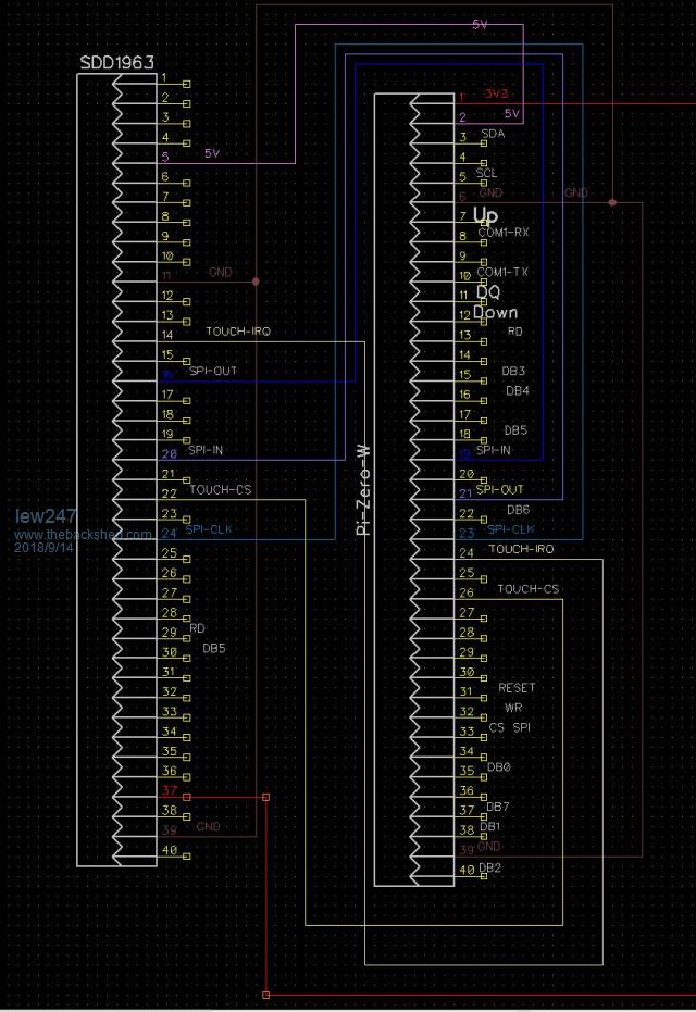 |
||||
| Frank N. Furter Guru Joined: 28/05/2012 Location: GermanyPosts: 1102 |
It seems that you confused SPI-IN and SPI-OUT on the Raspberry side: 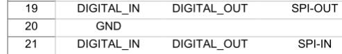 You have SPI-IN on 19 and SPI-OUT on 21... Frank |
||||
| matherp Guru Joined: 11/12/2012 Location: United KingdomPosts: 11499 |
Not sure, the problem is that the diagram shows the connectors as SIL whereas they are both DIL so it is very difficult to check properly As I said before the best thing is to exactly copy Grogster's board which is correct. T-CLK connects to Picromite pin 23 T-CS connects to Picromite pin 26 T-DIN connects to Picromite pin 19 T-DO connects to Picromite pin 21 t-IRQ connects to Picromite pin 24 Then OPTION TOUCH 26,24 |
||||
| lew247 Guru Joined: 23/12/2015 Location: United KingdomPosts: 1709 |
The connectors are just the ones I found on Diptrace They are the correct connectors on the board and everything else works perfectly The touch even works when calibrating PARTLY the first 2 calibration points work When touching the 3rd point that's when I get the "Hardware Failure" message I would have thought if I had the pins wrong then touch wouldn't work at all? |
||||
| matherp Guru Joined: 11/12/2012 Location: United KingdomPosts: 11499 |
No, you get exactly this result if the T_CS pin is not connected |
||||
| lew247 Guru Joined: 23/12/2015 Location: United KingdomPosts: 1709 |
I got rid of every other trace, leaving only the T_CS showing it is connected to Pin 26 and the reason I didn't copy Grogsters board is because it didn't have things I needed on it. Although I deleted the track in error before i took the screen shot, the SPI OUT on the Picromite board IS connected to the SPI IN on the display, as is the SPI IN on the board connected to the SPI OUT on the display 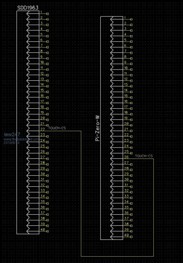 Board layout with ONLY the T_CS pin connected 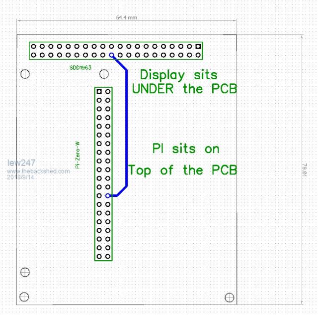 |
||||
| lew247 Guru Joined: 23/12/2015 Location: United KingdomPosts: 1709 |
Can anyone tell me exactly which wire/trace is in the wrong position please? Display sitting underneath the board, and the Pi-Zero-W sits on top of the board 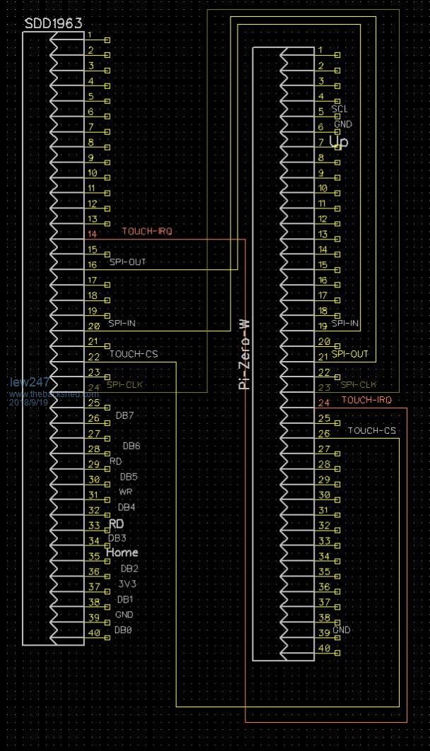 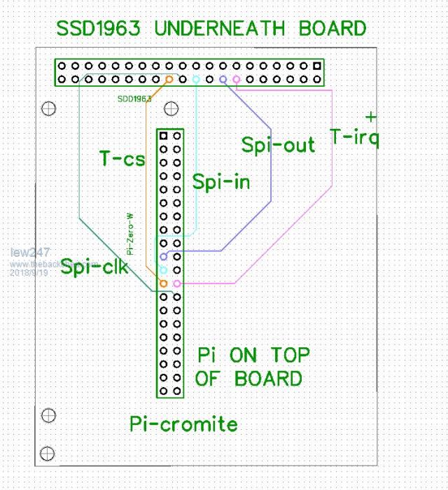 |
||||
disco4now Guru Joined: 18/12/2014 Location: AustraliaPosts: 1127 |
Hi Lewis, Seems OK to me. Have you tried unplugging everything and checking for shorts between the relevant adjacent pins, esp T_CS and T_IRQ to to anything else. Maybe also do OPTION LIST and double check the Touch is OPTION TOUCH 26,24 F4 H7FotSF4xGT |
||||
| Page 1 of 2 |
|||||
| The Back Shed's forum code is written, and hosted, in Australia. | © JAQ Software 2026 |
