
|
|
Forum Index : PCB Manufacturing : DIY PCB - Sources of Materials
| Author | Message | ||||
| Warpspeed Guru Joined: 09/08/2007 Location: AustraliaPosts: 4406 |
If you have a lot of DIP integrated circuits or multi pin 0.1" spaced header strips or connectors, one way to get the hole locations fairly accurate is to very solidly clamp a piece of Veroboard to your bare copper board very first thing, and use that as a drill template. If your board has four corner holes for eventual mounting, bolt the Verobard to your copper at the four corners so it cannot shift while drilling. Drill and de burr all the holes on your bare copper board first thing, before you lay out the tracks. Its then easy to precisely locate the artwork, or draw the tracks with the pen if the holes are already there. Cheers, �Tony. |
||||
TassyJim Guru Joined: 07/08/2011 Location: AustraliaPosts: 5886 |
That's the view from my "office", looking south. The view to the north from the lounge is much better. You can see the whisky plant on the next hill. When I used to do the etching methods, I made sure that I etched a small centre in the lands to work as a center punch hole for the drill.. When I worked for CSIRO, we had a 12000 rpm pedestal drill just for circuit boards. The CNC makes drilling "fun" Jim VK7JH MMedit MMBasic Help |
||||
| Andrew_G Guru Joined: 18/10/2016 Location: AustraliaPosts: 840 |
Jim - beaut view! I bet you get more done at night when you can't see the view. Re the 0.1" spacing - good ideas. Re the drilling, I use a Dremel (goes up to 35,000RPM) in its own little drill press. For the moment I'm only using HS drill bits so will need to address that shortly. If you look to the LHS of my PCB above the 2x 11 holes are where I need to solder an 11 pin female header on the wrong (Cu) side. I do this by using the headers with long pins and passing each pin through one hole and then back out through its pair - the pins are then soldered on the Cu side and the header actually sits on the Cu side too. I'm wondering if the Cu rivets referenced above achieve the same thing (saving 11 holes!)? Cheers, Andrew (PS have been off the www for most of the day) |
||||
| Tinker Guru Joined: 07/11/2007 Location: AustraliaPosts: 1904 |
Andrew, my hair stood on end when I read you are using HS drill bits at 35KRPM on fibreglass boards. I think that combination calls for  . .Those PCB drill kits on ebay are cheap, get a few as breakages might happen easily unless your drill press is rock steady. BTW, I used to drill at 3000RPM with the PCB drill bits, worked fine. Yes, that is my home built NIS26 yacht. She's located in Perth but plan to tow over to Hobart early next year for some cruising there. Klaus |
||||
| isochronic Guru Joined: 21/01/2012 Location: AustraliaPosts: 689 |
I did a few pcbs by hand and enjoyed the light/resist/etch processing, but drilling the holes was pretty tedious. Broke way too many drill bits...eventually used the broken-end bits in a dremel clone, to put a starter pit in each hole spot . Made it much better but still broke a lot. Gave up and sent them to pcbway, not as immediate but cheaper than buying the bits !! |
||||
| Andrew_G Guru Joined: 18/10/2016 Location: AustraliaPosts: 840 |
Hi Klaus, thanks for your concern. I don't run the drills at the max speed but at the lowest speed that they'll easily do the job (15 to 20k). The HS bits will dull quickly but I really am only doing small quantities. Andrew (Re cruising, I've done a bit, if you're wanting info on Victoria search on "CYAV Cruising Victoria" (I'm the guide's editor) - happy to answer any queries and pass on contacts. A) |
||||
bigmik Guru Joined: 20/06/2011 Location: AustraliaPosts: 2868 |
Hi Andrew, All, I found out the hard way to make sure that the pads you used had the holes for the drill hole.. The drill would then auto centre.. I vaguely remember trying vero to align the drill but gave up as I couldn�t attain the registration accuracy required, I also vaguely remember drilling a few holes in the wrong places.. I learnt that HSS drill bits were made of �glass� and broke every 20 or so holes.. especially when they started to get dull.. I graduated fairly quickly to tungsten carbide bits.. these were more fragile but lasted forever but the difference was they bit into the fibre glass so much better that I actually broke fewer bits. I used a hand held DICK SMITH ( I miss tricky dicky stores) drill I couldn�t afford a drill press.. and me starting life as a fitter and turner... tsk tsk tsk. I started with ferric chloride but it didn�t last long so I went for the cheaper ammonium persulphate which took longer to etch but could be reused more and you could tell by its colour when to toss it away.. I also ended with many pairs of jeans and tee shirts with acid burns or discolouration... Any way thanks for the trip down memory lane. @Andrew, glad you are using the Serial Backpacks.. Good luck all. Regards, Mick Mick's uMite Stuff can be found >>> HERE (Kindly hosted by Dontronics) <<< |
||||
| bigmik Guru Joined: 20/06/2011 Location: AustraliaPosts: 2868 |
Hi Jim, Is that the Lark distillery? I will probably be making a trip there next year.. expect a drunk or 3 to stagger into your back yard... Regards, Mick Mick's uMite Stuff can be found >>> HERE (Kindly hosted by Dontronics) <<< |
||||
| TassyJim Guru Joined: 07/08/2011 Location: AustraliaPosts: 5886 |
No. Lark is down south somewhere. My local is Hellyer Road. Their peated whiskey is a nice drop. It also does a good lunch and I would be honored to show you around. Geoff can confirm that the food is good.  It's not always that cold. That's Bass Strait in the distance. You can almost see the smog of Melbourne. Jim VK7JH MMedit MMBasic Help |
||||
| isochronic Guru Joined: 21/01/2012 Location: AustraliaPosts: 689 |
If you have an old xy plotter, I think the pen could be replaced with a blue led or small laser and it would "plot" on photoresist pcbs (?) - an experiment I never got to do .The small CNC machines are not bad now eg "T8" and so on, quite cheap with a bit of searching, and a fair bit of gcode creation software available |
||||
| bigmik Guru Joined: 20/06/2011 Location: AustraliaPosts: 2868 |
Lads, Back in the day, (hmm around 1985) Don had an hp 7675 (or similar number) plotter. We found some pens that worked well for a RESIST and we plotted some PCBs.. From memory they came out extremely good. I always loved watching the pens draw out the tracks.. Regards, Mick Mick's uMite Stuff can be found >>> HERE (Kindly hosted by Dontronics) <<< |
||||
| bigmik Guru Joined: 20/06/2011 Location: AustraliaPosts: 2868 |
@Jim, Hmm tempting... Lark is definitely on our itinerary, What area are you based? You never know, I would shout you a meal.. Regards, Mick Ps and of course a drink.. Mik Mick's uMite Stuff can be found >>> HERE (Kindly hosted by Dontronics) <<< |
||||
| Warpspeed Guru Joined: 09/08/2007 Location: AustraliaPosts: 4406 |
I did originally try using the PCB pens on my old XY plotter, it worked (sort of) but the pens need to be very new with a very sharp tip. Older pens tend to dry out and quickly develop a flat spot at the bottom, and will not draw with enough ink at the high writing speeds the plotter worked at. But a very high intensity blue LED with a small spot size is a very interesting idea. Just disable the pen lift solenoid and use the power to switch a rigidly mounted LED on and off. Cheers, �Tony. |
||||
| TassyJim Guru Joined: 07/08/2011 Location: AustraliaPosts: 5886 |
I've got a 'HP Draftmaster 1' plotter in the shed including a box of pens. Anyone looking at doing A0 sized boards? I think it cost me $10 at an auction a few years ago. That's the danger of going to an auction with a truck. Jim VK7JH MMedit MMBasic Help |
||||
plover Guru Joined: 18/04/2013 Location: AustraliaPosts: 302 |
Andrew_G I am trying to become familiar with AutoTrax DEX, experimenting with a number of different things. When I saw your layout that offered an opportunity to try and do a little bit of reverse layout, using guesswork and scaling etc I have almost finished by exercise when it occurred to me that I that it might be a simple exercise to add gerber files. I do not need boards manufactured but here is an offer. if you help specifiying what should actually go on the board, exact size, holes etc, then I will try and make it a finished board and you can have a set of gerber files and do with them whatever you like. When I am finished I will place the project here in the topic and hopefully we can get somebody that understand that manufacturing end of the system to help out. I am not much chop at that yet. As I needed components I have just taken what was nearest to fit the pattern. So if it is not a trade secret you will need to come up with some more details about the board. Even if you just want a pretty picture of your design, just fill in some more details of what you would like. I will post a 3D picture of the result. The holes in the board was my latest struggle to figure out, should have been dead easy but turned out not just like the manual said, I even had to read that. 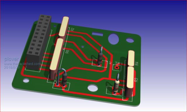 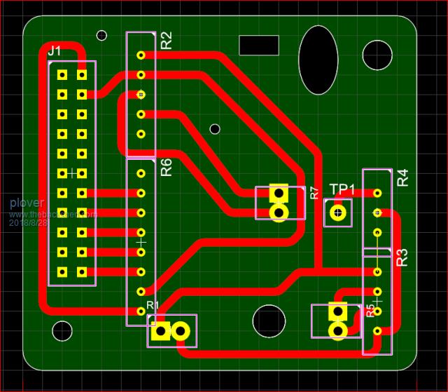 |
||||
| Andrew_G Guru Joined: 18/10/2016 Location: AustraliaPosts: 840 |
Hi Plover, good suggestion and I'm happy to help your testing (but I will probably use DIY PCBs for this current project, rather than gerbers to China) - but hey, I might learn something too... (this is the second time I've typed this as I hit the "Reset Form" instead of "Preview Post" button). The layout is still a moving feast but here is the latest from Diptrace: 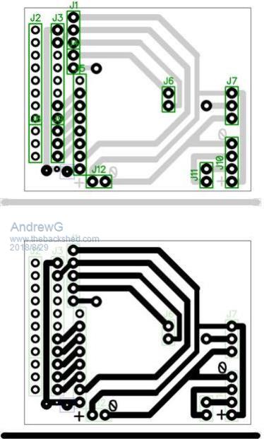 What I'm doing is interfacing Big Mick's "Serial Backpack" boards (here) onto a 1.8" 128x160 LCD display (I have 3 versions of this display - each pinout differs from Micks - I'll settle on one type, with the smallest footprint) and make say six boards. Here are the main features: J5, J6, the single pad between J6 and J7, J11 and J12 are all female headers to accept pins from BigMick's serial backpack, their spacing is important to match Mick's board. J2 and J8 are 11 holes through which the long pins of a female header (11 pins) on the Cu side of the board pass. The long pins are soldered to the pads on J3 and J9. The 11 pins on the LCD display are inserted into the female header J2/8. J1 and J4 (5-pins) are the connections to a female header for a HC-12 (lying flat on the top side, spring antenna to the right). J10 is a 90 degree male 4-pin indexed male console connection (Gnd, Rx, Tx, 5V) J7 is a 90 degree male 3-pin indexed connection to a DS18B20 (there is a built-in 4K7 resistor in Mick's board) (5V, data, Gnd). The pad to the right of J4 is in case I subsequently want a connection to pin 5 (Set) of the HC-12 (unlikely). The three pads below J9 are in case I want a resistor to reduce the voltage to the display (unlikely) - drill out the centre one to break the circuit, solder a resistor to the other two pads. The locations of J2/8 and J3/9 are important to fit the whole assembly, including the LCD, into the jiffy box and J1/4 need to be as far left as possible to accommodate the spring antenna in the box. If the holes in J3 and J9 were through plated then J2 & 8 could be omitted and the board shortened. The MM code is 90% done as I have a number of test modules (Veroboard) around the house (I'm happy to share it all but am not normally an exhibitionist . . .) Does this make sense? Cheers, Andrew |
||||
| plover Guru Joined: 18/04/2013 Location: AustraliaPosts: 302 |
Rather a surprise, I have some parts to make one backpack also from bigmik, perhaps I will be more interested in the your boards than I expected. Still waiting to be put together with a display. I have not yet checked if there will be a problem with interfacing. Now I have better get it checked out. I think I recall my idea was to get the correct display and I think I ordered 3 but not if one of those was for bigmik version. I know the feeling with loosing a big post just when it is ready to go. As soon as I get a spare moment, I will revise with the details you have given and be back. |
||||
| Boppa Guru Joined: 08/11/2016 Location: AustraliaPosts: 814 |
One trick I learned a while back is for long explanation posts, I write them in libre here (ubuntu) or notepad on windows and then copy/paste into the post reply window, lost too many long posts (not so much here, altho I lost one) but wordpress in particular loses long posts regularly. Another (not always successful) successful way is just before hitting reply, copy the entire post, so if it gets lost you can repaste it into a new reply window |
||||
| Andrew_G Guru Joined: 18/10/2016 Location: AustraliaPosts: 840 |
Thanks Boppa, good tricks! I had composed the bulk of it in Notepad but lost the nuances and spelling corrections etc. I hadn't been backing up posts as I went but it is a good practice. I'm about to suggest moving the button to the far right (not being political in our current environment . . .) Andrew |
||||
| plover Guru Joined: 18/04/2013 Location: AustraliaPosts: 302 |
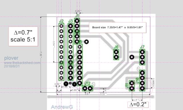 Andrew_G Been looking at the dimensions of the board, working backwards from scaled version for the fun. Your picture is actually on the schematic page in my system and I have placed 'guide lines' then from knowing a few unit points like the headers a 8 way header 0.7" and where I have a circle another check point. Happens that the sale must be close to 5:1, however what size is your boards actually. One more question, J2 and J3 are 8 way headers with a 3 way header added? What are the names? I probably should be able to figure it from the description, but will cheat and ask? The old brain cells are rebelling a bit doing over time.  |
||||
