
|
|
Forum Index : Microcontroller and PC projects : STEP Command
| Page 1 of 2 |
|||||
| Author | Message | ||||
| Geoffg Guru Joined: 06/06/2011 Location: AustraliaPosts: 3165 |
After the long running thread PWM Gaps I have learnt a lot about the PIC32 hardware involved in creating a stream of pulses (timers and output compare) and I believe that they could be made to drive a stepper motor while counting each step. I know very little about the practical side of using a stepper so I thought it worth floating the idea here for comment by some of the stepper experts. I thought that the command could be somewhat like this: STEP chan, accel, speed [, steps [, int]] Where: chan = the channel (pins labelled PWM 1A or 2A) accel = the acceleration or the ramp up/down rate speed = the top speed (after the ramp up) in steps/sec steps = the total number of steps to be made (incl ramp up/down) int = an optional interrupt sub to call when the steps have been completed The command would run in the background. If you left off the last two arguments the stepper would ramp up to speed then keep running until another command specified a different speed. If the full command was used the stepper would ramp up, run and ramp down to zero with the whole operation using the exact number of steps specified (and then the interrupt sub would be called). Does this sound useful? Any other features/options that it should have? Would it be useful to have steps/speed pairs so that it could run at one speed for a certain number of steps, then another speed for more steps, etc? The other question is how should the acceleration be specified? I was thinking of a certain percentage speed increase per step. But that would be exponential and I understand that steppers loose torque at higher speeds so maybe that would not work. Any other suggestions? I will not have time to implement this before I head off overseas but it would give me something to think about during the long flight. Geoff Geoff Graham - http://geoffg.net |
||||
TassyJim Guru Joined: 07/08/2011 Location: AustraliaPosts: 5878 |
Are you taking the direct Perth-Heathrow 17 hour flight? That's a lot of thinking time. I find the 14 hours Melbourne to Dubai as much as I can (just about) handle. Jim VK7JH MMedit MMBasic Help |
||||
| MicroBlocks Guru Joined: 12/05/2012 Location: ThailandPosts: 2209 |
You will be getting in a pretty difficult territory. Steppers are normally used together with a gcode interpreter that can have separate ramp up/down curves. These are not always linear. Lots of gcode interpreters allow for defining a curve by setting points on a graph (time/speed) Once two steppers (or more !!) are involved then things get very complicated indeed. For just a single stepper I would suggest having at least different accelerations before reaching and maintaining max speed. The first acceleration is to overcome the initial force needed to get the mass moving, once it moves acceleration can get higher. Compare it with a large truck with gears. 1st gear is to just get the truck rolling, 2nd gear is to get up to speed. More gears, more fine control to reach top speed. Slowing down is the same but in reverse. This would then need an extra parameter. STEP chan, initaccel, accel, speed [, steps [, int]] or if you want more fine control (i think this would be ideal) STEP chan, accelArray, speed [, steps [, int]] More fine control will allow to compensate for resonance as each motor and assembly will have its own particular set of best acceleration values. This comes from experience with multiple 3d printers, CNC routers and lasercutters which all had their own little weird configurations to get rid of resonances and missing steps. Once you need to move two motors at the same time a lot of calculations are needed to get them to move smoothly. Very difficult to get this right. In cases this is needed a GRBL board add-on is a much easier solution. Microblocks. Build with logic. |
||||
| Malibu Senior Member Joined: 07/07/2018 Location: AustraliaPosts: 145 |
Hi Geoff, glad to see I've got the brain cells moving after our epic debug session!  I for one think it's a great idea - hard to do? I'm not sure, but probably a good function to try and implement. First up, here's a couple of stepper descriptions from the people that know a lot about them, Gecko Drives - Stepper Motor Basics & Microstepping Explanation I run 6 Gecko's around my workshop on various CNC's and are well worth the cost. Before I get too deep into my reply, your diligence in debugging in what I've done so far on my project, puts the smooth control of my single stepper up with the smooth control of the Gecko. I'm more than happy with the way it's driving now. Having said that, if you're looking to do a specific function to driver steppers, as MB says, there could be a few pitfalls in the hardware side of things. I for one don't think it will be an issue for code, because in the end it's up to the coder and designer to ensure that acceleration, magnetic resonance, coil currents etc are taken into account. For me, it was as simple as sending pulse out by using the PWM and adjusting the rate of increase to keep step stall in check. Probably a good starting point, but I think you would also need to incorporate a ramp down (remember, stop the pulses to a stepper and the motor stops dead in its tracks) Here's a scenario: A camera dolly that could be used for miniatures on a film production (hey, I'm making this up as I go!) You have a $10k camera mounted on a stepper controlled dolly, so you want to be pretty gentle. By your code, I would do something like STEP, 1, 5, 2000, 10000, CameraOff Step: Call the function 1: Channel Number 5: Seconds to reach full speed 2000: Step speed (2000 at 200PPR is 600RPM) 10000: Steps to travel CameraOff: the interrupt to call If at the end of the travel and you just turn off the stepper, your $10k camera will stop dead and maybe get damaged. So maybe you need a Ramp Down setting as well (or maybe even a completely different function for ramping down) Keep in mind, I'm just rambling my thoughts at the moment, so feel free to pick nits out of them  A good question! I don't think there's a 'standard' on how it should/could be done. Some will want over time, some will want in revs... each will be different and will depend on each application. My code used the FOR:NEXT loop (as you know) and I used a step value for fast or slow ramp times. That actually increases the Hz Value in 'blocks' and you start to get away from a smooth speed increase. Because I'm running 1/32 step mode (200PPR*32 is 6400PPR) it's not really a problem....... which brings another point, stepping at full step, and stepping at microsteping rates are 2 completely different beasts and maybe you could have another setting for microstep mode? I'll stop rambling now! Hopefully there's a bit more for you to ponder on the flight John |
||||
| KeepIS Guru Joined: 13/10/2014 Location: AustraliaPosts: 1345 |
I suppose it depends on where this is aimed, I assumed it's not aimed at serious CNC coders running gcode and the like? AFAIKT that is already a mature market and well catered for. For those of us using steppers for different experimental designs and having a blast with the ease of experimenting using an MM, I think this has a lot of merit. Again, I'm driving 3 stepper motors with the MM.Plus, two are in parallel because of what is commonly referred to as a gantry (I think) this is quite long in my case and needs control / drive at each end, these two are running concurrently with the 3rd stepper and each moving to a position that is at the limit of accuracy of the Digital Scale slides that the MM.Plus is decoding, all this while varying the PWM drive frequency according to position data and simultaneously moving each axis to the requested position. The only limitation of accuracy is the mechanical design and the Digital Scale slide, in this case 0.02 mm over its length. What I don't quite understand is why there is a big issue when using the MM to drive stepper motors if you are using a digital DSP stepper drive controller, I don't have any issues on the MM-Plus and the DSP controller has anti-resonance anti-everything built in, especially when a really good controller is only $50. However I do understand that other designs rely on counting every step, either with a feedback encoder or simply by the number of pulses sent, in these cases I do understand why PWM is a problem. I ramp up / down and micro step using PWM and a digital driver, never had a problem in a closed loop system, I had to use PWM as the MM.Plus cannot clock and decode dual high speed positional data AND control dual pulse trains to drive the controllers any other way, buy it runs brilliantly and is 100% accurate. What I trying to say is, it depends on what you use it for, and for a lot of experimenters what Geoff is suggesting would be quite handy. But again that's just my humble opinion. It's all too hard. Mike. |
||||
| matherp Guru Joined: 11/12/2012 Location: United KingdomPosts: 8566 |
I thought about this as well after the original thread. My version was STEP pinno, start-speed(PPS), end-speed(PPS), acceleration(PPS/S), N, Pulse_width(uS) PPS = pulses per second PPS/S = pulses per second per second Given this you could program the equivalent of Mach3 which is the most common CNC program. i.e. you could do everything you might need. N could be set to zero for continuous output but that would never be used if position was important. the BIG requirement though is for command stacking. It must be possible to send the next command whilst one is running and have it immediately actioned as the first completes. A stack of say 20 commands would be required to achieve continuous accurate motion. To understand this think of something as simple as moving the stepper half a turn from stationary to stationary. It requires a minimum of two commands and there can't be a pause between them. AND of course it must be possible to run commands on more than one pin at the same time - 4 would be optimum |
||||
| Geoffg Guru Joined: 06/06/2011 Location: AustraliaPosts: 3165 |
Thanks for the feedback. For a start, I was just thinking of simple uses for steppers (for example, a coil winder, simple robot, etc). I agree that high powered, high speed steppers on something like a CNC machine are too much for the simple Micromite and would be better handled by controllers designed for the task. Maybe I should have used the term accel-decel for the second argument. I was planning to use this number for both the acceleration up to speed and the deceleration back to zero. So no dead stops. Interesting comments Peter. I was thinking that most stepper applications would start from zero speed and move a number of steps returning to zero speed. Is this wrong? I like your idea of stacking. Then the command could be simpler, like: STEP chan, accel-delec, speed, steps, speed This assumes that the stepper is already in some state (stationary or moving) and this just adds a new sequence for when the previous sequence terminates. There would need to be a function for getting the status (what stage, what speed, etc). Perhaps I have misunderstood but I thought that my original suggestion would do that. For example: STEP ch, accel-decel, 12000, 100 Would make a standard stepper (200 steps/rotation) start from zero, accelerate to 60 rpm then decelerate and stop at exactly half a turn (100 steps). The maximum would be two simultaneous SERVO outputs. This is because there are only two timers free for this sort of thing. BTW I was going to use timer interrupts to count the steps so there could be a performance issue with two servos running at high speeds. I thought that simple stepper applications used a controller like this (pololu.com/product/2128 ) and that microsteps were handled by the controller - all the Micromite had to do was pulse an output pin for a certain count at a certain speed. Am I wrong again? I'm going Perth->Bangkok -> Frankfurt -> Dublin... 24 1/2 hours... Aaaggghhh. Fortunately the longest leg is only 11 hours. I have done Sydney -> San Francisco a few times and at 14 to 15 hours that is bad enough. Geoff Graham - http://geoffg.net |
||||
| robert.rozee Guru Joined: 31/12/2012 Location: New ZealandPosts: 2285 |
not wanting to pour cold water on the idea, but... it seems to me that the improved implementation of the PWM command provides an excellent building-block for those wanting to experiment with stepper motors. within the mechanical limitations of the stepper being used, one can, using BASIC code, implement all sorts of ramp-up and ramp-down profiles, along with other complex behaviour. while a dedicated STEPPER command may reduce this to a single line of code for some subset of applications, no matter how generic (and hence complicated) the implementation of the command is, there will still be many applications for which it is not well suited - resulting to the user falling back to using PWM with a timer interrupt and couple of arrays of speed values to create the desired ramp profiles. looking at it from another angle: is there anything the STEPPER command could do that could not be accomplished equally well using PWM along with the existing mmbasic functionality? if the answer is 'no' then the addition would violate one of your long-standing tenets for mmbasic. now having said this, for the likes of the MX470 and above there is plenty of spare flash, and no one is disadvantaged by the addition of a STEPPER command (they can simply elect to not use it). the only problem i can see here is that the new command is unlikely to be able to be shoehorned into the small quantity of spare flash on the MX170, which may see a further divergence created between the two branches (MM2 and MM+). folks may produce projects that use the STEPPER on an MX470, that will require recoding for the MX170. this may or may not be a concern. cheers, rob :-) |
||||
| MicroBlocks Guru Joined: 12/05/2012 Location: ThailandPosts: 2209 |
BASIC is too slow for implementing ramp-up ramp-down profiles. The steppers would just stutter and sputter. For this you need exact timing and high speed, only achievable from C. Microblocks. Build with logic. |
||||
| Geoffg Guru Joined: 06/06/2011 Location: AustraliaPosts: 3165 |
Rob, the big feature of implementing the command using the PIC32 hardware is that it would be able to accurately count steps and therefore step to a precise location (even at high speeds). Geoff Graham - http://geoffg.net |
||||
| matherp Guru Joined: 11/12/2012 Location: United KingdomPosts: 8566 |
Yes it would - poor example on my part - this is a special case but in many instances you may want to accelerate to a particular speed, then to a second speed, then slow.... etc. In my ponderings I was thinking of using a single timer for all outputs. The interrupt would be set at the time of the next event to be scheduled. i.e. the various outputs would be merged into a single sequential set of time/pin-event pairs. The timer would be running at maximum clock speed and pseudo events used to re-trigger the interrupt if time delays > 2^16 clocks are needed Absolutely correct. Also the pulse duration is very short and it is probably OK to handle both the pulse on and off in the same interrupt routine with a uSEC() command |
||||
| robert.rozee Guru Joined: 31/12/2012 Location: New ZealandPosts: 2285 |
good point - i hadn't thought of it as a simple positioning command, my mind was stuck on coil winding. i could see a few useful applications :-) do you think it would be able to fit into the available flash on the MX170? or would it need to be a C-function? cheers, rob :-) |
||||
| geeken Newbie Joined: 13/01/2018 Location: United StatesPosts: 20 |
Geoff A very useful addition to the 'Mite! As tricky as Steppers can get, many basic installs & educational projects would benefit from this addition. And something can be up & running fairly simply. Somehow include a warning that it won't necessarily work, due to the physics of the resulting rig - - - a disclaimer clause is recommended :) Would suggest basing the concept on the Toshiba based Stepper "Driver Amps", all available on eBay from numerous suppliers. Their interface is opto-based (viz. EMC & isolation) and seems very standard. Search on eBay with keyword "TB6600". The 4 Amp ones are about $10 & the 5 Amp one (better) is about $16 (typical part # = HY-DIV268N-5A). The reason I mention them is that these Toshiba-based Amps are switched in a particular way which dictates how to arrange for the 'Mite to drive them, from firmware. These are PWM based, however, they take an approx., fixed 50 uSec pulse combined with a certain time interval - doesn't matter exactly when so this can make the firmware easier to setup. The closer these fixed pulses are together the faster the motor goes = simple. Regarding the commands - suggest that these could be available in two flavors : 1) Intended next shaft speed (in steps / sec), time to get there, plus details, OR 2) Intended next destination in #'s of steps, with time to do them, plus details. This two command solution covers for those developers who want to think in terms of speed in addition to those who want to think in terms of position. Or either, which is also necessary as an option. Using Time as one of the input variables is relevant 'cos this field deals with Load Inertias & Power requirements. The Command "details" include ; - Direction ?, - Disable at this end of this command or lock the motor at the end of this command ("Enable")? , - Run to a sensor pin-change, on Pin # ? - Which Sensor polarity-change checked for on this Pin, next ? (this can change regularly). - etc, etc. The Options command related to these Stepper Commands would handle circuit dependencies. Also the Options command is about setting any missing-command-part defaults such as "direction". If a Command detail is left off, it defaults to what ? Suggested Stepper-Option topics (i.e., in the Background); - How many Output functions are to be used ? (1, 2, or 3, at this time - i.e., from the list Step, Direction & Enable - see below). - Output polarity for each output pin (circuit dependent), - How long the fixed Pulse should be (probably 50 uSec or above = 10 KHz max. step rate). - Shutdown timeout (like a watchdog), where "0" means "Never". - Sensor input Pin #'s taken over for the stepper input-sensor circuits. "0" means no sensors used. There could be numerous sensors needed - - - - Default Polarity of the position Sensor inputs. (Some position sensors are high-side (PNP) and some are low-side (NPN) oriented). Suggest that the sensor inputs are level based - easier for a user who is learning and for simple setups. If edge-based is also required then an Interrupt arrangement could be added with a different Command called "POS_SENSE", or similar. What happens between these commands, what / when is the next command and how does it end - these issues are very much left up to the programmer! (Come back in 3 days and the motor is still faithfully running or stalled - oh well - - -). With the TB6600 based Amps, typically, no signal is required to Enable it. Driving the Enable Optocoupler will shut the unit down (i.e. stops currents flowing to the Stepper). When Enabled, the Stepper is electrically "locked", and can be stepped under Power. Minimally two 'Mite o/p's are needed, Step & Direction. (A third would be Enable as just mentioned). A circuit using just a Step pin is a possibility, particularly for educational projects. "Step" & "Enable" only is also a popular combination. Some sort of Transistor / FET should be placed between between the 'Mite output pins and the TB6600 Optocoupler inputs. Sensor inputs circuits should be isolated, which Optocouplers are good for. Regarding how this relates to all of the other Stepper Driver-Amps available, looking to further comments about experiences with different chipsets. * * |
||||
| Paul_L Guru Joined: 03/03/2016 Location: United StatesPosts: 769 |
Good grief! The Bangkok -> Frankfurt great circle leg is 5000 miles and it requires overflying Myanmar, Bangladesh, Nepal, Tibet, Tajikistan, Uzbekistan, Kazakhstan, Russia, Ukraine, Poland and Germany! Pan Am flew that route, but with stops at New Delhi, Dubai, Tel Aviv, Istanbul, Belgrade, Vienna, and Frankfurt for a distance of 6400 miles, but it avoided overflying places that didn't have ground control protocols to handle commercial aircraft. I know that commercial routes have gotten a lot more direct in the last 25 years, but I really don't know how they would route that leg, even today! Better you than me. I hope you have a seat with some leg room! I guess the stepper motor drive problem will give you something to think about during the flight. As long as the moving mass is small I don't think there will be too much trouble absorbing feedback reflections generated by the inertia of the rotor. I suspect that using something like the Pololu dedicated controller would be the easy way to solve the acceleration / deceleration and physical feedback problems. Have a good vacation in Ireland! At least everyone will be driving on the wrong side of the road on both ends of your trip. I just wonder if you'll be able to converse with them. I never asked you if you had trouble driving on the right side of the road last year in the states. Paul in NY |
||||
| Malibu Senior Member Joined: 07/07/2018 Location: AustraliaPosts: 145 |
Wow, lots of good comments when I got up this morning! No, you're exactly right. That board is the pin-for-pin equivalent of the board I'm using (the 8825). I just meant that maybe have a microstep value that can be added to the command line to automatically calculate the 'new' frequency value during a microstep value change. Thinking about it later, it's probably not worth the effort for the perceived value, so scrap that idea I would say your absolutely correct. Any motor does the same thing - Start at 0, run for a time and stop at zero so in that sense, a stepper is no different to all other motors. I was pondering the problem last night and wondered if instead of looking at it from a dedicated stepper problem, maybe it only needs a variable frequency function. Steppers that most will drive are going to be the 'step/direction' style, so settings like DIR, ENABLE, MODE can easily be handled by separate pins on the MM. The only concern would be the frequency. On that basis, maybe something like FREQOUT Hz, Time, Count would be enough? FREQOUT : Call to the function Hz : The required final frequency (The idea being that the function already knows what frequency it's generating. If the new Hz is higher, ramp up... if it's lower, ramp down. If it's a first call to the function, then it would start at the minimum frequency setting and ramp to the set Hz. The motor would be starting from a zero value) Time : The time value to ramp from the old frequency to the new Count : A readable value that can be used to compare to in code and use for positioning (or anything really) EDIT: Sorry, I didn't really explain the COUNT very well... This would be a value that's updated by the function itself. It could hold the total number of pulses that have been sent out. If in a standard 200PPR setup, when COUNT has a value of 200, you know it's done 1 rev, 400/2 revs... and so on  A quick example code that I can see being a real world use: FREQOUT 200, 500, Position '<<-- Call function, set 60RPM, 1/2 second ramp, position variable Do while Position < 10000 '<<-- If it hasn't reached the position If Position = 300 then Pin(50)=1 '<<-- trun on something at a certain point loop '<<-- reached the end yet? PIN(50)=0 '<<-- Turn off something before the final position FREQOUT 20, 500, Position '<<- Ramp down from current Hz to the new Hz If Position = 10200 Then FREQOUT STOP '<<-- End of the travel, stop the frequency output The COUNT variable could be used for lots of applications - Linear encoder feedback, rotary encoders and speed control pots by a continual compare using interrupts, or a compare when the final position is reached. Just a few more ideas to muddy the waters! John |
||||
| TassyJim Guru Joined: 07/08/2011 Location: AustraliaPosts: 5878 |
These boards are cheap and readily available. They use the TB6560 chip. Driving one with the micromite would make a great base for robotics experiments. 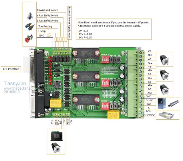  My next flight is Devonport-Melbourne-Dubai-Copenhagen. 31 1/3 hours or about 36 hours home to hotel. It will be my last long-haul trip. Only 269 days to go... Jim VK7JH MMedit MMBasic Help |
||||
| geeken Newbie Joined: 13/01/2018 Location: United StatesPosts: 20 |
|
||||
| geeken Newbie Joined: 13/01/2018 Location: United StatesPosts: 20 |
Jim : The boards that you show use the chipset thats in the Toshiba family I mentioned in my earlier post - I like the board u posted because it has 3 circuits - useful ! (X, Y & Z axes). All : Addition to my earlier post : The second type of command needed is a position-based movement command. That command needs more sections than the speed command. This is possibly how it could look ; Intended next destination in #'s of steps, the time to do them, plus accel ramp, plus decel ramp, plus details. so thats : STEPCOUNT, MOVETIME, ACCELRAMP, DECELRAMP, plus details as I posted earlier. The 'Mite can calculate a movement pattern from this type of info. There may be more to it ! These are starting-point suggestions for Geoff to get some 'Mite Code planned out - lets get him as much feedback as we can about stepper systems. Ken |
||||
Azure Guru Joined: 09/11/2017 Location: AustraliaPosts: 446 |
Not to take away from all the good suggestions, keep them coming. I think Geoff's intention is a basic stepper motor control primitive that is simple but as versatile as possible. Almost all of the suggestions made that are higher level stepper control would be possible in the users code using the primitive together with their own movement and feedback control subroutines. Some more complex and critical timing may require CFuntions to implement. My 2c worth: I like the concept suggested that the primitive can be chained together to make more complex moves. Depending on implementation method, there would need to be a way to cancel the moves in case of some emergency trigger (eg limit or safety switch activated). The ramp up and down would need to also support no ramp (0) for either or both to be able to chain primitives together. The primitive should keep track of its current speed and that is the starting point for the next speed together with any specified ramp up or down. The idea of specifying the step count sounds very useful. The ability to be able to read the current speed and step count would both be very useful. The user program would need to keep track of absolute position as the primitive is not likely to control direction (without starting to get complicated to cover contingencies). Have a great trip Geoff. |
||||
| PeterB Guru Joined: 05/02/2015 Location: AustraliaPosts: 639 |
G'Day all On the subject of ramps. I use KCAM with a 3040 CNC machine to mill boards and it works a treat. With KCAM you can turn the ramp on or off and, if on, it can be set to x Hz/step i.e. linear and also there is a RAMP START setting in IPM which is the speed at which the ramp starts. I have no idea what that does. I had a look at LINUX CNC but I don't think that is in English. I also use a special Grogster designed board to drive steppers more as a variable speed synchronous motor than as a true stepper. Speed is determined by ground speed via GPS so motor speed is adjusted every second. The maximum frequency is about 3kHz, 60 RPM. Starting has never been a problem but a start ramp would make me very happy. Peter |
||||
| Page 1 of 2 |
|||||
