
|
|
Forum Index : Microcontroller and PC projects : Explore-64 version 1D....
| Page 1 of 4 |
|||||
| Author | Message | ||||
Grogster Admin Group Joined: 31/12/2012 Location: New ZealandPosts: 9975 |
Hi all.  I am working on a new version of the E64, to include the 1455 USB interface for serial and programming a new HEX file. There are a couple of reasons for my doing this: (1) The original E64 was designed before the sexy 1455 USB interface chip became the new standard for USB connections to MicroMites, (2) I have wanted and needed the 1455 on the E64 myself more then once, and (3) the current thread about the bricked E64 has yet again highlighted the problem with the PIC32 USB connection. The new version will be "1D" and will bring the E64 unit into line with the E28 and E100, which both now offer the 1455 USB interface. Needless to say, Peter's MMX's all use the 1455 chip also, so the E64 is really the only odd-one out in the family of MicroMites now, to suffer from lack of this chip. The only problem is that this has forced me to move the board to four-layer so that I can get all the tracks in that are needed - especially once you factor in the 1455 chip. The PCB will remain exactly the same size as the current E64's, and will be pin-for-pin compatible, meaning you can just swap an older one for a newer one, if you want a USB connection that actually works...... Passives will move to 0805 rather then 1206 as they are right now, to give me a few more mm of routing room. SOT-223 regulator will change to SOT-89 footprint, but remains the exact same MCP1703-33 device. Again, this just gives a few more mm for routing tracks. The new boards will be blue in colour rather then the stock green, just to be a little different, and to easily distinguish the E64's with the 1455 USB interface, from all the other older models without it - 1A's, 1B's and 1C's.(they are ALL green). The "Explore-64" name and concept remain the property of Geoff at all times. Smoke makes things work. When the smoke gets out, it stops! |
||||
| WhiteWizzard Guru Joined: 05/04/2013 Location: United KingdomPosts: 2991 |
Hi G, The addition of a 1455 to the E64 would be fantastic  My only worry with your above post is the mention of 4-layer - as you know, this has a cost impact. I am not sitting in front of an existing E64 currently, but I was hoping there was enough 'track-space' for this to be implemented on two layers. Still planning the same concept for the 44-pin module too (to replace the current onboard FTDI chip). Spoke to Geoff a long time ago about this, and then naming this the E44. This then gives a full 'line-up' of MM Explores: 28pin to 100pin. Off to go and look at one of your E64 PCBs now . . . WW |
||||
Azure Guru Joined: 09/11/2017 Location: AustraliaPosts: 446 |
Great move Grogster, will that be an MM+64 or MM+64 Backpack? |
||||
| WhiteWizzard Guru Joined: 05/04/2013 Location: United KingdomPosts: 2991 |
Azure, The MM+64 BackPack is a Silicon Chip (Nicholas Vinen) design. Grogster is referring only to the 'Slim' E64 module. |
||||
| matherp Guru Joined: 11/12/2012 Location: United KingdomPosts: 11499 |
Why not change the form factor slightly? I did this version for the 64-pin MMX and easily routed it using 1206 parts on 2 layers |
||||
| Grogster Admin Group Joined: 31/12/2012 Location: New ZealandPosts: 9975 |
Yes, I am. I hear you on the PCB being 4-layer but there just is no room left. Remember there are all the 1455 tracks, and various grounds and supply rail tracks - all to get into two layers. It was quite a struggle to get the E64 into two layer as-is. The E100 and the E28 are also four layer for the same reason. The E28 is small, though, so that keeps it's PCB cost down. A quick check on the PCB GOGO website calculator shows that for small quantities(10 or so, not in a panel), the boards would cost about US$7 each INCLUDING a share of the DHL shipping cost, so that's not bad I don't think. I see the 1D's perhaps pushing the price up by about $5 or so, when you factor in the extra parts and 1455 chip, and the new PCB. I don't think it's TOO scary.....  @ matherp: That is always an option, but I need to keep the E64 the exact same size cos I want to use the new ones with the 1455, on existing motherboards designed to accept an E64 module. If I change the PCB size, i'm stuffed!  Smoke makes things work. When the smoke gets out, it stops! |
||||
| WhiteWizzard Guru Joined: 05/04/2013 Location: United KingdomPosts: 2991 |
Radical thought/idea: Modify the existing 2-layer E64 to have something like an 7-way connecter. Then into this plug in a 'miniature' MicroBridge (mMB) module. A 2x4 on a 0.1" spacing would suffice - but smaller pitch would be better? The idea behind this is that the E64 can be just an E64 (without mMB module plugged in); OR it can have the mMB 'permanently' plugged in to achieve what you're proposing in your OP. Keeps costs down, and would be a useful way forward - especially for those wanting to keep current consumption down. So the standard ICSP connector becomes a new 'mMB' connector. Does this make sense? |
||||
| Grogster Admin Group Joined: 31/12/2012 Location: New ZealandPosts: 9975 |
Yes, it does. Nice thinking. Very clever. I will look into that idea. EDIT: I still prefer everything on one board, but that is an idea too clever NOT to look into. Smoke makes things work. When the smoke gets out, it stops! |
||||
| WhiteWizzard Guru Joined: 05/04/2013 Location: United KingdomPosts: 2991 |
mMB would just need a button and LED on top side, and PIC + resistor/cap on underside. Just need a robust (and tiny) connector. Needs these 7 signals: 0v, 3v3, Rx, Tx, PGD, PGC, MCLR If a 'miniature. module could be made then all future MM module designs could include a space on the PCB (and a connector off course) for this. No need for a USB socket as the MM module is often powered via a USB (don't want to end up with 2 USB sockets in a design). So how small could a mMB be?? |
||||
| Grogster Admin Group Joined: 31/12/2012 Location: New ZealandPosts: 9975 |
Why don't we go down to die-level, and have the PIC32 and 1455 along with all passives on the same chip!!!!!!  Smoke makes things work. When the smoke gets out, it stops! |
||||
| Grogster Admin Group Joined: 31/12/2012 Location: New ZealandPosts: 9975 |
Well, WW might have had something there.....  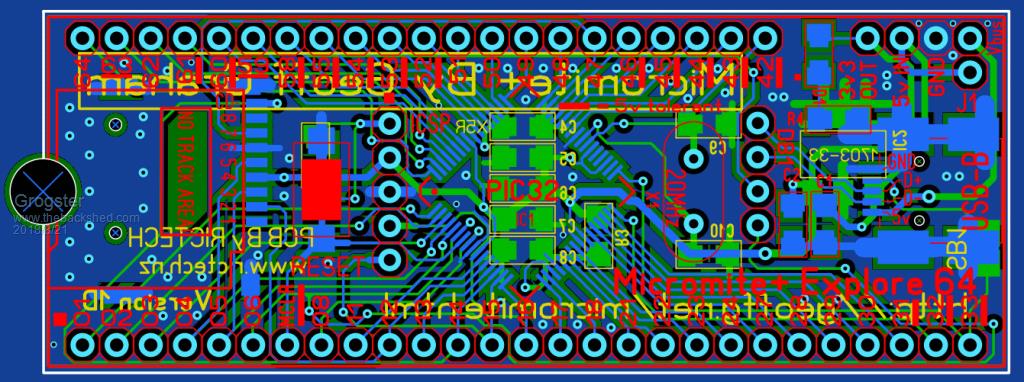 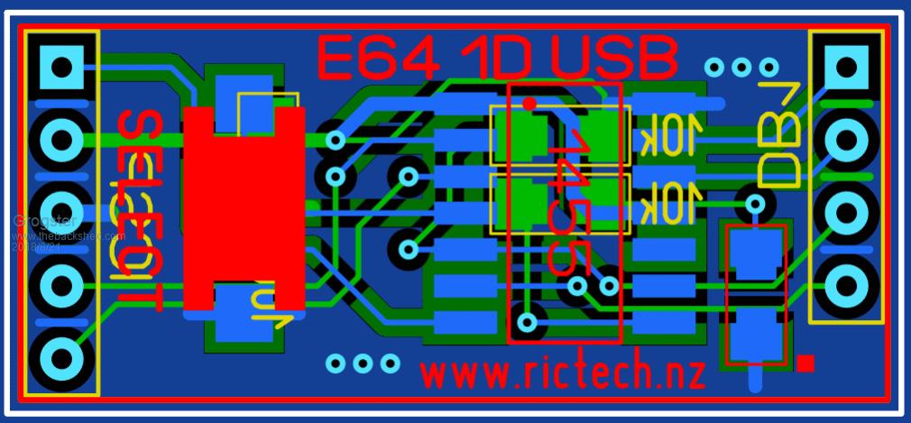 First image is of the modified E64, still two-layer. Bottom image is of a small daughter-board that plugs into the the pin-headers on the E64, to provide all the 1455 features. Naturally, the E64's USB socket has now been routed to the daughter-board, and is no longer connected to the PIC32 chip. Daughter-board size is 31mm x 14mm, so quite small. 1455 chip is standard SOIC. All passives are still 1206 size on both the E64 and the daughter-board. The 1455 daughter-board plugs into the two pin-headers on the E64. One of them is the existing ICSP header, and the other one is just to the left of the USB socket. The board is self-supporting on the pin-headers. Smoke makes things work. When the smoke gets out, it stops! |
||||
TassyJim Guru Joined: 07/08/2011 Location: AustraliaPosts: 6538 |
Looking good Grogster. I reckon I could retrofit one of the daughter boards to my 1B board. The USB data lines are get-at-able on the 1B, even for me. I assume the other two pins at the front go to the console pins. Jim VK7JH MMedit |
||||
| Grogster Admin Group Joined: 31/12/2012 Location: New ZealandPosts: 9975 |
You assume correct. Smoke makes things work. When the smoke gets out, it stops! |
||||
| WhiteWizzard Guru Joined: 05/04/2013 Location: United KingdomPosts: 2991 |
Hi G, This looks good. So the E64 can be powered via the 'existing' E64 USB socket. And then when you want Comms and/or Firmware update you just need to insert the daughterboard (and fire up TT or PIC32PROG). Is that correct? Would be great to test this out to see how it 'feels' in operation. Then if its ok (and after any 'tweaking') this could possibly be a standard 'comms/programming' module used for any future MM board designs. Great work G . . . |
||||
| Grogster Admin Group Joined: 31/12/2012 Location: New ZealandPosts: 9975 |
Hey there WW. Yes, if you install the daughter-board, you will get the 1455 USB serial connection, and it's HEX programming features. Without the daughter-board, the E64's USB socket becomes a power-only connector. This will totally avoid all the problems with the E64's current PIC32/Microchip USB connection problems when users press the E64's RESET button.(which causes Bill to drop the VCP) Smoke makes things work. When the smoke gets out, it stops! |
||||
| TassyJim Guru Joined: 07/08/2011 Location: AustraliaPosts: 6538 |
If you were really adventurous, you could put three solder bridges for the 3 traces you removed to pins 34, 36 and 37 so that any masochists out there could still use the old USB. Why anyone would want to, I am not sure. Jim VK7JH MMedit |
||||
| Grogster Admin Group Joined: 31/12/2012 Location: New ZealandPosts: 9975 |
Why not. There is space there for some very small pads now. As you say, weather anyone would ever use them.... Smoke makes things work. When the smoke gets out, it stops! |
||||
| robert.rozee Guru Joined: 31/12/2012 Location: New ZealandPosts: 2528 |
quick question: with the necessary firmware changes, would it be (or is it currently) possible to use the existing USB connector in host mode to connect a USB keyboard? i'm also thinking along the lines of peter mather's idea of a wider PCB, that then has two USB sockets - one for console/programming/power that runs to a 1455 and 3v3 regulator, and a second one that is for plugging in an accessory keyboard and that can NOT be used for powering the E-64. power for the second socket could come from the first via a simple diode. see this for an idea of the PCB sizing: https://www.olimex.com/Products/Duino/PIC32/PIC32-RETROBSD/open-source-hardware any idea on how many E-64 boards are currently in service, and how many designs would be thwarted by moving to a wider footprint? cheers, rob :-) |
||||
| Grogster Admin Group Joined: 31/12/2012 Location: New ZealandPosts: 9975 |
Here you are, Jim: 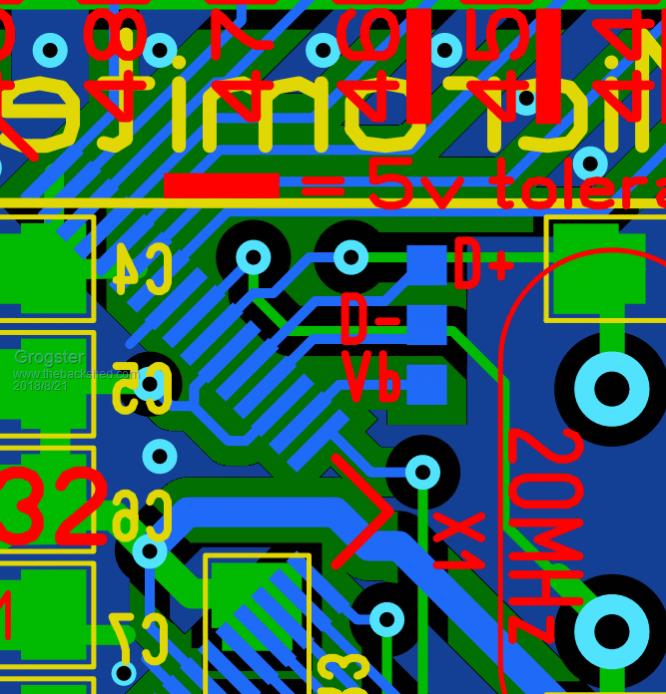 @ Rob - Not prepared to budge on the board size, sorry. Mainly, it is for MY designs that use the E64 as the main processor now. I want the 1455 features on those boards, but I am not prepared to redesign the motherboards for those systems, to accommodate a bigger E64 module. Currently, I can just swap the E64 module for a very fast upgrade of both the MMBASIC firmware(if that has been done), and the program code. Any problems? Swap the original module back in, fire it up and you are back to where you were before in seconds. Not quite hot-swappable, but pretty close. Smoke makes things work. When the smoke gets out, it stops! |
||||
| TassyJim Guru Joined: 07/08/2011 Location: AustraliaPosts: 6538 |
Half way there. I was thinking of three pairs of pads that can be bridged with a solder blob to reinstate the "old" connections. Not for me. The only time I use the USB is for testing other peoples problems. Jim VK7JH MMedit |
||||
| Page 1 of 4 |
|||||
| The Back Shed's forum code is written, and hosted, in Australia. | © JAQ Software 2026 |
