
|
|
Forum Index : Microcontroller and PC projects : Altronics Relay Board
| Author | Message | ||||
| LouisG Senior Member Joined: 19/03/2016 Location: AustraliaPosts: 130 |
Re Altronics 10A Relay Modules: Cat. Z6325, Z6327 and Z6328 (on page 213). Has anyone tried these modules using standard Micromite 3.3V inputs? (Not open collector operation). They are advertised as using 5V signals and use opto-couplers at the inputs. They look like nice units. Would appreciate feedback using 3.3V signals. Supply voltage would still be 5V. Louis |
||||
Quazee137 Guru Joined: 07/08/2016 Location: United StatesPosts: 603 |
Here is a link to a pdf KY-019 relay 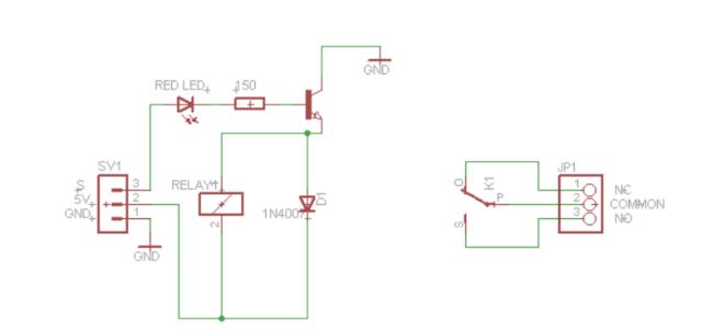 From the looks of it the Schematic has the transistor E C swapped. If you have one you could measure Vled and the VBE. You could then adjust the trip voltage down ward by removing the LED adding more resistance to keep the current safe for the driving pin. A bit later found this schematic with same part number at also KY-019 relay 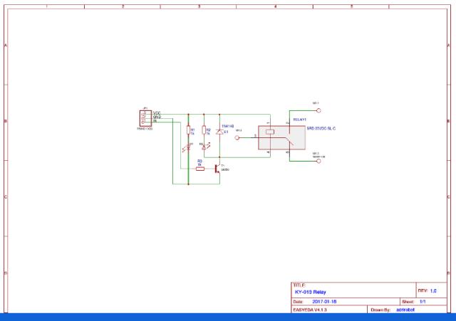 and in this schematic it looks more like you may able to use a lower voltage. I couldn't read the transistor number to look it up. I also noticed that one of do not these have a high voltage slot/gap and with 120/240 AC should be used with caution. Images of these two KY-019 relays 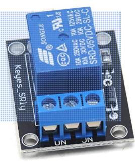 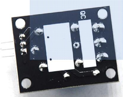 and 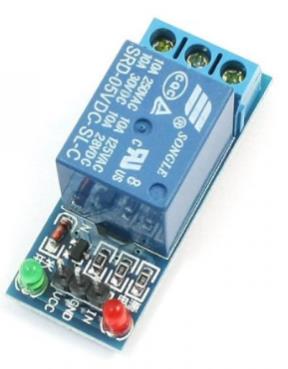 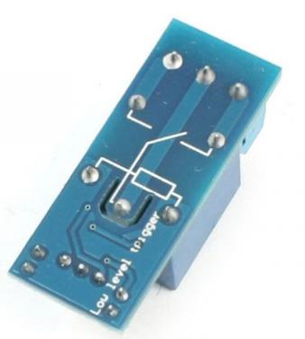 Heres hoping any of this helps. Quazee |
||||
| LouisG Senior Member Joined: 19/03/2016 Location: AustraliaPosts: 130 |
Thanks Quazee. You seem to have found a different board. The one I was referring to is at https://www.altronics.com.au/p/z6328-8-channel-5v-relay-control-board/ It definitely uses opto-couplers that give total isolation (needed). The relays will only be switching 24V DC. I might need to buy one to see if it works with 3.3V inputs. Eventually I will need 4 boards (plus one spare), each with 8 relays. Louis PS. My brother has your name as his nickname. He has had it ever since he went to a party dressed up as Quasi Modo - The Hunchback of Notre Dame. |
||||
Grogster Admin Group Joined: 31/12/2012 Location: New ZealandPosts: 9975 |
Clickable link to relay boards above... From what I can see at first glance, they are using opto-coupler inputs for all relays. This SHOULD mean that you can use with just about any input voltage, provided you perhaps adjust the opto-coupler LED's series resistor to suit. Smoke makes things work. When the smoke gets out, it stops! |
||||
palcal Guru Joined: 12/10/2011 Location: AustraliaPosts: 2039 |
Ali Express have the same board for $4.30 and a single for $0.60, if you can wait a few weeks for delivery you can have a play. "It is better to be ignorant and ask a stupid question than to be plain Stupid and not ask at all" |
||||
| PeterB Guru Joined: 05/02/2015 Location: AustraliaPosts: 669 |
G'Day Louis. Firstly I don't understand what you mean by "supply voltage would still be 5V". Can you explain that a bit more? Next, you need 50 relays! that's a lot. If you only needed 1 it might be worth a try but the chances of 50 working is probably asking a bit much. So what to do? Octal buffers would solve the problem but that would mean a new PCB and probably not what you want. As Grogster noted, you could change the resistor value and you wouldn't need to replace the existing Rs just put the appropriate value in parallel. But 50, you may go mad. But it is a fun way to go mad. Good luck. Peter |
||||
| LouisG Senior Member Joined: 19/03/2016 Location: AustraliaPosts: 130 |
Thanks guys. @ PeterB - The 5V is to power the board and for energising the relay coils. The 3.3V signals go to the individual opto inputs. Two more small comments. Galvanic isolation is needed to separate the Micromite signals (and common) from the 24V field circuits. If the relay board is powered from the same 5V as the MM is, then opto-isolation is not really needed. The relay contacts are already well isolated from the Micromite. If the board is powered from a separate 12 or 24V supply then it the optos are needed. These board makers seem to be blindly playing follow the leader. Way back, the first board maker hit on the idea of bringing out all three changeover contacts of a relay to terminals, which is a bit pointless in most cases. 1. One N.O. terminal is the switched output, that's fine. 2. This leaves the common terminals all still needing to be tediously linked together to carry the (say) +24V field supply. Couldn't this linking have been done via the printed circuit? 3. The N.C. terminal is in the vast majority of cases unused. A wasted terminal. Once upon a time N.C. contacts were useful when relay logic was in vogue. Not needed now for simple 1:1 isolation of microprocessor outputs ... 4. There is nowhere to terminate the return conductor of a field device. One has to start organising a row of terminals external to the board for the return conductors, when all the while there are unused terminals on the board that are unusable ... In contrast, the industrial PLC manufacturers seem to get the terminal arrangement right on their I/O cards. My 10c. Now I feel better. - |
||||
| Boppa Guru Joined: 08/11/2016 Location: AustraliaPosts: 816 |
Dagnabit forum ate my post I used the 5v boards on my prototyping MM with no issues (8 channel 5v from ebay), but I feed 5v into the vcc input pin, 3.3v from the MM into the switch pin and both PSU gnds tied together This seems reliable so far, I've never noticed it misfire The two madeup units I built uses 3.3v ones from aliexpress 4ch 3.3v relay pcb this is a 4 channel one as thats all I needed BTW anyone noticed that ebay.au seems to be down??? has been all morning |
||||
TassyJim Guru Joined: 07/08/2011 Location: AustraliaPosts: 6538 |
Ebay OK for me at 07:36 Some of the relay boards are 'active low', which can be annoying. Jim VK7JH MMedit |
||||
| Boppa Guru Joined: 08/11/2016 Location: AustraliaPosts: 816 |
Its back up now, isitup.com said it was down too, several people on their facebook page had issues too lol Havent had any active lows as yet, all mine have been active high to date |
||||
| PeterB Guru Joined: 05/02/2015 Location: AustraliaPosts: 669 |
G'Day All I am tickled pink that 3.3 V devices exist. I didn't know that. The next question is, is there a 3.3V stepper driver? There are at least 2 types very similar in appearance. One is labeled +5V the other just + & -. I think they both use the TB6600. I wish the world would decide on a standard and stick to it. Peter |
||||
| Boppa Guru Joined: 08/11/2016 Location: AustraliaPosts: 816 |
3v steppers ebay there you go edit sorry, I blinked over the driver bit, thats just 3v stepper motors, obviously there must be drivers as well |
||||
| Quazee137 Guru Joined: 07/08/2016 Location: United StatesPosts: 603 |
Wrong one for sure. I grabbed "Re Altronics 10A Relay Modules: Cat. Z6325" thinking it was most likely the first item you was after. I have been using the sink version of the 1, 2, 4, 6, 8 and 16 relay modules found on the net. I have to use the sink version because of pumps, valves and big motors making lots noise. I have never had a miss fired relay from the noise. A few of the controllers the MicroMites are replacing had a lot of after though protection added as they do use a high level to drive the relay portion. And when your with in a few feet of a monster 3 phase motor things do happen. With any opto-coupler with status led in line should be able to run at lower voltage by passing the led "that is if you don't need local indication of status. |
||||
| The Back Shed's forum code is written, and hosted, in Australia. | © JAQ Software 2026 |
