Notice. New forum software under development. It's going to miss a few functions and look a bit ugly for a while, but I'm working on it full time now as the old forum was too unstable. Couple days, all good. If you notice any issues, please contact me.
Warpspeed Guru Joined: 09/08/2007 Location: AustraliaPosts: 4406
Posted: 02:29am 19 Sep 2018
Copy link to clipboard
Print this post
I myself am rather "software challenged" and fully appreciate the difficulties. I have always worked with very good software people, and have concentrated my efforts on the hardware side, building a rock solid hardware foundation that the software guys can then exploit to the fullest.
If you want to do PWM, and do it with discrete components you get to choose between an analog solution or a digital solution. Both have merit, and the choice is entirely yours.
My own 5Kw sinewave inverter uses a discrete digital approach but its not PWM. The same technique could be applied to developing a PWM system.
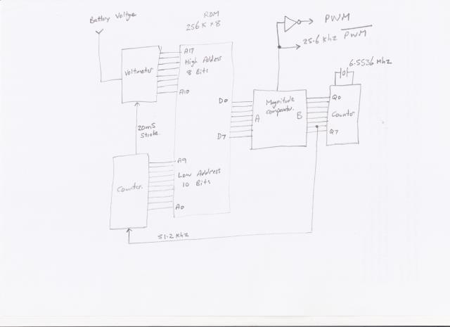
The basic idea is to have a sine lookup table in PROM and use that to generate PWM by comparing the sine data points to a continuously clocked high speed counter in a magnitude comparator. The magnitude comparator output will be direct PWM.
By using multiple lookup tables the amplitude of the PWM can be changed to effect voltage regulation by changing between lookup tables at the zero crossing points.
A further refinement is not to use voltage feedback from the inverter output, as this can introduce all kinds of stability problems if its not made slow to correct. A complicated PID system would be needed and it all becomes too hard to do digitally without a microprocessor.
A much simpler and more effective approach IMHO, is voltage feed forward correction.
We measure the incoming dc rail and from that decide which lookup table we need to generate 230v output (or whatever). Its very fast acting and can never become unstable. The no load output voltage from the inverter will obviously be slightly higher than the full load output voltage. But the voltage regulation of the grid is never perfect either. A full load drop of a very few percent is entirely acceptable.
All that is needed is an averaging digital voltmeter to select the high order address of the ROM that holds all the lookup tables, and latch the high order address into the ROM at the zero crossings.
This is the general idea for a proposed very basic eight bit PWM system. This definitely does work, although a higher bit resolution for generating the PWM would be an improvement. There are not too many parts, and its all fairly straightforward digital.
Cheers, Tony.
poida Guru Joined: 02/02/2017 Location: AustraliaPosts: 1387
Posted: 07:24am 19 Sep 2018
Copy link to clipboard
Print this post
Hey, Wiseguy, I will have a look at this, to confirm your findings. In the near future. I have just reanimated the failed inverter board, with 12 new HY4008 and a new EG002, modified to disable all over current shutdown. This is my standard setup and it runs well for the $$.
If I read your first post in this thread correctly, I need to watch the high and low side gate drives of both the 50Hz and the SPWM outputs, looking for events where both high and low gate drives are driven high at the same time. Your hints are this event occurs when over temp is sensed and when over current is sensed. Also it occurs during the restarts.
Ok, I just got home from work and that means it's approximately Beer O'clock. (the best high energy electronics seems to be engineered after I've had a few, it seems. Maybe it relaxes my anxiety of big energy failures and lets me think more better-er) wronger than a phone book full of wrong phone numbers
renewableMark Guru Joined: 09/12/2017 Location: AustraliaPosts: 1678
Posted: 07:35am 19 Sep 2018
Copy link to clipboard
Print this post
If you actually built one you would see that they are in fact very reliable. I restarted mine at least a dozen times from under voltage, no problems at all. There might be a little blip on your scope, but it obviously doesn't hurt the machine, there are many of these running perfectly fine. Recently a few problems people have have been explained for totally different reasons. So I don't understand why you have such a bee in a bonnet about it having problems restarting when they simply don't.
Anyway if you don't like the 8010 then build a 4 transformer type like Warp does, but you'll need 4 different sized transformers.Cheers Caveman Mark Off grid eastern Melb
wiseguy Guru Joined: 21/06/2018 Location: AustraliaPosts: 990
Posted: 07:50am 19 Sep 2018
Copy link to clipboard
Print this post
Hi Poida, good to hear from you and thanks for taking the challenge.
You read well what is required after an over temp or over current event but the other restart was following an over or under voltage event - this is not a real life feedback - it was setting 3V on a trimpot fed to the VFB and then pulling that level high and low. After the VFB event restart, the overlap sometimes occurred after 2 or 3 attempts at a restart
I must have been tired when I drew & presented my schematic I was probing pins 29 & 30 from the EG8010 not 27 & 28 as the schematic shows. I only probed pins 28 & 30 that appeared to be the 25kHz signal, when I noticed that overlap event - I did not probe the other 2 pins for the 50Hz so it may (or not) be there too.
I also was not looking at the output of the FET drivers I was looking at SPWM 3 & 4 directly at the EG8010 pins - if you are using an EGS002 board with the overlap transistors it should not have the overlap at the FET driver inputs or outputs.
This is relevant to EGS002 boards without overlap transistors or the Oztules/Mad implementation where those transistors are not included. If at first you dont succeed, I suggest you avoid sky diving.... Cheers Mike
renewableMark Guru Joined: 09/12/2017 Location: AustraliaPosts: 1678
Posted: 07:57am 19 Sep 2018
Copy link to clipboard
Print this post
Poida, I have that spare Ozinverter if you want to fiddle with it.Cheers Caveman Mark Off grid eastern Melb
wiseguy Guru Joined: 21/06/2018 Location: AustraliaPosts: 990
Posted: 08:06am 19 Sep 2018
Copy link to clipboard
Print this post
Mark, I dont know why this feels like such hard work. Thousands of people drive with faulty Airbags in their car that could kill them if they went off. I was one of the first to present my car for changeover as I dont want to take a chance.
Likewise with the inverter the EG8010 part appears to have a fundamental flaw. I dont argue that when running they might continue indefinitely for most builds ? But I just present information as I find it - you are not obliged to do anything about it.
I will not be taking that chance - my inverter will take full advantage of fast FET drivers and will probably be more at risk using the part as is.
I may offer to redesign the adaptor board and offer it to the forum community but only if they want it & feel they might benefit from it.
With regard to Tonys redesign - this is great information, but I feel not what the forum currently wants to hear. The existing inverters could benefit from a simple plug in upgrade if anyone was interested - I get it that existing users are essentially happy with what they have. This is early days into the investigation lets see where it ends up first. Edited by wiseguy 2018-09-20If at first you dont succeed, I suggest you avoid sky diving.... Cheers Mike
wiseguy Guru Joined: 21/06/2018 Location: AustraliaPosts: 990
Posted: 08:10am 19 Sep 2018
Copy link to clipboard
Print this post
Sorry Poida typo: I must have been tired when I drew & presented my schematic I was probing pins 29 & 30 from the EG8010 not 27 & 28 as the schematic shows. I only probed pins 29 & 30 that appeared to be the 25kHz signal, when I noticed that overlap event - I did not probe the other 2 pins for the 50Hz so it may (or not) be there too.If at first you dont succeed, I suggest you avoid sky diving.... Cheers Mike
renewableMark Guru Joined: 09/12/2017 Location: AustraliaPosts: 1678
Posted: 08:21am 19 Sep 2018
Copy link to clipboard
Print this post
Ohhh Jeeeeeeeez, once again, what bloody fundamental flaw. You may see something on your CRO but the machine doesn't care. If you actually run one you would know this.
Anyway good luck.Cheers Caveman Mark Off grid eastern Melb
Warpspeed Guru Joined: 09/08/2007 Location: AustraliaPosts: 4406
Posted: 08:48am 19 Sep 2018
Copy link to clipboard
Print this post
Definitely agree with that.
I have been doing this as a personal challenge, and now have something quite unique which has been very rewarding personally. Its way off mainstream though, and not of any real interest to the majority here.
The magnetics design has been particularly interesting as I wished to see if I could build a 4.5 Kva transformer using expensive thinner grain oriented steel E and I laminations that would beat a stacked toroidal design. I think I have achieved that with 20 watts of idling power, and its very easy to wind and assemble with a conventional plastic open transformer bobbin.
The idea will never become popular here because of the very high cost of the materials to do it. But its a very nice transformer and its very satisfying to see the theory put into practice and have a success with it.
I did fairly recently build a 1.5Kw Oz type inverter using an EGS002 board and it worked fine without any problems, just to see what you guys are on about. But its not really the direction I want to go further in.Cheers, Tony.
renewableMark Guru Joined: 09/12/2017 Location: AustraliaPosts: 1678
Posted: 09:16am 19 Sep 2018
Copy link to clipboard
Print this post
Couldn't you build one of your machines with re wound torroids? The 3kw torroids are getting a little rare but plenty of 2kw and 1.5 kw around. Cheers Caveman Mark Off grid eastern Melb
Warpspeed Guru Joined: 09/08/2007 Location: AustraliaPosts: 4406
Posted: 09:37am 19 Sep 2018
Copy link to clipboard
Print this post
Its possible I suppose, I had thought briefly about how to do it myself, but I had no suitable toroids or suitable wire here to make anything from. I decided to bite the bullet and get a mate of mine to wind the four transformers professionally.
Winding one toroid is a big job as you will know yourself. This thing needs four. Although the smaller ones are obviously smaller, they require a higher turns count, so are still a real pain in the bum to make.
Its not really practical Mark.
Cheers, Tony.
renewableMark Guru Joined: 09/12/2017 Location: AustraliaPosts: 1678
Posted: 09:59am 19 Sep 2018
Copy link to clipboard
Print this post
Winding torroids isn't any where near as much of a pain in the ass as people say it is, when you get the procedure down pat it's fairly harmless, 3-4 days after work and a double stacked 3kw x2 is done.
Can you use the reclaimed aero sharp wire? 1x 3kw and 3x 2kw cores would be enough yeah? Cheers Caveman Mark Off grid eastern Melb
renewableMark Guru Joined: 09/12/2017 Location: AustraliaPosts: 1678
Posted: 10:12am 19 Sep 2018
Copy link to clipboard
Print this post
Wiseguy, for the record Warp really dislikes the PWM inverter idea, but even he who dislikes them said it works fine. The only person here who says they don't work is someone who hasn't built one. I'll leave it at that.Cheers Caveman Mark Off grid eastern Melb
Tinker Guru Joined: 07/11/2007 Location: AustraliaPosts: 1904
Posted: 10:34am 19 Sep 2018
Copy link to clipboard
Print this post
Hear hear. From myself there is lots of kudos due to anybody who actually built a complete inverter, whether from scratch or using a pre made PCB, AND got it running satisfactory.
Quite a few here have found out that is not as easy as it seems.
But I can't recall any of these successful builders suggesting improvements here *before* having actually built a working inverter.
There is no kudos at all available from my side for suggestions that have not yet been proven in a practical application, however well these are meant or have theoretical knowledge backing. Klaus
Warpspeed Guru Joined: 09/08/2007 Location: AustraliaPosts: 4406
Posted: 10:43am 19 Sep 2018
Copy link to clipboard
Print this post
Its not that I dislike PWM, but I have been thinking about this alternative inverter idea for a great many years. I built the very first one about 35 years ago, 500 watts running off 12v. Still have it in fact.
I have built a couple more since then, all very encouraging. This latest one will be 5Kw continuous which is far more than I really need. Could have done it with PWM, but this makes for a much more interesting challenge as its quite unique in many ways.
Still very interested in what you PWM guys are doing, and will help in any way I can.Cheers, Tony.
poida Guru Joined: 02/02/2017 Location: AustraliaPosts: 1387
Posted: 10:48am 19 Sep 2018
Copy link to clipboard
Print this post
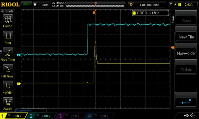
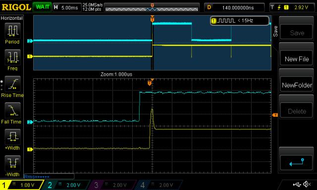
I cooked dinner, had a beer and had a look - my way. Instead of NAND gates, which I have exactly zero in the collection, I made a simple resistor adder.
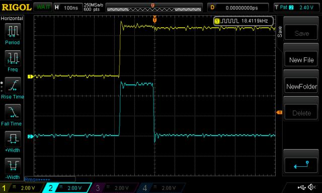
Take output of pin 29, put a 4.7K in series, pin 30 again a 4.7K in series, join these two resistors at a point and again put a 4.7K pulling that point to ground. When both pins are high, I see approx 3.75V, when one or the other pin is high the voltage is about 1.6V. It has adequate frequency response to confirm Wiseguy's observations. I needed to attach 4 wires to the emitters of Q2..Q5 to get the raw output of the EG8010.
I could not figure out how to configure a trigger on two inputs with the Rigol DS1054Z.
I saw the shoot-through gate drive after the EG8010 resumes from an over temp signal. Every time. At the start of the first 50Hz cycle. It happens on the SPWM outputs only, not the 50Hz outputs.
here are a few 50Hz cycles (at the top trace) with a zoomed in view of the shoot-through event at the bottom trace. It gives us some context of when it occurs.
I next took the outputs from the EGS002 pins 8 and 10 which are the gate drive outputs for the SPWM, added them and tried to find the shoot-through situation. It did not occur. Whether it is prevented by the dead time (IR2110) or the transitors (eg Q2 to Q5) I can't say.
So the EG8010 does in fact generate this unwanted output. The EGS002 module prevents this shoot-through gate drive signal.wronger than a phone book full of wrong phone numbers
Warpspeed Guru Joined: 09/08/2007 Location: AustraliaPosts: 4406
Posted: 11:02am 19 Sep 2018
Copy link to clipboard
Print this post
EGS002 has adjustable dead time. That may be enough to swallow that pulse if its set wide enough.Cheers, Tony.
poida Guru Joined: 02/02/2017 Location: AustraliaPosts: 1387
Posted: 11:09am 19 Sep 2018
Copy link to clipboard
Print this post
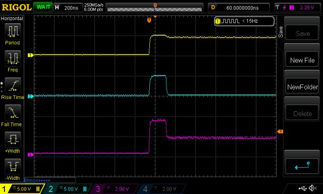
Here is a better sample of the two outputs (pins 29,30). The 4.7K R resistors I used in the adder let the capacitance of the breadboard become large enough to low pass filter the signals. With 680 R resistors things look a lot better.
Yellow is pin 30 Light Blue is pin 29 Purple is the sum of these pins via the resistive adder.
Warpspeed, I do not think the dead time adjustment has any effect on this glitchy output from the IC.
I finally got the trigger working. Here it is with good bandwidth.
Using the "duration" trigger, I could determine the width of this shoot-through. No events had shoot-through longer than about 180ns.Edited by poida 2018-09-20wronger than a phone book full of wrong phone numbers
wiseguy Guru Joined: 21/06/2018 Location: AustraliaPosts: 990
Posted: 12:52pm 19 Sep 2018
Copy link to clipboard
Print this post
Thank you Poida I am grateful for your efforts and that you have vindicated my findings. I also agree that this is not related to a deadtime setting as it has an overlap of (in my device ~ 250nSecs) ~ 200nSecs despite the 300nS deadtime setting.
I am interested in your thoughts Poida, knowing what the EG8010 does, what confidence do you place in using one now without any cross conduction protection? I have a sneaking suspicion I already know the answer but go ahead humour me.
Mark you said that building your inverter was at the edge of your technical understanding. You then tell me Tony has a functioning inverter using an EGS002. This is the crux of what we are discussing. I think it most probable he used an EGS002 board with the anti cross conduction transistors fitted. Oz and others elected not to use the anti crossover transistors.
If anyone else would like to chime in and make a comment about the desirability of shoot through be my guest. I feel like some of you just want to shoot the messenger.
Here I just googled shoot through for you. In a bridge, you should never ever close both Q1 and Q2 (or Q3 and Q4) at the same time. If you did that, you just have created a really low-resistance path between power and GND, effectively short-circuiting your power supply. This condition is called ‘shoot-through’ and is an almost guaranteed way to quickly destroy your bridge, or something else in your circuit.
and another
A serious short-circuit condition called shoot-through occurs when both the HS and LS power FETs are on at the same time. Shoot-through can happen even if we never intend to have both FETs on simultaneously. For instance, when the HS FET is commanded on and the LS FET is commanded off, logic propagation delay and the time required for charging or discharging the FETs’ gate capacitances can cause a short period when the HS FET is half on and the LS FET is half off. If so, current flows directly from VCC to GND through both FETs (shoot-through).
Mark if you understood more about components various tolerances, typ & max and min values, temperature dependence & temperature drift effects etc perhaps you might not feel as comfortable as you do. Sometimes something working fine at 25 degrees can self destruct at 50 degrees due to temperature related effects and even tolerances can all gang up on you.
If at first you dont succeed, I suggest you avoid sky diving.... Cheers Mike
Tinker Guru Joined: 07/11/2007 Location: AustraliaPosts: 1904
Posted: 01:02pm 19 Sep 2018
Copy link to clipboard
Print this post
Poida, could you try that on all 4 available dead times (300ns,500ns, 1us, 1.5us) please? I do not have the equipment but am curious. I run my inverters at the 500ns setting at the moment. There was never a problem when I tested the TFB function which I use to control the fan.Klaus