
|
|
Forum Index : Microcontroller and PC projects : VS6048 Solar CC Wifi Monitoring System
| Page 1 of 2 |
|||||
| Author | Message | ||||
| azhaque Senior Member Joined: 21/02/2017 Location: PakistanPosts: 131 |
Hi all, I am using EpSolar VS6048 PWM (pic shown below) Charge Controllers for my 12.5 KW solar array. The CC is rated max 48VDC and 60 Amps. 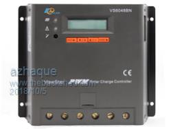 There array is divided into two parts for redundancy. The picture below shows the 24VDC 3KW inverter, with its accompanying battery bank (next picture). Two charge controllers can also be seen in the pic, that provide solar power to the inverter/battery. 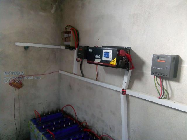 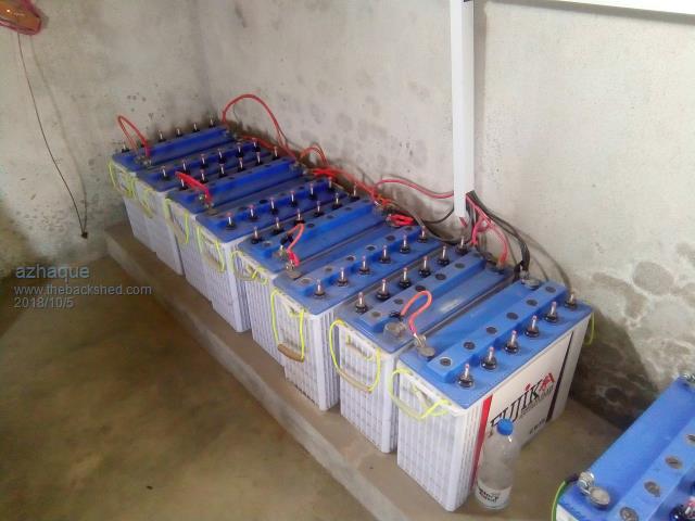 The system is mounted on a wall in the garage. It is pretty inconvenient to go to the garage, unlock the gate and then check up the system. So a need was felt to get the data wirelessly. VS6048 CCs provide a MODBUS port where data about the current, voltage and other parameters can be read. I plan to utilize this for implementing a wifi based monitoring system. I will log progress on this thread from time to time. Regards |
||||
| azhaque Senior Member Joined: 21/02/2017 Location: PakistanPosts: 131 |
I forgot to post the pics of other inverter and battery (the sun is shining on the inverter thru the garage ventilator). This is 48VDC system with the inverter rated 5KW. 7.5KWs of solar power is fed to this inverter/battery pair using 2 nos. 6048s (can be seen in the pic). This system is dedicated to run the fridge and the deep freezer and other power devices in the house. Incidentally its all off grid. 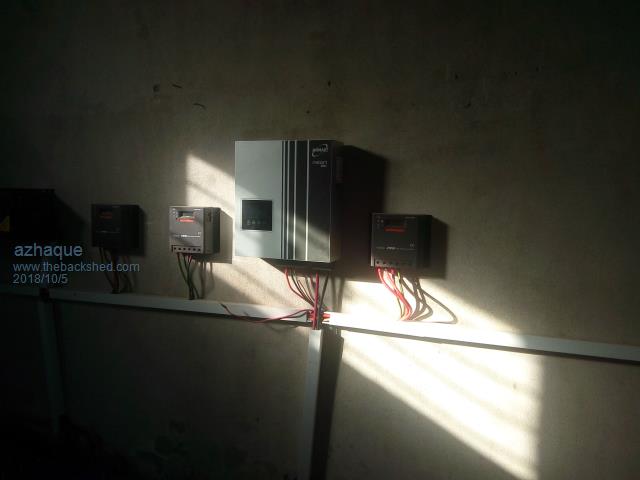 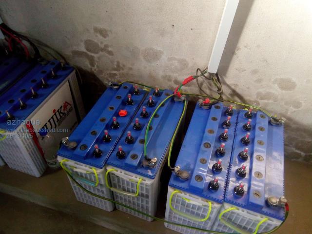 Regards |
||||
| lizby Guru Joined: 17/05/2016 Location: United StatesPosts: 3784 |
Nice-looking setup. How long have you had it running and what kind of charging input are you getting per day over what period of time? Are the lugs on the batteries so that each cell may be separately monitored? PicoMite, Armmite F4, SensorKits, MMBasic Hardware, Games, etc. on FOTS |
||||
| azhaque Senior Member Joined: 21/02/2017 Location: PakistanPosts: 131 |
Hi there Lizby, Many thanks for the kind words. The house was occupied March this year. So that makes it about 8 months. Currently I am not formally metering the energy harvested. The batteries are drained to 0% SOC when checked early morning. However by about 11:00 AM the CCs have the batteries at 100% SOC. In fact this is the rationale for this project. Initially I had only one CC per battery bank. That proved to be inadequate.So I added one more CC on each battery bank. The arrangement seems to work nicely. No. Please note that these batteries are series-parallel strings of 12 VDC, 160 AH tubular plate units. In the 24 VDC sub-system, these are strung in 2 units/series string, and 4 such strings in parallel. In the 48VDC sub-system, it is just one string of 4 series connected units. Your question about monitoring each battery separately would make a cumbersome and complex system. Whilst ideally it should be like this so that one can monitor each unit separately, however the complexity of it would be formidable. I plan to just monitor battery statistics on this wifi system including battery current, both in and out, SOC temp. etc. Hopefully with this info plus visual inspection and keeping the water topped up should keep the batteries warm and cozy. I have already fabricated an ACS758 based sensor for that purpose (pics below). Regards 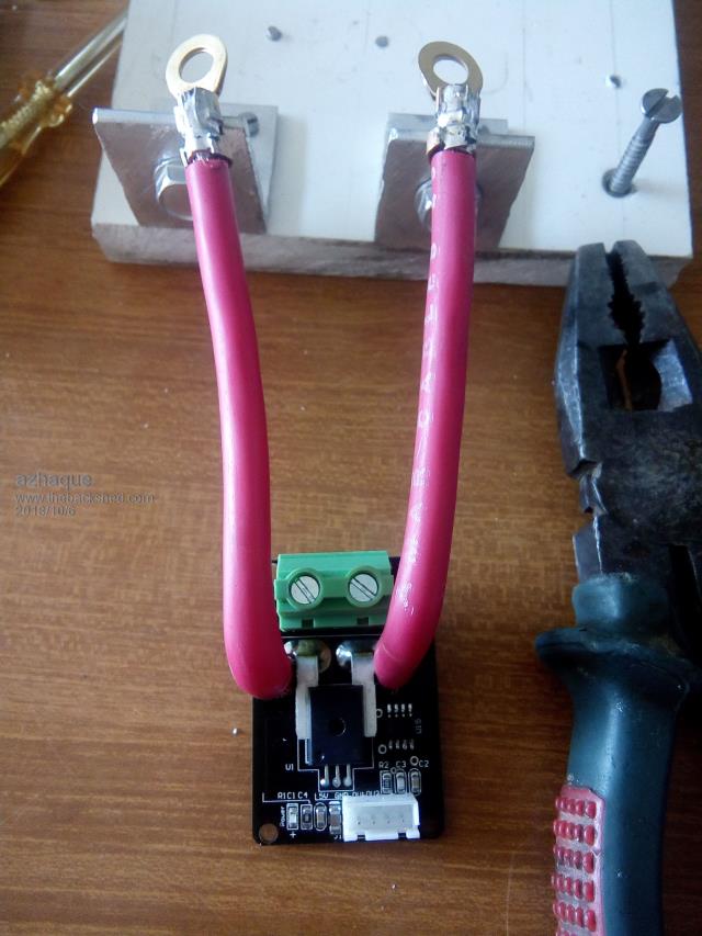 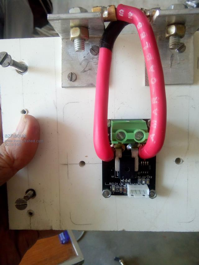 |
||||
| lizby Guru Joined: 17/05/2016 Location: United StatesPosts: 3784 |
Thanks for the additional info. Do you have plans for what to do once the batteries are at 100% SOC? By "so that each cell may be separately monitored" I was talking about what appear to be screw posts (but maybe not) next to each of the 6 openings for water on each battery. I've never seen that, and wondered what they are. They look like heavy duty batteries. PicoMite, Armmite F4, SensorKits, MMBasic Hardware, Games, etc. on FOTS |
||||
| azhaque Senior Member Joined: 21/02/2017 Location: PakistanPosts: 131 |
Hello again Lizby, I haven't the foggiest as to what to do when SOC=100%. For now these just sit and wait for the sun to go down and power the house during the night. I would certainly appreciate any pointers. These screw posts are just level-gauges for the electrolyte. I have added a pic of the same. Sure helps to avoid peeking down the water hole of the cell to ascertain whether it needs a top up. 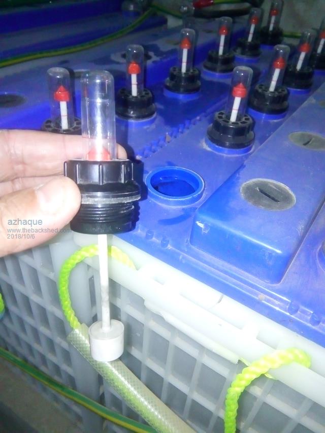 The batteries are Tall Tubular deep cycle batteries. The plate geometry is tubular instead of the usual Flat one. Locally manufactured by a company called VOLTA ( volta.com.pk ). My son has a friend who works for the company. So we get a price with a nice discount. The factory is also not very far away so cartage cost is minimal. We lugged two of these in the back of our van and brought these home. Pics with measurements attached. About twice as high as a normal 200AH car battery and about the same width. Regards and good wishes. 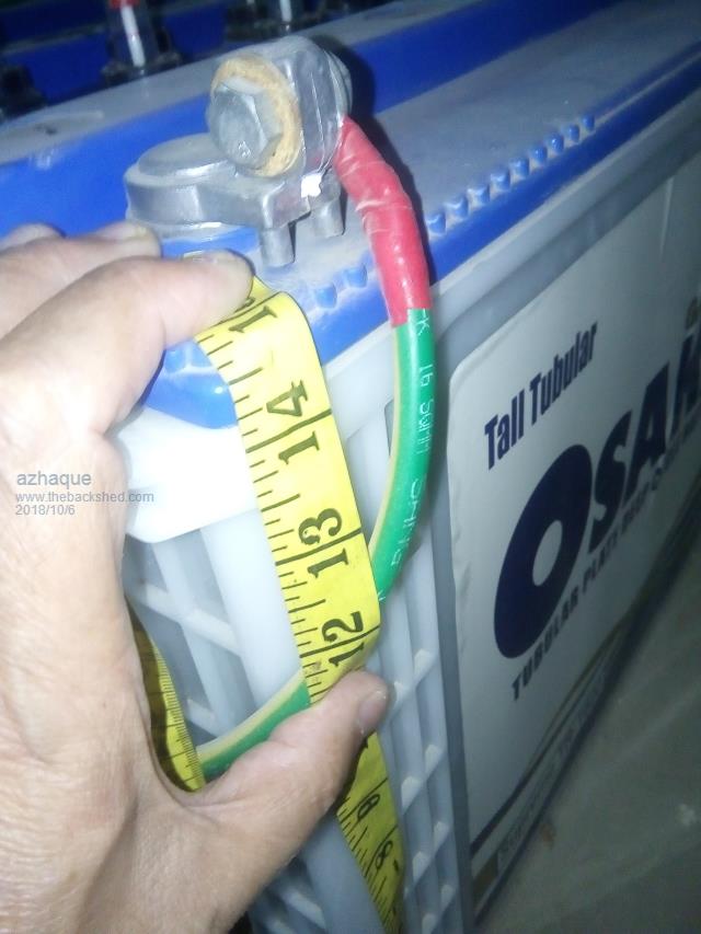 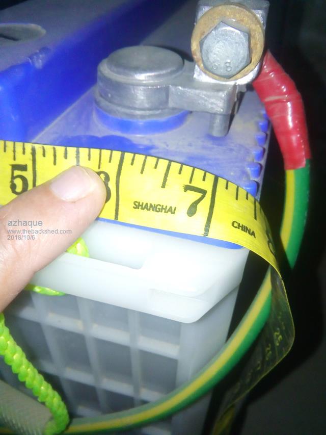 |
||||
| lizby Guru Joined: 17/05/2016 Location: United StatesPosts: 3784 |
Ok, I see--so visible electrolyte gauges--nice touch. Re pointers about what to do when SOC=100%: don't know, personally, other than more batteries. I guess some people dump to heating water (and that may be with wind, where they have +lots+ of excess after charging is done), but I don't know specifics. PicoMite, Armmite F4, SensorKits, MMBasic Hardware, Games, etc. on FOTS |
||||
| azhaque Senior Member Joined: 21/02/2017 Location: PakistanPosts: 131 |
My quest for a wifi based monitoring system started when I received my CCs. I had ordered the ones that are packaged with the e-wifi box (http://www.epsolarpv.com/en/index.php/Product/pro_content/id/731/am_id/139 ). Epsolar market the e-box packaged with its full range of CCs, both PWM and MPPT. When the e-box is connected to the CC, one can read the CC's data on a mobile phone, using a free utility provided by Epsolar. However the utility is of limited use, as there is no possibility to add or subtract parameters. So I started my search on the Net for a replacement. The first thing that turned up was a youtube video by Adam Welch (http://adamwelch.co.uk/2017/12/build-your-own-rs485-to-wifi-adapter-for-epever-solar-charge-controllers/ ). This was a designed as a replacement for the e-box wifi. However this also has limited functionality. The design was by another diyer Colin Hickey, whose youtube videos proved to be excellent guides. Further research led me to paulca's thread at eevblog (http://www.eevblog.com/forum/projects/nodemcu-esp8266-rs485-epever-solar-monitor-diy/msg1404831/#msg1404831 ) where he has implemented a system for his Tracer MPPT CC, using the Arduino environment, and NodeMCU. Since I am familiar with Arduino I decided to follow this example, with the following additionalities. 1. Add another RS485 port for the two CCs as per my system. 2. Add capability to read output from an ACS758 for battery current. You may ask that the paulca system is implemented on a Tracer series MPPT CC. Will it work on a PWM CC such as the 6048 model that I have? I believe it would. I have concluded this because EPSOLAR use their e-box wifi as well as MT50 system across all their products. So I believe that the Tracer that paulca is using and my 6048 should have similar configuration as far as the MODBUS o/p is concerned. Thanks for now. Regards azhaque |
||||
| Boppa Guru Joined: 08/11/2016 Location: AustraliaPosts: 816 |
The old exide batterys had a similar float on them (built into the watering cap) and they are indeed a huge timesaver, I had a set back in the 90's, the monthly checkup took literally seconds in most cases... walk into shed- look along floats- if all blue, do nothing, if red, top up (they even had flip open lids rather than the screwin style) These are similar, but lack the top up flip open lid water level caps |
||||
| azhaque Senior Member Joined: 21/02/2017 Location: PakistanPosts: 131 |
Hi all, First the progress this weekend. Got the veroboard populated. Got it to run BLINK  . Here is the video. . Here is the video.https://www.youtube.com/watch?v=cbtMSwUkMJs The module on the left side of the board is the power supply which provides both 5VDC and 3.3VDC. Very convenient to put onto the veroboard. Next board with the blue blinking LED is the NodeMCU with BLINK loaded and running. The small red thing in the middle is the bi-directional level shifter. Another one is yet to be installed. The connectors on the right are for the MAX485 modules. I did not have these plugged in when I made the video. -------------- To return to the design. As I submitted above I had planned to follow paulca's conceptual design, given in his post in eevblog (link provided in an earlier post). The conceptual design is given in the schematic copied below.  The variation in my design, from the above is, that there would be two streams of MAX485 instead of only one in paulca's design given above. The only issue is whether I would be able to swing two serial ports on the ESP8266. Research on the Net shows that it IS possible despite the fact that the example videos are very very rudimentary. Secondly it has to have the capability of reading the output from an ACS758 thru the on board the ESP8266's a to d converter. Wish me luck. Regards |
||||
bigmik Guru Joined: 20/06/2011 Location: AustraliaPosts: 2981 |
hi azhaque, looks great.. Err except some of your wiring looks a bit `how you do it'. I hope the HV and LV wiring is separated and not all in that ducting. Comments (critical but only on a constructive intent) Ducting is too narrow (looks like 25mm) Ducting looks like it is mounted at angles in places and too many cables inside. Some wiring on your batteries from `GND' pass through the `12V' wires at the terminal (keep these in neat runs apart from each other) The wiring to the current sensor could be cleaned up so there is no chance of shorting (not that it would cause an issue if it did) maybe mount the sense PCB 180degrees rotated. I am rather jealous of your setup but IMHO it doesn't look as good as it deserves to. Please take those comments as I intend them .. I am not CRITICISING just pointing out some simple things to make it a better project over all. Anyway we are all hobbyists keep up the good work. Kind Regards, Mick Mick's uMite Stuff can be found >>> HERE (Kindly hosted by Dontronics) <<< |
||||
Bryan1 Guru Joined: 22/02/2006 Location: AustraliaPosts: 2099 |
I run 24 volt ex forklift batteries here on the farm 600AH on the house and 735AH on the shed. The easiest way to check the SOC on a wet cell batterybank is measuring the Sg of the electrolyte. With my forklift batteries fully charged is 1024 on the guage and they don't mind going upto 1028 once a month. |
||||
| azhaque Senior Member Joined: 21/02/2017 Location: PakistanPosts: 131 |
Hello Mick, Your observations are true to the hilt. In fact I had planned to redo all the wiring when I was installing the second set of CCs. However as they say "Too many chiefs, too few braves". This quote fits me to the hilt. I gotta look after the electrical system including the backup diesel generator, manage the water system and even get the anti-rodent pellets from Islamabad which is an hour's drive from my farmhouse. This is not all. I do a public sector job that is quite demanding. In short I haven't got my act together. I read somewhere on this forum that you retired.I am also looking forward to that even in about 8 months from now. Hopefully I'll have more time to deal with the to-do list then. Kind regards azhaque |
||||
| bigmik Guru Joined: 20/06/2011 Location: AustraliaPosts: 2981 |
Hi azhaque, Yes I have been retired one week now, it still hasn't quite set in that I don't need to rise for work every morning.. the body clock still wakes me around 5:30-6:00am. Of course I realise I was talking from an Australian perspective where things are probably a lot easier to source and you, being in Pakistan, may not have all of the resources readily at hand. As well as your work load sounds like it is a miracle that you have got done what you have with all of your work load.. Anyway I am sure your day will come where retirement leaves you the time to do what you want for a change.. All good.. I was just making an observation or 5.. I have 26 x 190w panels on my roof and also grid connected.. I would one day like to add to the system and have some battery storage to go completely off grid, but I doubt I would ever get there.. Maybe a Tesla battery bank or two is not out of the question though. But while I am still getting 68c per kw I feed INTO the grid I wont consider anything like storage.. That arrangement ceases for me in 2024.. So I have a lot of reading to do on the subject between now and then. Kind Regards, Mick Mick's uMite Stuff can be found >>> HERE (Kindly hosted by Dontronics) <<< |
||||
| Paul_L Guru Joined: 03/03/2016 Location: United StatesPosts: 769 |
68c per KWH!!!! Yikes! We buy power from the local utility for 16c per KWH and they buy it from those of us who have solar panels for 4c per KWH. Our local utility (Central Hudson Power and Light) charges a relatively high price. Hydro-electric based utilities like Niagara Mohawk or Tennessee Valley sell power for as little as 3c per KWH. Paul in NY |
||||
| azhaque Senior Member Joined: 21/02/2017 Location: PakistanPosts: 131 |
Hi Paul, I think he meant Australian cents  PROGRESS I got the interconnections wired up today. I thought wiring using Dupont connectors would be easy. It turned out to be a nightmare, particularly because I don't have the crimping tool. I was using a long nosed plier to crimp. Took me half the morning to learn the trick. Then it was easier. Pic below 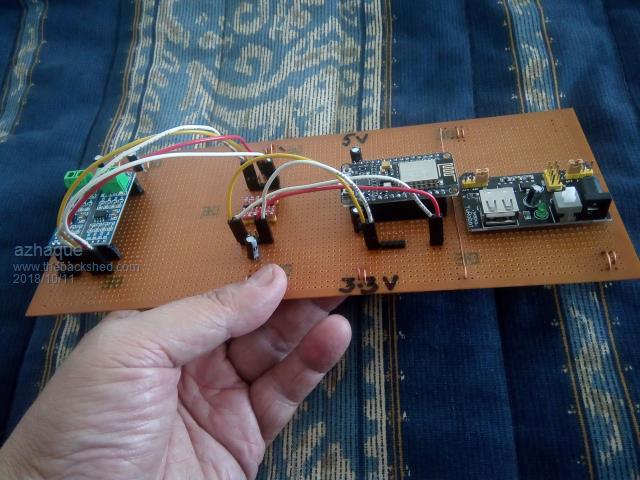 Now to locate the network wire (I know I have it lying around somewhere). Then connecting it to the CC. Yes. And I will also need to create a small Home Network on the computer. Regards all round azhaque |
||||
| Paul_L Guru Joined: 03/03/2016 Location: United StatesPosts: 769 |
$0.68 AU today equals $0.48 US. That's still ridiculously high. Paul in NY |
||||
| bigmik Guru Joined: 20/06/2011 Location: AustraliaPosts: 2981 |
GDay Paul, Whilst it does SOUND a lot consider that with my (newly renegotiated) contract I buy PEAK (7am-11pm) Electricity for about 36c inc tax and OFF PEAK at around 19c. It is NOT cheap for electricity over here compared to your messily 16c. When we bought our SOLAR in 2010 (JAN) the government was in a bind.. They couldn’t afford to buy another power plant so they thought it would be cheaper to pay a PREMIUM for Solar feed ins .. that rate (actually 66c plus my power company adds 2c) is guaranteed until 2024. Also bear in mind I paid $17500 up front for the setup.. Not cheap.. Mortgage redraw to buy it.. Today we get 8c or 11c feed in for new solar and the rates for us are the same as mine or worse depending on your supplier. But NEW setups of my size (5kw) cost as little as $4500 and the new scheme is the government will pay for half of it.. But that is in Victoria.. Other states have different pricing schemes. Once my 68c drops to the petty 8c I will NOT want to feed any back into the system I will want to store every drop so setups like the one Azhaque has will be very much what I will be looking for.. But I will most likely still need to be grid connected so maybe a couple of Tesla battery banks will be the way to go. Regards, Mick EDIT**. Retirement sucks.. I wake up at 5:30 every morning and my brain still thinks I need to leap out of bed to get ready for work... After I wake fully and realise I don’t need to do that anymore its too late to get back to sleep so I think about what the blokes are doing at work that day.. Damn I need to sand and oil the new deck today... Should have been at work.  Mik Mick's uMite Stuff can be found >>> HERE (Kindly hosted by Dontronics) <<< |
||||
| lizby Guru Joined: 17/05/2016 Location: United StatesPosts: 3784 |
You haven't yet learned how to do it. That's just WRONG! Get ahold of yourself, man. PicoMite, Armmite F4, SensorKits, MMBasic Hardware, Games, etc. on FOTS |
||||
| bigmik Guru Joined: 20/06/2011 Location: AustraliaPosts: 2981 |
@Lizby, No I haven’t yet learned how to do it properly.. There is still mucking around accessing my superannuation.. damn paperwork ... I may have to self fund for 4-6 weeks.. Anyone want to buy some PCBs?? >>> GRIN <<< just kidding.. Might have to cut down on on the WAGYU steak and go for the ANGUS Scotch fillet instead.. Ha.. No retirement doesn’t REALLY suck.. just after 33 years of a job that was more of a life style than a job it hard to punch the OFF switch.. I used to see my Missus about 4 -6 hrs a day now I see her 24 hrs a day.. That is NOT an easy adjustment... just kidding she is a wonderful woman.. Buff said Sorry to steal this thread from Azahaque. Mik Mick's uMite Stuff can be found >>> HERE (Kindly hosted by Dontronics) <<< |
||||
| Page 1 of 2 |
|||||
| The Back Shed's forum code is written, and hosted, in Australia. | © JAQ Software 2026 |
