
|
|
Forum Index : Microcontroller and PC projects : Measuring AC voltages with an MM170
| Author | Message | ||||
| Bizzie Senior Member Joined: 06/07/2014 Location: AustraliaPosts: 192 |
Hi All, We have a problem with the pressure unit supplying water to our house and gardens. I would like to log when the pump is on so I purchased a Split core current transformer here is the Datasheet . The current ratio is 30A/15mA AC (milli volts) of course. What is the easiest way to convert the above to a usable input to the MM? I am close to ignorant when it comes to the electronics to do the above. Rob White |
||||
| hitsware Guru Joined: 23/11/2012 Location: United StatesPosts: 535 |
Perhaps you can adapt this ..... |
||||
Grogster Admin Group Joined: 31/12/2012 Location: New ZealandPosts: 9975 |
Are you wanting to measure voltage or current? Or both? Those CT's (current transformers) are for measuring AC current, not for measuring voltage. How much current does your pump motor suck under load? To get even 50mV output from those CT's, you'd need an AC load of 10-amps..... Once you get down to 50mV or so, it is going to be too hard for the MM to reliably read, so you would normally connect the CT to some kind of amplifier stage before you connect it to the MCU input. Voltage is much easier. You could just use another mains transformer on the pump wiring, and with a 230v(or 110v) primary and a 3v secondary, bridge rectifier and decoupling cap(and perhaps zener snubber diode), you can feed that directly into the MM input pin. If the pin is high, the pump voltage is on, if it is low, the pump voltage is off. Can you clarify if you want to measure the voltage being switched to the pump, or the currrent sucked by the pump - or both. That will help us to help you.  Smoke makes things work. When the smoke gets out, it stops! |
||||
bigmik Guru Joined: 20/06/2011 Location: AustraliaPosts: 2981 |
GDay Bizzie, What sort of current does your Pump usually draw? It seems to me that unless it was to draw 20A or more it would produce pretty small voltages. ie. if draws only 5A it would output only 25mV.. (using the 10Ohm load as shown in the datasheet). To detect this you would need your MM close to the sensor.. as you would drop voltage across any long run. Also you need to put this clamp over only the ACTIVE (or Neutral) wire not just the entire lead (clamped over both the active/neutral) as this would counter act and read a ZERO reading as the current going down the active would put a + read and the current going the neutral would put a - read which would cancel each other. Do you just want to DETECT that the pump is running or measure the current itself? If you only wish to detect when it is powered there may be other options.. I would like to see some more details of how the pump is powered (fixed wiring or 240V mains lead) where is the detection control of how the pump knows when to turn on etc. Kind Regards, Mick Mick's uMite Stuff can be found >>> HERE (Kindly hosted by Dontronics) <<< |
||||
| bigmik Guru Joined: 20/06/2011 Location: AustraliaPosts: 2981 |
Damn Grogster, You always beat me to the punch whilst I am typing.. Remind me not to go into a boxing ring with you..  Mik Mick's uMite Stuff can be found >>> HERE (Kindly hosted by Dontronics) <<< |
||||
Chopperp Guru Joined: 03/01/2018 Location: AustraliaPosts: 1126 |
I use one of these on my grey water connected to a counter input on a Maximite. Works well. You may need a larger diameter one for a pressure pump. ChopperP |
||||
| Bizzie Senior Member Joined: 06/07/2014 Location: AustraliaPosts: 192 |
Thanks all for your quick replies! @Hitsware I am aware of that doc. @Grogster I was going to assume voltage is 240v and wanted to measure current as there are other things I was thinking I could use this for. I am aware the clamp must only go over one wire (thanks Bigmik). @Bigmik Not sure at all it is a variable speed motor (read almost constant pressure) I am guessing about 1 Hp. The pump is plugged into a power point I will go and see what my multi meter and the CT measures and report back. Thanks all Rob White |
||||
| Bizzie Senior Member Joined: 06/07/2014 Location: AustraliaPosts: 192 |
An update:- Here is my test setup 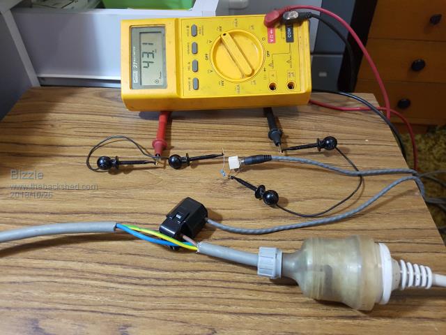 Here I have it hooked up to my oil heater the label says 2000w so that looks about right (see page two of datasheet above) at say 8amps. Now the pump reads 10.3 mV so that's about 2amps The pump label says 1.48kW (say 6amps?) max of course. Rob White |
||||
| Bizzie Senior Member Joined: 06/07/2014 Location: AustraliaPosts: 192 |
I have just watched this youtube video. Is the dangers he talks about (at about 3:30mins) of real concern? If correct these should not be sold with the exposed plug! Rob White |
||||
| Bizzie Senior Member Joined: 06/07/2014 Location: AustraliaPosts: 192 |
@ChopperP Hey that makes my mind spin a few of those around the system will tell me lots! Must see if I can locate some larger ones I think TassieJim uses 3/4" ones. Rob White |
||||
| Grogster Admin Group Joined: 31/12/2012 Location: New ZealandPosts: 9975 |
You could TRY to read that with a MM just for the purposes of experimentation, but they are TINY voltages, and would be rather prone to background noise etc. Especially if you plan to cable that tiny voltage to your MM - that probably won't work for the reasons stated by Mik. You're talking MovingMagnet record player cartridge or guitar pickup levels here. It's still do-able, but you will need some kind of amplifier for the output of the CT, before you cable to your MM. This could be as easy as an op-amp with a gain of 10 or so. I suggest you use a module such as this for three bucks. It has the CT and the op-amp voltage booster on-board for you, and an adjustable output voltage. Set it up, and job done. Even via some cable to the MM. Or there is this slightly more expensive module which can output a serial datastream to your MM's COM port, and you just read the data. Smoke makes things work. When the smoke gets out, it stops! |
||||
| Turbo46 Guru Joined: 24/12/2017 Location: AustraliaPosts: 1693 |
Bizzie, Please be aware of the dangers of open circuiting a current transformer (CT) see here under the safety heading. where I used to work we used several power diodes in series (two lots in opposite directions) connected AT THE CT TERMINALS to protect against an open circuit. The output is a constant current so you could experiment with larger current sense resistors. Bill Keep safe. Live long and prosper. |
||||
| Bizzie Senior Member Joined: 06/07/2014 Location: AustraliaPosts: 192 |
Thanks Turbo I gathered that from the YouTube video. I think I will order some of the second units Grogster linked to. That is much more like what I am used to. Thanks all who have contributed. Rob White |
||||
| Turbo46 Guru Joined: 24/12/2017 Location: AustraliaPosts: 1693 |
Bizzie, One more thing, put protection at the CT terminals (it could be two back to back 3.3v zener diodes) and the current sense resistor at the point where you will be measuring the voltage. It is a constant current output so there is no concern about voltage drop. Bill Keep safe. Live long and prosper. |
||||
| Chopperp Guru Joined: 03/01/2018 Location: AustraliaPosts: 1126 |
Yeh, he does. He set me some links to some a while ago but I couldn't work out if the 3/4" or whatever referred to the connection thread size or the actual pipe size. Might ask him one day if I get around to modifying my system ChopperP |
||||
TassyJim Guru Joined: 07/08/2011 Location: AustraliaPosts: 6538 |
My flow sensors are 3/4inch BSP thread with internal diameter about 15.8mm they are rated 1-60 L/M which is more than enough for me. If you go for bigger ones, any low flow rate is likely to be inaccurate/unreliable. Re CTs Open circuit can hurt. Some have resistors built in as a safety measure but most don't. As well as having an output too small for the micromite, AC is not easy. Doable but not easy. If all you want is an on/off indicator, amplify the CT output by enough to force it into a square wave. Then look for pulses. I have a power board that turns the slave outlets on when it senses load on the control. It makes turning on my radio a one-switch instead of three exercise (and reduces standby power wastage). I am sure that Silicon Chip did a project for one a few years ago. You would get some ideas from that circuit. Jim VK7JH MMedit |
||||
| The Back Shed's forum code is written, and hosted, in Australia. | © JAQ Software 2026 |
