
|
|
Forum Index : Microcontroller and PC projects : Driver for clock pendulum
| Author | Message | ||||
| Dabbler Newbie Joined: 04/11/2018 Location: AustraliaPosts: 9 |
Hi, I am a beginner programming the Micromite. I am having difficulty getting it to do some simple things, so I am obviously missing something very basic. I think it is probably best if I can explain what I am trying to do and how I am going about it as I may be approaching it in a less than optimal way! I am making a pendulum clock where the pendulum takes 1 second to go from one side to the other. I want to generate a pulse of a varying duration to power an electromagnet that will repel a permanent magnet on the pendulum and thus keep the pendulum going. I want the pulse to adjust so as to regulate the amplitude of the pendulum swing -- keeping it fairly constant. My approach is to use a Hall Effect Sensor centred at the middle of the swing. This turns on a shortly before the pendulum reaches the central position and turns off shortly afterwards. The duration of this pulse will be shorter when the pendulum is swinging widely and longer when the pendulum�s arc is shorter. From a programming point of view, I have set pin 16 as INTH sending to a SUB that records the time as a variable, then resets the TIMER to 0. The recorded time will measure the period of the pendulum that should stay constant. (Knowing this helps to adjust the pendulum length and hence accuracy of the clock. ) I have set pin 17 as INTL sending to a SUB that records the time (variable e) and exits. �e� should be the duration of the Hall Sensor pulse � that varies depending on the arc of the pendulum. I then will scale �e� using some constants to produce the length of the pulse to the electromagnet. I want this to update every swing. The pulse to the electromagnet needs to be timed to be just after the pendulum has gone past the bottom point of its swing. This is not something that is directly detected by the Hall Sensor. It can be calculated as half the duration of the Hall pulse plus a small constant. So the first interrupt (rising) resets the TIMER to 0, the second interrupt (dropping) records the duration of the Hall sensor pulse. The timer continues to count until the next rising interrupt that records the period and resets the TIMER to 0 � on an endless loop. Pin 18 is set as DOUT and goes to the electromagnet. The difficulty I am having, is triggering the pulse when the timer gets to the calculated point, and then pulsing for the calculated duration. I have tried using PAUSE (equation to generate correct delay) then PULSE 18, (equation to generate correct duration). I then programmed so the equations were done with the answers stored as variables that were then used � PAUSE x, PULSE 18, y, but this didn�t work either. What am I doing wrong?? |
||||
| Gizmo Admin Group Joined: 05/06/2004 Location: AustraliaPosts: 5182 |
Old Telecom time keeping clock. The contacts only close when the pendulum swings dont swing far enough. The coil above it has a tapered pole, to attract the pendulum smoothly. Also remember, you cant change the duration of a pendulum by giving it more force to swing, only by changing its length. 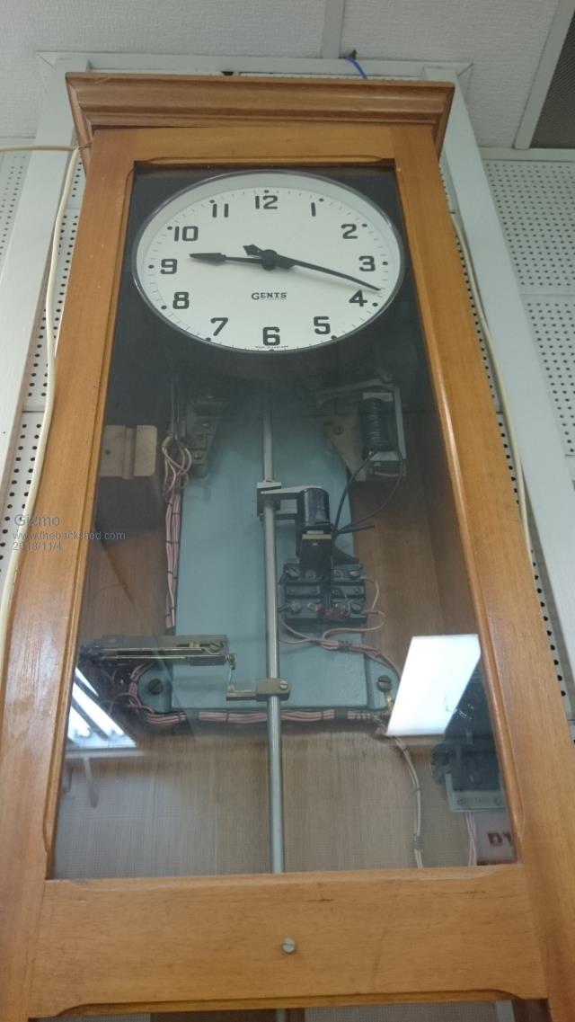 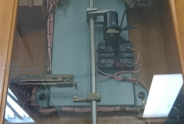 The best time to plant a tree was twenty years ago, the second best time is right now. JAQ |
||||
| circuit Guru Joined: 10/01/2016 Location: United KingdomPosts: 305 |
Edited; misread your concept |
||||
| Dabbler Newbie Joined: 04/11/2018 Location: AustraliaPosts: 9 |
To clarify, I have no intention of changing the period (time) of the pendulum swing electronically, I just want to maintain the arc (distance) of the swing. The reason is that the pendulum powers a ratchet arrangement that advances clock mechanism. For this to work well, the pendulum must swing far enough to engage the next ratchet tooth, but not too far to engage two teeth. Also, to be pedantic, the arc of the pendulum does actually affect its period to a small degree. The bigger the arc that the pendulum moves, the faster it actually goes, and a clock can be regulated to keep more accurate time by electronically varying its arc. See https://www.instructables.com/id/A-wood-gear-clock-with-a-unique-drive-mechanism/ My immediate difficulty is consistently measuring the the duration of the hall effect pulse and the pendulum period. I am using two interrupts -- on on the rising edge and the second on the falling edge of the Hall pulse. The Hall period being the time between the rising and falling edge and the pendulum period, the time between rising edges. When I set the pendulum in motion, the time the Micromite is recording fluctuate significantly, particularly the hall duration can jump to a value close to the pendulum period. I can post the code that I am using if that will help. |
||||
| Dabbler Newbie Joined: 04/11/2018 Location: AustraliaPosts: 9 |
SETPIN 16, INTH, zero 'directing to SUB zero SETPIN 17, INTL, hallDuration ' directing to SUB hallDuration SETPIN 18, DOUT:PIN 18 = 0 VAR a, e, g ' Variables; a, e = Hall Duration, f, g = Pendulum period SUB zero g = TIMER TIMER = 0 END SUB SUB hallDuration e = TIMER END SUB DO IF TIMER = (e/2) + a THEN pulse 18, f '"(e/2) + a" is calculated time to start the pulse, e/2 is the mid point of the 'Hall pulse corresponding to the exact middle of the pendulum swing. "a" is a small 'delay so the the pulse starts just after the pendulum passes the centre so the 'electromagnetic pulse will repel the pendulum giving a nudge to keep swinging. "f" 'is a value calculated from the duration "e" to give a longer or shorter pulse 'depending on how long the Hall Effect Sensor is active (formula not given here). PRINT e PRINT g LOOP I wonder if the problem is that depending on the values, the INTL can break into the pulse generation cycle and disrupt it. If so, suggestions how to get around this would be appreciated. (Or if anyone can think of a better way of achieving the same timing and pulse generation) Thanks |
||||
TassyJim Guru Joined: 07/08/2011 Location: AustraliaPosts: 6538 |
One obvious error is the use of VAR. It should be DIM Without DIM, the variables are not global which is what you want here. Jim VK7JH MMedit |
||||
| Dabbler Newbie Joined: 04/11/2018 Location: AustraliaPosts: 9 |
Thanks. The code I posted was from memory. The variables do work on the Micromite. Is the IF TIMER = x THEN "do something" the way to get an action triggered at time "x"? |
||||
| Bizzie Senior Member Joined: 06/07/2014 Location: AustraliaPosts: 192 |
Dabbler, Can you use PULSIN( pin, polarity, t1 )? Rob White |
||||
Azure Guru Joined: 09/11/2017 Location: AustraliaPosts: 446 |
A couple of thoughts (I have not done any work relating to driving a clock pendulum). Maybe let the timer free run and just take a snapshot at the start and end times, and the hall active time = end - start. Will be wrong for 1 pulse when it eventually wraps. The sensing range of hall sensors is very finicy, a lot more fussy in a pendulum setup than a fixed sensor with a fixed position rotating object. If there is any off centre travel in the pendulum (wobble/drift) it will trigger at different times or possible not at all. This could be the case for some time if the pendulum is manually taken to one side to start the movement. When a magnet pulls the pendulum it will be likely to take the pendulum slightly off its true gravitational path causing fluctuation in the hall sensor activation point. The difference between start and end may not be the exact centre of travel but slightly offset due to the activation and deactivation thresholds of the sensor. Your A offset should correct for this, but it may need to be a larger value than you think. Good luck with your project, I hope some of those thoughts may be of help to you. |
||||
| Dabbler Newbie Joined: 04/11/2018 Location: AustraliaPosts: 9 |
Thanks Bizzie. I looked at the PULSIN option but as I understand it, while this is measuring the pulse, the micromite can't do anything else, and it is during this period that the pulse needs to be generated. |
||||
| Dabbler Newbie Joined: 04/11/2018 Location: AustraliaPosts: 9 |
Thanks Guru for your thoughts. Do you think there would be any advantage of letting the timer run free? The pendulum has been set up to run smoothly and consistently. The variation in the times measured doesn't seem to relate to any change in what the pendulum is doing. There is an LED light that flashes on the Hall Sensor every time it is activated and this pulse shows no irregularity when the time recorded is wrong. There is the potential for the magnetic pulse to corrupt the perfect swing of the pendulum. From what I have read, the shorter the pulse, the less likely this is to be the case. At the end of the day, I am not expecting "atomic clock" accuracy -- I will be happy if it keeps reasonable time, while running without having to wind it up! It is important for the hall sensor to be positioned exactly at the centre of the pendulum swing. This is the main reason for recording the period of the pendulum. The position of the sensor can be fine tuned so that the time recorded for the "to" swing is the same as the "fro". I pose the question again -- Is the IF TIMER = x THEN "do something" the way to get an action triggered at time "x"? |
||||
| Bizzie Senior Member Joined: 06/07/2014 Location: AustraliaPosts: 192 |
Yep I was aware of that. Just thinking outside the square for a bit I wonder if you could measure the time on one side of the swing and do the "push" on the other? Obviously you need the Hall effect sensor exactly in the middle as you have indicated. I am also wondering if cutting a light beam may end up more precise, harder to setup though. I can not get my mind around IF TIMER = x THEN "do something" as the timer will be changing all the time so have not commented. Rob White |
||||
| Dabbler Newbie Joined: 04/11/2018 Location: AustraliaPosts: 9 |
I have considered applying the push alternate swings but my preference has been to do a little often rather than a bigger push less often. I am hoping that the Micromite will be able to power the electromagnet with its 5V logic out signal strength rather than adding in external transistor etc. I may add a capacitor to boost the pulse output. My thinking is that behind the scene, the TIMER counts 1, 2, 3, 4 . . . . and so on. At some stage it will go through the number "x". With the IF TIMER statement, my hope is that the micromite is aware of the rising count and when it reaches number "x" it will think the statement is correct so it will THEN take some action (in my case, trigger a pulse of a certain duration). All I want is a way to program it so that when the TIMER gets to a certain number, an action is triggered. |
||||
| Azure Guru Joined: 09/11/2017 Location: AustraliaPosts: 446 |
I suggested letting the timer free run since it is unlikely to ever rollover being a int. Letting it free run saves the time taken to reset it inside an interrupt and just uses simple integer maths to process the difference between the start and end travel counter values in the main loop. This is also explained in Section 5 Page 53 in the Getting Started with the Micromite pdf. Regarding use of the If statement yes that would work but more likely you will need a multiline if statement. It is probably better to use an over or under limit comparison than trying to match an exact value in this case. I think you may need to average readings and/or trigger coil based on previous timing or average as you won't know the duration or time to energise coil until after the pendulum has passed the point to energise it. Once you know the delay needed (after at least one swing) then in the hall start routine you can start a timer interrupt to do the coil acivation. This will then occur between the Hall Sensor interrupts. Edit: Not sure how long the time is between hall start and end interrupts, might be too short. I read somewhere where someone used the magnet as an inductive pickup and sensed the voltage change (+ and - swing) and used the point where it crossed zero in between to then drive it as a magnet. |
||||
| Dabbler Newbie Joined: 04/11/2018 Location: AustraliaPosts: 9 |
Thanks for your help. I will try letting the timer run free With the IF statement, do you mean something like IF TIMER > x and TIMER < (x+10) THEN PULSE 18, f I have also thought of averaging values over a number of cycles for the Hall pulse. It was simpler for me to use each reading and I didn't think it was a problem that the first few cycles would be off. It will take me a bit of thought how to do this but I recall some sample code in the Garage Parking Assistant where measurements are averaged, so this will help. I would rather not average the period time as this will stop being able to use it to adjust the position of the hall sensor to equalise the to and fro times. I have also made some physical changes to the magnet so that the hall effect sensor will be triggered earlier in the swing and turn off later. This will separate the interrupt command interfering with the pulse generation. This will have the added benefit of magnifying the difference in the pulse length from narrow swings to wide swings. The inductive pick up has been the usual way of powering pendulums. You don't even need a microprocessor in the circuit. I decided against this option for a number of reasons not least that I am even less knowledgeable about electronics than I am programming. It seems that the value of components needs to be fiddled with to get that type of system working optimally. I thought it important to leave the system as customisable as possible to fine tune the parameters. Currently, I am using a whole Micromite backpack display unit but once everything is sorted out, I hope to use a bare Micromite and if possible use the cpu sleep function during part of the cycle to maximise battery life. |
||||
Chopperp Guru Joined: 03/01/2018 Location: AustraliaPosts: 1126 |
Re pendulum length. On SBS TV tonight Michael Portillo was up the tower containing Big Ben etc. Accuracy is kept to 2 seconds a day. They use pennies to adjust the time by a fraction of a second per day. Adding a penny raises the pendulum's centre of gravity ever so slightly, effectively shortening it, making it go faster & vice versa. 2 second swing. Following on from Gizmo's telecom clocks:- Back in the early 70's when I joined DCA as it was then, we had two pendulum clocks in the Perth airport equipment room (different sort) which drove the electro-mechanical clocks throughout the operation centres (Control tower, Flight Service etc) & passenger terminals. Checked every work day morning against the PMG's talking clock or WWV on 10MHz if that was down. Again, small weights were either added or removed to adjust the time drift if necessary. At one time during a Daylight Savings trial, the clocks were either not set or reset (can't remember which) at the required time. Caused a bit of chaos until adjusted correctly. Edit. Just remembered that some of the less mature of us used to stand in front of the two units, lean forward a bit & try to sync our arms with the pendulums.  ChopperP |
||||
| The Back Shed's forum code is written, and hosted, in Australia. | © JAQ Software 2026 |
