
|
|
Forum Index : Microcontroller and PC projects : Solar charger ok for 15V mains unit?
| Page 1 of 2 |
|||||
| Author | Message | ||||
| lizby Guru Joined: 17/05/2016 Location: United StatesPosts: 3784 |
At the curiously named chinese electronics store, newfrog.com, I saw this "Solar Charge Controller" for $8.95 US: https://www.newfrog.com/product/12v-24v-lcd-auto-work-solar-charge-controller-pwm-dual-usb-output-charger-251664.01 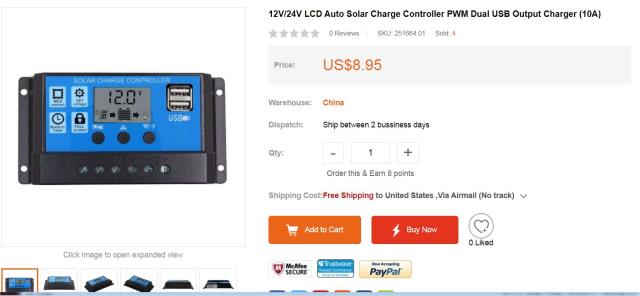 I'm interested in the solar aspect later, but right now it appears to do a lot of what I have been hoping to do to maintain a battery charge from a mains source (a 15V DC wall adapter). Of course, it says not to use anything but a solar source: "The charge regulator is only suitable for regulating solar modules. Never connect another charging source to the charge regulator." 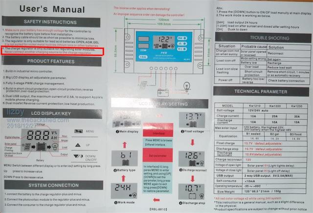 But why not? I bought 2 of them so I could tear one down to see if anything clearly could not handle a 15V wall wart. But I'm not so experienced, so I'd like other eyes to look. Tear-down is too strong a term. The case snapped open, and a pcb with components on only one side appeared. 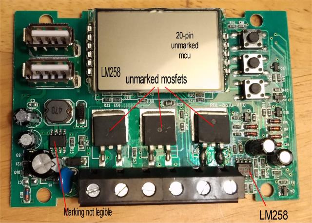 The 20-pin mcu is under the elevated LCD, with markings sanded off. There are two LM258s, 3 mosfets with markings removed, and an 8-pin IC near the caps and inductor, also unmarked. I don't see any inherent reason why I couldn't feed 15 volts where the solar is to come in and maintain my 12V 7Ah SLA battery with over-voltage and under-voltage protection for my (light) load. Of course, it doesn't have any safety markings, but neither would anything that I made. If it works, for less than $9, it's not worth my spending any more time trying to make something myself. What thoughts do shedders have? PicoMite, Armmite F4, SensorKits, MMBasic Hardware, Games, etc. on FOTS |
||||
Grogster Admin Group Joined: 31/12/2012 Location: New ZealandPosts: 9975 |
Lovely soldering on the legs of the third MOSFET on the right.....  SLA's can be trickle-charged with nothing more then a diode and resistor, which would be even cheaper then $5. It is common to find those trickle-charger arrangements in security PSU's to keep the backup batteries at full charge. The only thing they can't do, is fast-charge, so if you flatten the battery badly, it will take a long time for it to trickle-charge back up. Still, for backup things where the load on battery would not be that huge, the simple diode-gate is just about everywhere. 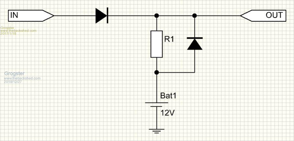 R1 sets the battery charge rate. The two diodes form the gate. The diode across the charging resistor bypasses the resistor when the main-power fails, so the battery can power the circuit. The series diode in the V+ line prevents the 12v battery voltage going back down into the OUTPUT of the mains PSU when it has lost it's power - which would not be a good thing, in general. For loads up to 1A, a couple of 1N4007 diodes(or Schottky's if you wanted a lower voltage drop), and a 33R 1W resistor - done. This is assuming at 13.8v supply. For 15v, I would just daisy-chain two series diodes in the V+ input, which will drop about 1.2v, leaving you with 13.8v on the battery, and that is spot-on perfect charge voltage for a SLA. Smoke makes things work. When the smoke gets out, it stops! |
||||
TassyJim Guru Joined: 07/08/2011 Location: AustraliaPosts: 6538 |
I will be very similar to the one I use on a solar setup. The switching is a slow PWM and is in the negative supply so be careful about tying grounds together. Solar is high internal impedance, much higher than a typical 15V supply so a big difference there. I would look at one of the adjustable supply modules that are out there. Grogster has fund some which are worth a closer look. Jim VK7JH MMedit |
||||
| lizby Guru Joined: 17/05/2016 Location: United StatesPosts: 3784 |
Thanks, grogs--I have used the diode trickle charge. What it lacks is dropout of the load when the battery gets too low. Jim--What does this mean? "so be careful about tying grounds together" And what is the practical effect of this: "Solar is high internal impedance, much higher than a typical 15V supply so a big difference there." I didn't intend to tie anything together except through the 6 connectors on the device: +/- for 12V SLA battery, solar (15VDC), and load (a 5V SMPS + raspberry pi + HC12 + SMS module, etc., for instance). PicoMite, Armmite F4, SensorKits, MMBasic Hardware, Games, etc. on FOTS |
||||
disco4now Guru Joined: 18/12/2014 Location: AustraliaPosts: 1127 |
The schematic below shows a common +ve solar controller. This has the controlling FETs in the -ve side, so you cannot join the -ve of the solar, the battery or the load together without shorting out the FETs inside the controller. If you just connect the solar to its terminals, the battery to its terminals and the load to its terminals it is good. You can't for example connect the battery -ve to the chassis and then try to also use the chassis for the return circuit for one of the loads. 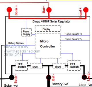 F4 H7FotSF4xGT |
||||
| JohnS Guru Joined: 18/11/2011 Location: United KingdomPosts: 4335 |
Am I correctly understanding that picture to mean the chassis is not connected to any of the terminals? Is there a best practice place to which it ought to be connected? House ground, maybe? John |
||||
| disco4now Guru Joined: 18/12/2014 Location: AustraliaPosts: 1127 |
I have cut this from a circuit I drew up for my caravan. On my van the house battery -ve is connected to the chassis. None of the loads connected to the solar controller use an earth return, all have a separate return path to the -ve load terminal. F4 H7FotSF4xGT |
||||
| TassyJim Guru Joined: 07/08/2011 Location: AustraliaPosts: 6538 |
I have 3 solar installations here. The electric fence doesn't have a regulator. IT relies on the soilar panel being correctly sized for the battery so that the maximum current when full sun and battery fully charged is within reasonable limits. The electric gate does have a regulator. The solar panel, battery and load circuits are all safely isolated on the negative rails and there is no possibility of connecting negatives. The gate uses a standard regulator similar to the one here with the low voltage cutout. I then have a 200W solar panel charging a 105AH battery. It uses a standard regulator much the same as the ones here, but I don't use the LV cutout because I need the battery negative solidly connected to ground together with the load negative. I have my own monitor for low voltage warning. Regarding the impedance of the charging circuit. The regulator is designed for a maximum current. If the supply has a very low impedance, this maximum current can be exceeded during the on time. I wouldn't trust an eBay module to have much design headroom. Jim VK7JH MMedit |
||||
| lizby Guru Joined: 17/05/2016 Location: United StatesPosts: 3784 |
What adverse consequences might be anticipated, and could they be averted with a low-resistance, high-wattage series resistor on the 15VDC supply, and if so, of what approximate values? PicoMite, Armmite F4, SensorKits, MMBasic Hardware, Games, etc. on FOTS |
||||
| TassyJim Guru Joined: 07/08/2011 Location: AustraliaPosts: 6538 |
The adverse consequence most likely is failure of the switching mosfet. I can't offer any suggestion about a series resistor. It depends on your load, impedance of the power supply, maximum current of the power supply, what mosfet is used, heatsinking (or lack of). If your load is one amp. One volt drop between 15V and 14V fully charged battery gives maximum resistance of one ohm. A one ohm resistor with a flat battery at 11 volts would give 4 amps charging plus load. At 4 amps X 4 volts we need 16 watts minimum. We are just about at Grogsters simple charging circuit. Jim VK7JH MMedit |
||||
| lizby Guru Joined: 17/05/2016 Location: United StatesPosts: 3784 |
Except for the low-voltage dropout, which was what really interested me. But thanks for supplying me the terms with which to think about it. PicoMite, Armmite F4, SensorKits, MMBasic Hardware, Games, etc. on FOTS |
||||
| HankR Senior Member Joined: 02/01/2015 Location: United StatesPosts: 209 |
The low-voltage cutout protection is available in several type of modules on ebay and no doubt elsewhere. I think you can be happy with one of these specifically designed modules (not necessarily selected from these below). I believe this will be better than improvising with a solar controller. The basic charging circuit to use with these can be the trickle charge circuit shown by G., but it doesn't have to be. Hank ____________________ module1 module 2 with mechanical switch setting of voltage disconnect and reconnect module 3 with serial port setting of many parameters |
||||
| lizby Guru Joined: 17/05/2016 Location: United StatesPosts: 3784 |
Hank--thank you for those links. They do look better suited to purpose. PicoMite, Armmite F4, SensorKits, MMBasic Hardware, Games, etc. on FOTS |
||||
| HankR Senior Member Joined: 02/01/2015 Location: United StatesPosts: 209 |
You're welcome. I think the dry contacts provided by the use of the relay are nice to have -- can come in very handy. No thinking required as to bad effects of improper grounding that can arise with solid state device switching. :) |
||||
| HankR Senior Member Joined: 02/01/2015 Location: United StatesPosts: 209 |
Just received this unit which is a dual programmed cutout with relay. Dual being switches together with LED readout, or serial port.  Under $4 US believe it or not! At that price I couldn't resist ordering and it got here quite fast. Not a stitch of instructions included, not even one of those nice 2 inch by 2 inch, one page instruction manuals. :) Fortunately fairly good instructions included in ebay listing. Have not hooked up yet. Will fairly soon. Holed up indoors. Low temp here this morning was -10 C, and this is a mild section of Massachusetts. Not too far to go to get to -14 C areas. These low temps are only noteworthy because weather has been unusually mild in Northeast US this season ... so far. |
||||
| lizby Guru Joined: 17/05/2016 Location: United StatesPosts: 3784 |
Nice find for over-voltage, under-voltage. Available on aliexpress here Rhetorical question: Why does buying 2 cost more than buying 1 twice? Look forward to seeing results of your testing. Also on ebay here PicoMite, Armmite F4, SensorKits, MMBasic Hardware, Games, etc. on FOTS |
||||
| HankR Senior Member Joined: 02/01/2015 Location: United StatesPosts: 209 |
Buying two forces an upgrade to the superior but more expensive ePacket shipping method. |
||||
| PeterB Guru Joined: 05/02/2015 Location: AustraliaPosts: 669 |
G'Day lizby Just out of curiosity I bought one of your controllers and a 30V 5A bench supply. I set up the supply for 20V and 4A and connected it all together with a 4 OHM load and a 12V battery that had been on float for days. It all behaved as expected. The power supply behaved like a solar panel and the battery charged at 4 - 3 = 1A until it reached float again. So the controller can be used as a smart battery charger BUT the device cost $10 the power supply was $63 for 5A and probably $85 for 10A so a dedicated battery charger is probably cheaper. But that is a lot of technology for $10. Peter |
||||
| HankR Senior Member Joined: 02/01/2015 Location: United StatesPosts: 209 |
Testing is taking longer than I thought. Had to locate a small blade screwdriver first. Why do those things grow legs and leave during the night? Then had to decipher/translate from the pretty bad Chinglish instructions. Now I've misplaced the very small board which I did have at first and connected to power. I can say for now that it can't do quite what I thought it could. It only has one SPDT relay, so it either operates on the charger or the load side, both not both at the same time. It's still a bargain, but too bad it doesn't have two relays. I noticed the single relay case before ordering, but 1. didn't think too much about it, and 2. it was possible that there were two relays contained in that one case, but no such luck. Just out of curiosity looked for a module that does control of both sides, but haven't found such a thing. Not too hard to design a uC based system that would do both sides, but coding the 7 segment/push button user interface to vary all the parameters would make it a non-trivial task. |
||||
| lizby Guru Joined: 17/05/2016 Location: United StatesPosts: 3784 |
PeterB and HankR--thanks for your findings. Is there any reason why an old 18V laptop power supply wouldn't work? PicoMite, Armmite F4, SensorKits, MMBasic Hardware, Games, etc. on FOTS |
||||
| Page 1 of 2 |
|||||
| The Back Shed's forum code is written, and hosted, in Australia. | © JAQ Software 2026 |
