
|
|
Forum Index : Microcontroller and PC projects : Chinese solar panel controllers
| Author | Message | ||||
| HankR Senior Member Joined: 02/01/2015 Location: United StatesPosts: 209 |
On the subject of those 3 FET topology solar controllers, I have a few I bought to evaluate and use. When they tell you to not do a certain sequence of connecting/disconnecting the solar panel, battery, and load, they aren't kidding. I released invisible smoke from one of these (non-microcontroller type) by one accidental move while rearranging a current meter to monitor the regulator action. I would like to know if anyone has analyzed the basic circuit topology of these Chinese controllers to determine: 1. What blows, and why, if the hookup sequence is violated. 2. Is it a failure mode that can be designed out without too much extra expense and circuit complexity? I can't remember for sure, but I think what I did was to momentarily break the connection to the battery while the solar panel was still connected. Immediate GONZO, brick status. Might just need one IC replaced to unbrick. Hank |
||||
| greybeard Senior Member Joined: 04/01/2010 Location: AustraliaPosts: 181 |
Narrowing down which particular model you are talking about may make it easier to provide a relevant comment/advise  |
||||
| PeterB Guru Joined: 05/02/2015 Location: AustraliaPosts: 669 |
G'Day Hank. If I understand how these things work and I may not then, The solar panel is more or less constant voltage up to a certain current and then more or less constant current. Maximum power transfer is somewhere on the knee and the purpose of the controller is to find that spot. It does this using switching techniques, which means inductance which means stored energy which means nasty back emfs if the circuit is broken. I would have thought that a diode would provide protection. I have ordered a cheap device to have a look at. Good luck. Peter |
||||
TassyJim Guru Joined: 07/08/2011 Location: AustraliaPosts: 6538 |
The cheapies don't do 'Maximum Power Point' even if they do claim to. They are simple switch-mode devices using a slow switching frequency, probably to keep the load on the mosfets down. Jim VK7JH MMedit |
||||
| PeterB Guru Joined: 05/02/2015 Location: AustraliaPosts: 669 |
G'Day Jim. I have no doubt that you are correct however my explanation of a possible failure mode is still relevant. Energy stored in an inductance has to go somewhere. Peter |
||||
| HankR Senior Member Joined: 02/01/2015 Location: United StatesPosts: 209 |
Even though the question was intentionally posed to pertain to a large class of controllers which may have much in common with respect to this vulnerability, I can show the specific unit that blew. 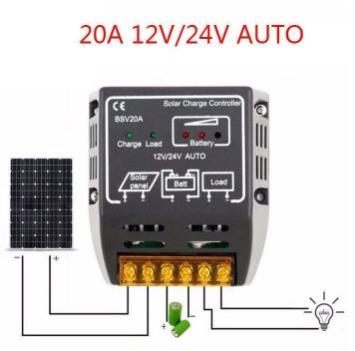 as sold on ebay This specific one is all linear (non-microcontroller) and produces varying PWM current to the battery. It does not contain any inductors as far as I can tell (there is no bucking or boosting switch mode power supply circuitry). It contains three power FETs, hence the three fet topology description I'm using. I'm guessing that the failure when disconnecting the battery might be due to the voltage rising as high as the open circuit voltage of the panel, but I would think that could easily be prevented from doing any component harm by incorporating a few simple parts (like a zener), and the Chinese designers seem often to be very clever. It would be great if there were some fairly easy and inexpensive way to prevent this kind of failure, even if it took a dollar or two extra of parts. I have other modules that are more elaborate (programmable parameter uC based), but that have the identical warning that fatal damage may occur if something is disconnected. IIRC, the something is the battery. |
||||
| Boppa Guru Joined: 08/11/2016 Location: AustraliaPosts: 816 |
Interesting- I had two of that exact same unit on the cars panels (500w total), and haven't blown them up yet, despite disconnecting/reconnecting many times (in the old exploder, I had to disconnect the battery leads to raise the back seat to access things like the snatchum strap and hand winch which I stored under the back seat in the storage compartment) the batteries sat on the rear floor behind the front seats The only difference was that the two regs outputs were tied together still when the batteries were disconnected, maybe they protected themselves that way?- personally I would expect having two to be even worse (I set it up that way as the two panels were flat mounted on the roofracks on a frame and didnt always get the same light levels, plus I started off with just the one panel and reg, but when I added the second panel, it was easier just to add the second reg than removing the original and fitting a higher capacity unit) |
||||
| PeterB Guru Joined: 05/02/2015 Location: AustraliaPosts: 669 |
G'Day All I don't like that one little bit but if it works what the hell? I have ordered one and am very eager to have a play. Peter |
||||
| HankR Senior Member Joined: 02/01/2015 Location: United StatesPosts: 209 |
Thanks for relating your (very good I'd say) experience. I should say that that was the first unit a search turned up for a buy it now unit (more likely a link that will last at least a few months), and mine is only good for either 5 amps or 10 max at most. There are a bunch of different amperage categories, but from the outside all look exactly alike. Maybe the higher amp ones are a little less delicate. It's a little surprising that you got away with simply paralleling the controllers and the batteries. Do I have that configuration right? Batteries and controllers leads brought together? Not even any isolating diodes? |
||||
| HankR Senior Member Joined: 02/01/2015 Location: United StatesPosts: 209 |
For those wishing to buy for use or experimentation one of these very cheap controllers, the one I pictured was bought maybe 4 or 5 years ago. I think there are now better ones available for less money. These are usually microcontroller based. I have one that is barely 2 inches long that has a single midget seven segment display built in (not visible until case is snapped open). Kind of amazing. That one has not been tested yet. |
||||
| Boppa Guru Joined: 08/11/2016 Location: AustraliaPosts: 816 |
Only diodes are the inbuilt ones in the panels themselves, the front panel went in through the back passengers door to its reg, then down to the passenger side 120ahr battery on the floor under the folded down back seat, then to the drivers side battery, then up to the inverter then up to the rear panel reg then out the drivers side rear door to the rear panel I know that isnt the perfect way of doing it, but it was a 'work in progress', upgraded over several years Now I have to start all over again with the new ute lol Panels aren't on it yet but used them over xmas at Fraser just leaning them against the side when camping- I am a bit worried about mounting them to the fiberglass canopy, they used to flex the steel roof of the exploder and glass doesn't flex well.... |
||||
| The Back Shed's forum code is written, and hosted, in Australia. | © JAQ Software 2026 |
