
|
|
Forum Index : Microcontroller and PC projects : Armmite L4: 5.05.04 STM32L476 support
| Page 1 of 2 |
|||||
| Author | Message | ||||
| matherp Guru Joined: 11/12/2012 Location: United KingdomPosts: 11499 |
This release includes support for the STM32L476RG as used on the NUCLEO-L476RG. The same binary is used for all supported L4 devices. 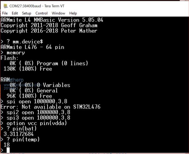 The STM32L476RG has the advantage of more RAM and more flash memory but due to a pin conflict it loses one of the three SPI ports. MM.DEVICE$ now returns "Armmite L476 - 64 pin" for the STM32L476RG and "Armmite L43x - nn pin" for the L43x series devices In addition the release supports the ST7789 display OPTION LCDPANEL ST7789, orientation, DCpin, RESETpin, CSpin and specific measurements of the chip characteristics PIN(TEMP) ' returns the die temperature of the chip PIN(VDDA) ' returns the calculated value of the analogue reference voltage PIN(BAT) ' returns the RTC battery voltage PIN(SREF) ' returns the measured internal reference voltage with a VDDA of exactly 3.0V PIN(VDDA) seems to give a higher voltage than would be expected (approximately 3.4V with an real input of 3.3V) but using it to set OPTION VCC does seem to yield more accurate analogue readings - for example to accurately read the RTC battery voltage use: OPTION VCC PIN(VDDA) PRINT PIN(BAT) 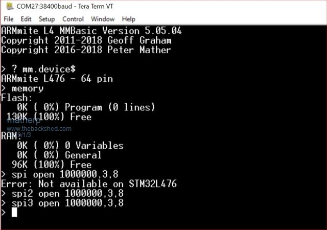 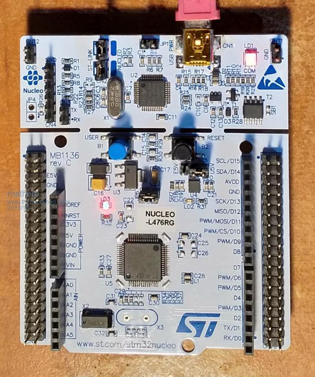 |
||||
TassyJim Guru Joined: 07/08/2011 Location: AustraliaPosts: 6538 |
Firmware link? VK7JH MMedit |
||||
| matherp Guru Joined: 11/12/2012 Location: United KingdomPosts: 11499 |
It was there honest  2019-01-03_085559_ArmmiteL4.zip |
||||
| TassyJim Guru Joined: 07/08/2011 Location: AustraliaPosts: 6538 |
Thanks. I ordered a NUCLEO-L433RC and some bare chips yesterday. It might be a while before I can find an excuse for the STM32L476RG. It will get used to pad an order out to the free freight level. Jim VK7JH MMedit |
||||
| sawasdee01 Newbie Joined: 23/12/2016 Location: United KingdomPosts: 33 |
Hi Matherp, Happy New Year and thank you for a truly wonderful addition to the MM family. Wrt to the ST7789 display driver - what are your thoughts on a capacitive touch screen driver for the many low cost 240x240 displays that have this option? Along with the low power features of the STM32L476, this would create a fantastic foundation platform for wearable projects. Best wishes. Sawasdee |
||||
| matherp Guru Joined: 11/12/2012 Location: United KingdomPosts: 11499 |
Please provide a link and I'll have a look |
||||
| sawasdee01 Newbie Joined: 23/12/2016 Location: United KingdomPosts: 33 |
Hi Matherp, Although this is a very common display, as it is used in many wearable devices, there are quite a few variations to connectors, pinouts, etc. I have tried to select three reasonably stable and well known suppliers (if there is such a thing). You may need to paste the links below directly into the address bar of Google for the searches to work correctly:- TOPFOISON A 240x240 ST7789 based display with a pre-installed capacitive touch screen. Uses the FT6206 touch screen controller. https://topfoison.en.alibaba.com/product/60851500049-807524730/Topfoioson_1_6_inch_240_240_sunlight_readable_tft_lcd_dis play_for_sport_application.html?spm=a2700.icbuShop.41413.11.70cf15c9oFuSxE AMELIN A 240x240 ST7789 based display with a pre-installed capacitive touch screen. Uses the FT6336G touch screen controller. https://amelin.en.alibaba.com/product/60830257164-807938078/1_54_inch_lcd_touch_screensmall_lcd_screen_100_new_IPS_TFT_2 40_240_with_CTP.html?spm=a2700.icbuShop.41413.17.68f97afdInuloK FORMIKE A 240x240 ST7789 based display with a pre-installed capacitive touch screen. Almost definitely uses either the FT5306 or FT5206 touch screen controller. https://www.alibaba.com/product-detail/IPS-screen-1-54-inch-tft_60786707992.html?spm=a2700.icbuShop.41413.23.65132b8cwod Kc4 All three displays have SPI interfaces, although there are also modules available with the MCU (8080?) type interface. I suspect that the Topfoison will be the highest quality product of the three and has a unit price of approx US $16 based on MOQ 1. The others can be had for approx $10 MOQ 1. Best wishes. Sawasdee |
||||
| panky Guru Joined: 02/10/2012 Location: AustraliaPosts: 1127 |
Fired up both L4's (L432KC and L476RG) with the latest code above using MBED - both worked straight out of the box. Have not tested with displays yet. panky PS. Love the NUCLEO-L476RG - quick, low power and almost as much memory as a 470, fully assembled with Arduino shield connection, all pins broken out, ST Link i/f included and CHEAP (A$23 from rs-components delivered overnight to country NSW freight free - less than assembled 170's). ... almost all of the Maximites, the MicromMites, the MM Extremes, the ArmMites, the PicoMite and loving it! |
||||
| matherp Guru Joined: 11/12/2012 Location: United KingdomPosts: 11499 |
Glad it is all working for you. The L4 code is pretty much where I want it now subject to bugs found and fixed. I have one more feature to add which is to allow the com port to wake the CPU from sleep. This would allow you to set up COM1 listening to an HC12 or similar and then go to sleep. Any incoming data could then wake the processor which could execute the incoming request and then go back to sleep - perfect for remote logging type applications. I then really need to do a manual pulling together all the goodies included in the L4 - I hate documenting  Are you using the flash file system? This, I think, is a real strong point of the L4 implementation. |
||||
| panky Guru Joined: 02/10/2012 Location: AustraliaPosts: 1127 |
Cheers Peter, I will connect up a flash ram chip tomorrow, test and let you know. Regards, Doug. ... almost all of the Maximites, the MicromMites, the MM Extremes, the ArmMites, the PicoMite and loving it! |
||||
| panky Guru Joined: 02/10/2012 Location: AustraliaPosts: 1127 |
Peter, Some problems with the L476 - I am using an Arduino shield with the Winbond 25Q32 on it wired as per your instructions. I have wired D8 on the shield as the 25Q32 chip select line. So, starting up ... > ARMmite L4 MMBasic Version 5.05.04 Copyright 2011-2018 Geoff Graham Copyright 2016-2018 Peter Mather > print mm.device$ ARMmite L476 - 64 pin > print mm.ver 5.0504 > option vcc pin(vdda) > print pin(bat) 3.302277252 > print pin(temp) 16 > ... all OK so far. Now I want to use pin D8 as the chip select for the 25Q32 so I test it first - > setpin D8,dout Error: Pin 0 is invalid > ... as pin D8 is on pin 42 of the STM > setpin 42,dout > pin(42) = 0 ... measured 0 on pin 42 / D8 > pin(42) = 1 ... measured 3.3V on pin 42 / D8 so pin 42 is D8 and works. Now I try to set up the flash > Option flash D8 Error: Pin 0 is invalid > Option flash 42 Compatible flash memory not found ... so, I have double checked the wiring to the 25Q32 and it is as follows Pin 1 : Chip select, connect to any free pin on the uP - I am using D8 Pin 2 : SPI data out, connect to SPI2-IN (D12) on the uP Pin 3 : _Write enable, connect to GND pin 4 : GND, connect to GND pin 5 : SPI data in, connect to SPI2-OUT (D11) on the uP pin 6 : SPI clock, connect to SPI2-CLK (D13) on the uP pin 7 : RESET, connect to RST on the uP pin 8 : VCC, connect to 3.3V Any suggestions as to where I am going wrong? Doug. NB. The Arduino numbering does not work on the L432 either. D. Disregard - dopey Doug - of course it does not work on the L432 - there is no Arduino connector there!!! ... almost all of the Maximites, the MicromMites, the MM Extremes, the ArmMites, the PicoMite and loving it! |
||||
| panky Guru Joined: 02/10/2012 Location: AustraliaPosts: 1127 |
Further to my last post above, a short looping program writing to SPI2 appears to have the clock on PB3 (Pin 31 of CN10/D3 on the Arduino connector) and SPI2 MOSI on PB5 ( Pin 29 of CN10/D4 on the Arduino connector). Doug. ... almost all of the Maximites, the MicromMites, the MM Extremes, the ArmMites, the PicoMite and loving it! |
||||
| matherp Guru Joined: 11/12/2012 Location: United KingdomPosts: 11499 |
The Arduino nomenclature is supported on the 432 but not (yet?) on the 476 - just use normal pin numbers. See the pinout details at the end of the first page of this thread for details. { GPIOB, GPIO_PIN_3, DIGITAL_IN | DIGITAL_OUT , NULL, 0}, // pin 55 SPI2-CLK { GPIOB, GPIO_PIN_4, DIGITAL_IN | DIGITAL_OUT , NULL, 0},// pin 56 SPI2-IN { GPIOB, GPIO_PIN_5, DIGITAL_IN | DIGITAL_OUT , NULL, 0},// pin 57 SPI2-OUT |
||||
| matherp Guru Joined: 11/12/2012 Location: United KingdomPosts: 11499 |
This minor update allows you to use the Arduino nomenclature for pins on the NUCLEO-L476RG or NUCLEO-L433RC, e.g. SETPIN A1,AIN SETPIN D2,DOUT PIN(D2)=1 PRINT PIN(A1) 2019-01-05_203903_ArmmiteL4.zip Note: the special functions assigned to the pins do not map the silkscreening on the Nucleo - see table below. Also D0 and D1 are the console pins so cannot be used for normal I/O { NULL, 0, PUNUSED , NULL, 0}, // pin 1 VBAT { GPIOC, GPIO_PIN_13, DIGITAL_IN | DIGITAL_OUT, NULL, 0}, // pin 2 { NULL, 0, PUNUSED , NULL, 0}, // pin 3 OSC32_IN { NULL, 0, PUNUSED , NULL, 0}, // pin 4 OSC32_OUT { GPIOH, GPIO_PIN_0, DIGITAL_IN | DIGITAL_OUT , NULL, 0}, // pin 5 { GPIOH, GPIO_PIN_1, DIGITAL_IN | DIGITAL_OUT , NULL, 0}, // pin 6 { NULL, 0, PUNUSED , NULL, 0}, // pin 7 NRST { GPIOC, GPIO_PIN_0, DIGITAL_IN | DIGITAL_OUT | ANALOG_IN , ADC1, ADC_CHANNEL_1}, // pin 8 -A5 { GPIOC, GPIO_PIN_1, DIGITAL_IN | DIGITAL_OUT | ANALOG_IN , ADC1, ADC_CHANNEL_2}, // pin 9 -A4 { GPIOC, GPIO_PIN_2, DIGITAL_IN | DIGITAL_OUT | ANALOG_IN , ADC1, ADC_CHANNEL_3}, // pin 10 { GPIOC, GPIO_PIN_3, DIGITAL_IN | DIGITAL_OUT | ANALOG_IN , ADC1, ADC_CHANNEL_4}, // pin 11 { NULL, 0, PUNUSED , NULL, 0}, // pin 12 VSS { NULL, 0, PUNUSED , NULL, 0}, // pin 13 VDD { GPIOA, GPIO_PIN_0, DIGITAL_IN | DIGITAL_OUT | ANALOG_IN , ADC1, ADC_CHANNEL_5}, // pin 14 COUNT/WAKEUP/IR -A0 { GPIOA, GPIO_PIN_1, DIGITAL_IN | DIGITAL_OUT | ANALOG_IN , ADC1, ADC_CHANNEL_6}, // pin 15 SPI-CLK -A1 { NULL, 0, PUNUSED , NULL, 0}, // pin 16 CONSOLE-TX -D1 // { NULL, 0, PUNUSED , NULL, 0}, // pin 17 CONSOLE-RX -D0 { NULL, 0, PUNUSED , NULL, 0}, // pin 18 VSS { NULL, 0, PUNUSED , NULL, 0}, // pin 19 VDD { GPIOA, GPIO_PIN_4, DIGITAL_IN | DIGITAL_OUT | ANALOG_IN , ADC1, ADC_CHANNEL_9}, // pin 20 DAC-1 -A2 { GPIOA, GPIO_PIN_5, DIGITAL_IN | DIGITAL_OUT | ANALOG_IN , ADC1, ADC_CHANNEL_10}, // pin 21 DAC-2 -D13 { GPIOA, GPIO_PIN_6, DIGITAL_IN | DIGITAL_OUT | ANALOG_IN , ADC1, ADC_CHANNEL_11}, // pin 22 SPI-IN -D12 { GPIOA, GPIO_PIN_7, DIGITAL_IN | DIGITAL_OUT | ANALOG_IN , ADC1, ADC_CHANNEL_12}, // pin 23 SPI-OUT -D11 { GPIOC, GPIO_PIN_4, DIGITAL_IN | DIGITAL_OUT | ANALOG_IN , ADC1, ADC_CHANNEL_13}, // pin 24 { GPIOC, GPIO_PIN_5, DIGITAL_IN | DIGITAL_OUT | ANALOG_IN , ADC1, ADC_CHANNEL_14}, // pin 25 { GPIOB, GPIO_PIN_0, DIGITAL_IN | DIGITAL_OUT | ANALOG_IN , ADC1, ADC_CHANNEL_15}, // pin 26 -A3 { GPIOB, GPIO_PIN_1, DIGITAL_IN | DIGITAL_OUT | ANALOG_IN , ADC1, ADC_CHANNEL_16}, // pin 27 COUNT { NULL, 0, PUNUSED , NULL, 0}, // pin 28 { GPIOB, GPIO_PIN_10, DIGITAL_IN | DIGITAL_OUT , NULL, 0}, // pin 29 COM2-TX -D6 { GPIOB, GPIO_PIN_11, DIGITAL_IN | DIGITAL_OUT , NULL, 0}, // pin 30 COM2-RX { NULL, 0, PUNUSED , NULL, 0}, // pin 31 VSS { NULL, 0, PUNUSED , NULL, 0}, // pin 32 VDD // { GPIOB, GPIO_PIN_12, DIGITAL_IN | DIGITAL_OUT , NULL, 0}, // pin 33 { GPIOB, GPIO_PIN_13, DIGITAL_IN | DIGITAL_OUT , NULL, 0}, // pin 34 SPI3-CLK { GPIOB, GPIO_PIN_14, DIGITAL_IN | DIGITAL_OUT , NULL, 0}, // pin 35 SPI3-IN { GPIOB, GPIO_PIN_15, DIGITAL_IN | DIGITAL_OUT , NULL, 0}, // pin 36 SPI3-OUT { GPIOC, GPIO_PIN_6, DIGITAL_IN | DIGITAL_OUT, NULL, 0}, // pin 37 { GPIOC, GPIO_PIN_7, DIGITAL_IN | DIGITAL_OUT, NULL, 0}, // pin 38 -D9 { GPIOC, GPIO_PIN_8, DIGITAL_IN | DIGITAL_OUT, NULL, 0}, // pin 39 { GPIOC, GPIO_PIN_9, DIGITAL_IN | DIGITAL_OUT, NULL, 0}, // pin 40 { GPIOA, GPIO_PIN_8, DIGITAL_IN | DIGITAL_OUT , NULL, 0}, // pin 41 PWM1A -D7 { GPIOA, GPIO_PIN_9, DIGITAL_IN | DIGITAL_OUT , NULL, 0}, // pin 42 COM1-TX / PWM1C -D8 { GPIOA, GPIO_PIN_10, DIGITAL_IN | DIGITAL_OUT , NULL, 0}, // pin 43 COM1-RX / PWM1D -D2 { GPIOA, GPIO_PIN_11, DIGITAL_IN | DIGITAL_OUT , NULL, 0}, // pin 44 PWM1B { GPIOA, GPIO_PIN_12, DIGITAL_IN | DIGITAL_OUT , NULL, 0}, // pin 45 COM1-DE /COUNT { NULL, 0, PUNUSED , NULL, 0}, // pin 46 SWDIO { NULL, 0, PUNUSED , NULL, 0}, // pin 47 VSS { NULL, 0, PUNUSED , NULL, 0}, // pin 48 VDD // { NULL, 0, PUNUSED , NULL, 0}, // pin 49 SWCLK { GPIOA, GPIO_PIN_15, DIGITAL_IN | DIGITAL_OUT , NULL, 0}, // pin 50 { GPIOC, GPIO_PIN_10, DIGITAL_IN | DIGITAL_OUT, NULL, 0}, // pin 51 { GPIOC, GPIO_PIN_11, DIGITAL_IN | DIGITAL_OUT, NULL, 0}, // pin 52 { GPIOC, GPIO_PIN_12, DIGITAL_IN | DIGITAL_OUT, NULL, 0}, // pin 53 { GPIOD, GPIO_PIN_2, DIGITAL_IN | DIGITAL_OUT , NULL, 0}, // pin 54 { GPIOB, GPIO_PIN_3, DIGITAL_IN | DIGITAL_OUT , NULL, 0}, // pin 55 SPI2-CLK -D3 { GPIOB, GPIO_PIN_4, DIGITAL_IN | DIGITAL_OUT , NULL, 0}, // pin 56 SPI2-IN -D5 { GPIOB, GPIO_PIN_5, DIGITAL_IN | DIGITAL_OUT , NULL, 0}, // pin 57 SPI2-OUT -D4 { GPIOB, GPIO_PIN_6, DIGITAL_IN | DIGITAL_OUT , NULL, 0}, // pin 58 I2C-SCL -D10 { GPIOB, GPIO_PIN_7, DIGITAL_IN | DIGITAL_OUT , NULL, 0}, // pin 59 I2C-SDA { NULL, 0, PUNUSED , NULL, 0}, // pin 60 BOOT0 { GPIOB, GPIO_PIN_8, DIGITAL_IN | DIGITAL_OUT , NULL, 0}, // pin 61 PWM2A -D15 { GPIOB, GPIO_PIN_9, DIGITAL_IN | DIGITAL_OUT , NULL, 0}, // pin 62 -D14 { NULL, 0, PUNUSED , NULL, 0}, // pin 63 VSS { NULL, 0, PUNUSED , NULL, 0}, // pin 64 VDD |
||||
| panky Guru Joined: 02/10/2012 Location: AustraliaPosts: 1127 |
Thanks Peter, File system working now on the L476 using the Winbond 25Q32 on SPI2. Arduino style pin numbering also works - thanks very much. Doug. ... almost all of the Maximites, the MicromMites, the MM Extremes, the ArmMites, the PicoMite and loving it! |
||||
djuqa Guru Joined: 23/11/2011 Location: AustraliaPosts: 447 |
Just recieved my STM32 Nucleo board Installed your wonderful version of MMBasic Worked first time You are (Plus Geoff) brilliant UPDATE:- Un-installed Armmite Firmware It works OK, but I have re-installed the Original firmware as it suits my purposes better. VK4MU MicroController Units |
||||
| panky Guru Joined: 02/10/2012 Location: AustraliaPosts: 1127 |
Peter, I am trying to hook up a SSD1306 1.3" I2C display to the L476 OPTION LCDPANEL SSD1306I2C,L,2 Your pinout doco above says I2C is on pins 58 and 59 of the L476 { GPIOB, GPIO_PIN_6, DIGITAL_IN | DIGITAL_OUT ,NULL, 0}, // pin 58 I2C-SCL -D10 { GPIOB, GPIO_PIN_7, DIGITAL_IN | DIGITAL_OUT ,NULL, 0}, // pin 59 I2C-SDA I can see the I2C clock on D10 of the Arduino connector which is pin 58 (PB6) of the L476. You show the I2C data being on pin 59 (PB7) however, this does not go out to the Arduino connector ( in fact, the circuit diagram shows it going to CN7-21 although I can not see any signal activity here). Should I2C SDA be going to pin 38 of the L476 which is PC7 (Arduino D9)? Doug. ... almost all of the Maximites, the MicromMites, the MM Extremes, the ArmMites, the PicoMite and loving it! |
||||
| matherp Guru Joined: 11/12/2012 Location: United KingdomPosts: 11499 |
The pinout is correct. I2C-SDA does not appear on the Arduino connector Just tested a BMP180 on CN10-17/CN7-21 and it works perfectly |
||||
| panky Guru Joined: 02/10/2012 Location: AustraliaPosts: 1127 |
Peter, Tested the SSD1306i2c display on an L432 on PB6/D5 as SCL and PB7/D4 as SDA with the initialisation command - OPTION LCDPANEL SSD1306I2C,L tested with TEXT 5,5,"Hello world" .. works perfectly! Tested the same display, same interconnect cables (double checked) on the L476 on PB6/CN10-17 as SCL and PB7/CN7-21 as SDA Initialised and tested as above - no go! No display! Running the same 5.05.04 on both. Any suggestions? Edit. Loaded up the latest 5.0505 - same results. ... almost all of the Maximites, the MicromMites, the MM Extremes, the ArmMites, the PicoMite and loving it! |
||||
| matherp Guru Joined: 11/12/2012 Location: United KingdomPosts: 11499 |
Thanks for the report - you found a serious bug for both 48 and 64 pins that was nothing to do with I2C but that just showed a symptom that enabled me to find it. See 5.05.05 thread for fix |
||||
| Page 1 of 2 |
|||||
| The Back Shed's forum code is written, and hosted, in Australia. | © JAQ Software 2026 |
